Note: Descriptions are shown in the official language in which they were submitted.
CA 02914380 2015-12-02
WO 2014/189997
PCT/US2014/038887
DETECTION OF SPURIOUS INFORMATION OR DEFECTS
ON PLAYING CARD BACKS
BACKGROUND OF THE INVENTION
Field of the Invention
The present invention relates to the field of playing cards, particularly
playing cards used in
wagering games, and more particularly to the security of playing cards with
respect to
spurious information and defects on the back surfaces of playing cards.
Background of the Art
Even with the highly electronic advances that have occurred within the gaming
industry,
playing cards, dice and other physical gaming objects are still important
implements within
gaming venues. Playing cards in particular are suspect of and capable of
manipulation by
players because of the intimate and repeated contact with the playing cards by
the players.
Card games and card tournaments can involve millions of dollars in individual
and total
prizes. Some players have attempted to mark playing cards on the backs or
edges of cards so
that the markings enable them to identify the suit and rank of cards without
having the faces
of the cards exposed. This provides a significant advantage to players
involved in fraudulent
marking of playing cards versus other players or the house. Even though
marking has been
going on for over a hundred years, and even though cards are visually
inspected by dealers
and automated systems can inspect or read values of playing cards, newer
techniques and
more sophisticated markings or defects can still go undetected. New types of
markings are
invisible to the naked eye, but can be clearly seen with the help of specially
made contact
lenses and glasses and small portable cameras with built in video
transmitters. Small CPUs in
pockets may be used to transfer the information to the player via wireless,
inductive
earphone. The marked cards (packaged in original boxes and sealed), chemicals
and cheating
devices are being widely sold over Internet for the last couple of years. As
recently as May
2013, an international professional poker player was accused of cheating (and
winning over
10 million dollars) in a major tournament by reading variations in printed
patterns on the
backs of playing cards. This is asserted to have occurred in spite of the
casino supplying and
CA 02914380 2015-12-02
WO 2014/189997
PCT/US2014/038887
2
controlling the cards, regular change of decks of cards, and constant dealer
examination of
the cards. Because there is a wide range of types of markings, inspections of
card backs is
usually effective for only single types of markings.
The types of markings that can be provided on backs and sides of playing cards
include at
least, visible ink, invisible inks (e.g., infrared and/or ultraviolet
reflecting ink), solvents that
smear existing inks, abrading or cutting marks, matting agents that alter
reflectivity of
surfaces, bending or curling of cards, and the like, alone or in combinations.
Manual
inspection can be done visually (with or without red color glasses that
enhance viewability of
the one part of the visible spectrum, but markings in infrared or UV can't be
detected with
the naked eye), manually (feeling for abrasions or marks) and by combinations
of these
actions.
Many different types of automated reading, sensing and optical electrical or
electromechanical systems are known for use in reading or sensing playing
cards. A non-
limiting sampling of those types of systems is reviewed below.
U.S. Patent No. 6,403,908 (Stardust) discloses an automated method and
apparatus for
sequencing and/or inspecting decks of playing. The method and apparatus
utilizes pattern
recognition technology or other image comparison technology to compare one or
more
images of a card with memory containing known 'good' images of a complete deck
of
playing cards to identify each card as it passes through the apparatus. Once
the card is
identified, it is temporarily stored in a location corresponding to or
identified according to its
position in a properly sequenced deck of playing cards. Once a full set of
cards has been
stored, the cards are released in proper sequence to a completed deck hopper.
The method
and apparatus also includes an operator interface capable of displaying a
magnified version of
potential defects or problem areas contained on a card which then may be
viewed by the
operator on a monitor or screen and either accepted or rejected via operator
input. The patent
is also capable of providing an overall wear rating for each deck of playing
cards. In order to
certify that deck of playing cards is good and acceptable for play, the casino
must ascertain
CA 02914380 2015-12-02
WO 2014/189997
PCT/US2014/038887
3
that: (1) there is one and only one of each type (i.e. by suit and rank) of
playing card in the
deck of playing cards, (2) all of the backs of the playing cards contained in
the deck are of the
same color, (3) there are no defective playing cards (i.e. torn or cracked
cards, cards with
dimples or fingernail marks, cards with missing print or cards with spots),
and (4) there are
no boxed cards (cards facing backwards, etc.) contained in the deck of playing
cards.
Imaging cameras are used to obtain one or more images of each side of the card
after the
double card check is made. A low resolution image is made of the front to
determine suit and
rank and back to determine color of the card. Generally, high resolution
imaging is utilized to
determine fine marks and problems. If the system is not in an inspect mode, it
is possible to
use the cameras simply to image a corner of the card, since the information
necessary as to
color and suit and rank is available in this portion of each card.
U.S. Patent No. 5,941,769 (Order) discloses that in professional use in table
games of chance,
playing cards are provided which will register and evaluate all phases of the
run of the game
automatically. This is achieved by a card shoe with an integrated device for
recognition of the
value of the drawn cards (optical recognition device and minoring into a CCD-
image
converter); photodiodes arranged under the table cloth to register separately
the casino light
passing through each area for placing the gaming chips and areas for placing
the playing
cards in dependence of the arrangement or movement of the chips and playing
cards on the
mentioned areas; a device for automatic recognition of each bet (scanner or a
RFID-system
comprising a SIR station and gaming objects with integrated transponder); an
EDP program
created in accordance with the gaming rules to evaluate and store all data
transmitted from
the functional devices to the computer; and a monitor to display the run of
the game and
players wins.
U.S. Patent No. 5,770,533 (Franchi) describes a casino operating system for
controlling the
flow of funds and monitoring gambling activities in a casino or a gaming
establishment
utilizing a network of computers, including a central computer and individual
game
computers. Each player receives an encoded betting card from the cashier. At
the games, each
player position is equipped with a control panel including a card reader into
which the betting
card is inserted. The control panel also includes an electronic screen and
keyboard. From the
CA 02914380 2015-12-02
WO 2014/189997
PCT/US2014/038887
4
control panel, the player may place a bet and perform all options available to
the player in the
particular game. The system records the hands dealt to each player and the
winner, and
credits or debits the player's betting card accordingly. In an alternative
embodiment, the
casino operating system allows the players to use chips to place bets instead
of the above-
described betting card. The chips are marked or encoded so that they can be
counted once
final bets have been placed to determine the amount of each player's bet. In
games requiring
the placement of bets in certain positions on the gaming table, each player
may be provided
with a betting marker used to indicate the position of his bets on the table,
a touch-sensitive
screen maybe used whereby bets are placed by touching the desired position on
the screen, or
a two-way remote control console for placing bets. The casino operating system
is an open
architecture system adaptable to accommodate the differing needs of each
casino.
U.S. Patent No. 4,531,187 (Uhland) describes a system for monitoring the play
at gambling
games. The preferred embodiment comprises a system for monitoring the play at
blackjack as
that game is played in casinos. The system typically will comprise video
monitor means for
generating a digital representation of the bets made by the players and of the
cards dealt to
the players and to the dealer, so that an output can be generated indicating
whether the correct
payouts are made and bets collected. An alarm signal is generated if an error
is made in the
play of the game. An alarm signal may also be generated if the long-term
statistics of the
game indicate that the odds ordinarily applicable to the game have been
departed from over a
period of time.
U.S. Patent No. 8,221,244 (French) describes methods and systems for
intelligent tracking
and/or play and/or management of card gaming use an intelligent card
distribution or holding
device with detectors for determining the value and unique identity of
individual cards and
for recording card play. Playing cards are equipped with a read/write data
storage connected
to a transponder and/or incorporated into electromagnetic writable particles
or smart particles
(smart dust). A system of the invention records various game play events on
the playing cards
themselves during game play and optionally also in a database on the system.
In specific
embodiments, the principal scanning and writing elements and electronic and
optical
interfaces are embodied into a hand-held card holder (HHCH). The system can
scan playing
CA 02914380 2015-12-02
WO 2014/189997
PCT/US2014/038887
cards, scan gaming chips, indicate a player's win/loss/draw, increase or
decrease player
betting positions, and compute awards to players based on their playing
activity.
U.S. Patent No. 7,967,672 (Shigeta) describes a card reading device that
comprises a rail for
5 guiding a card; card sensors for detecting a passing card which is slid
by hand and guided by
the rail, which are placed in a card sliding direction with a certain gap; and
reading sensors
for reading code attached to the card, which are placed between the two card
sensors in the
card sliding direction. The cards have the code which is printed in UV-
luminous ink on the
card, and the code comprises at least two code rows which are placed across
the card sliding
direction with a certain gap. The two reading sensors are placed in positions
which
correspond to the gap of the two code rows, and the card sensors output signal
for detecting a
position of the passing card.
U.S. Patent No. 6,629,894 (Purton) describes a card inspection device that
includes a first
loading area adapted to receive one or more decks of playing cards. A drive
roller is located
adjacent the loading area and positioned to impinge on a card if a card were
present in the
loading area. The loading area has an exit through which cards are urged, one
at a time, by a
feed roller. A transport path extends from the loading area exit to a card
accumulation area.
The transport path is further defined by two pairs of transport rollers, one
roller of each pair
above the transport path and one roller of each pair below the transport path.
A camera is
located between the two pairs of transport rollers, and a processor governs
the operation of a
digital camera and the rollers. A printer produces a record of the device's
operation based on
an output of the processor, and a portion of the transport path is illuminated
by one or more
blue LEDs. Preferably a low temperature source of light is located so as to
illuminate the area
of the card that is being scanned.
The computer or signal processor compiles the scan data and reports and
records the result of
the scans of all of the cards in the one or more decks. FIG. 15 of Purton
illustrates how a card
transport path 400 may be subdivided by locating baffles above or below the
roller pairs in
order to create distinct zones. Each zone may have a particular form of
detector, polarimeter,
diode or line scanner as well as a particular light source or lighting method.
By locating
CA 02914380 2015-12-02
WO 2014/189997
PCT/US2014/038887
6
sensors both above and below the transport path, both sides of the card may be
examined
simultaneously. This provides the opportunity to detect suit and value of an
inverted card as
well as increasing the sophistication with which tampering may be detected.
Polarized light
may be used to detect certain forms of tampering. In such a case, the polarity
of the light
source may be rotated during the detection process. Similarly, a non-polarized
source may be
moved during the detection process to create a moving shadow. One or more
light sources
may be movable or set to illuminate off-axis so that certain forms of
scratches and pinholes
may be more easily detected by their shadow or reflectance. It is contemplated
that both color
and monochrome imaging methods may provide useful information about the
condition of the
cards. Similarly both digital and analogue sensing methods are seen to have
independent
utility and functionality with regard to both suit and value detection as well
as the detection
of faults, wear and tampering. It should be noted that the
compartmentalization of the card
transport path into distinct lighting and sensing zones may be applied to any
embodiment
disclosed.
Published U.S. Patent Application Document No. 20050242500 (Downs III)
describes a
sensing system for determining the rank and suit of playing cards. The system
includes a
sensing module capable of reading a line of data from a printed image, a
position sensor and a
hardware component that combines the signals from the sensing module and
position sensor,
converts the signal to binary values and compares the converted signal to
stored signals. The
comparisons are correlated to identify card rank and Suit. The system can be
used in a
playing card delivery shoe used to control the game of baccarat. The shoe may
be a
customary dealing shoe equipped with a sensing module, or may be a mechanized
shoe. The
mechanized shoe may comprise a) an area for receiving a first set of playing
cards useful in
the play of the casino table card game of baccarat; b) first card mover that
moves playing
cards from the first set to a playing card staging area wherein at least one
playing card is
staged in an order by which playing cards are removed from the first set of
and moved to the
playing card staging area; c) second playing card mover that moves playing
cards from the
playing card staging area to a delivery area wherein playing cards removed
from the staging
area to the delivery shoe are moved in the same order by which playing cards
were removed
from the first set of playing cards and moved to the playing card staging
area; and d) playing
card reading sensors that read at least one playing card value of each playing
card separately
CA 02914380 2015-12-02
WO 2014/189997
PCT/US2014/038887
7
after each playing card has been removed from the area for receiving the first
set of playing
cards and before removal from the playing card delivery area One exemplary
sensing system
is a CIS line scanning system with an associated card position sensor and a
FPGA hardware
element.
Published U.S. Patent Application Document No. 20070018389 (Downs III)
describes a
method and an apparatus determines at least one of rank or suit of a playing
card. The
apparatus has at least one two-dimensional complementary metal oxide
semiconductor
imaging system that provides a signal when playing cards are moved over the
system. The
signal is a series of gray scale values that are converted into binary values.
The sensed data is
transmitted to a hardware component that identifies at least one of rank and
suit to an external
data storage device.
Published U.S. Patent Application Document No. 20070102879 (Stasson) describes
a playing
card shuffling device has a visual display in information communication with
the playing
card shuffling device. At least one processor is programmed to provide
displayable
information to the visual display indicative of an amount of time remaining or
time expired in
a procedure performed by the shuffling device. FIG. 1 shows a partial
perspective view of
the top surface of a first shuffling and card verification apparatus according
to a practice of
the invention. In this example of the invention, the device randomizes and/or
verifies one or
two decks of cards. The shuffling apparatus has a card accepting/receiving
area that is
preferably provided with a stationary lower support surface that slopes
downwardly from the
nearest outer side of the shuffling and verifying apparatus. A depression is
provided in that
nearest outer side to facilitate an operator's ability to place or remove
cards into the card
accepting/receiving area. The top surface of the shuffling and verifying
apparatus is provided
with a visual display (e.g., LED, liquid crystal, micro monitor, semiconductor
display, multi-
segment display, etc.), and a series of buttons, touch pads, lights and/or
displays. These
elements on the top surface of the shuffling and verifying device may act to
indicate power
availability (on/off), shuffler state (jam, active shuffling, completed
shuffling cycle,
insufficient numbers of cards, missing cards, sufficient numbers of cards,
complete deck(s),
damaged or marked cards, entry functions for the dealer to identify the number
of players, the
CA 02914380 2015-12-02
WO 2014/189997
PCT/US2014/038887
8
number of cards per hand, access to fixed programming for various games, the
number of
decks being shuffled, card calibration information, mode of operation (i.e.
shuffling,
verifying or both shuffling and verifying) and the like), or other information
useful to the
operator or casino. Among the non-limiting examples of these techniques are 1)
a sensor so
that when a pre-selected portion of the card (e.g., leading edge, trailing
edge, and mark or
feature on the card) passes a reading device, such as an optical reader, the
bottom pick-off
roller is directed to disengage, revolve freely, or withdraw from the bottom
of the set of
cards; 2) the first set of nip rollers or off-set rollers may have a surface
speed that is greater
than the surface speed of the bottom pick-off roller, so that engagement of a
card applies
tension against the bottom pick-off roller and the roller disengages with free
rolling gearing,
so that no forward moving forces are applied to the first card or any other
card exposed upon
movement of the first card; 3) a timing sequence so that, upon movement of the
bottom pick-
off roller for a defined period of time or for a defined amount of rotation
(which correlates
into a defined distance of movement of the first card), the bottom pick-off
roller disengages,
withdraws, or otherwise stops applying forces against the first card and
thereby avoids
applying forces against any other cards exposed by movement of the first card
from the card
accepting/receiving area 106 and 4) providing a stepped surface (not shown)
between pick-
off roller and off-set rollers 146 that contacts a leading edge of each card
and will cause a
card to be held up or retained in the event that more than one card feeds at a
time.
Shuffler systems, especially those having a scanning system, can be converted
to card
inspections systems or may have card inspection systems according to the
present technology
integrated into the shufflers, randomizers and playing card delivery systems.
Examples of
such card moving systems include, but are not limited to U.S. Patent Nos.
8,210,536;
8,210,535; 8,205,884; 8,191,894; 8,170,323; 8,150,875; 8,118,305; 8,109,514;
8,070,574; RE
42,944; 8,038,521; 8,025,294; 8,012,029; 8,011,661; 8,002,638; 7,988,152;
7,976,023;
7,971,881; 7,967,294; 7,950,663; 7,946,586; 7,933,448; 7,933,444; 7,854,430;
7,784,790;
7,769,232; 7,764,836; 7,753,373; 7,717,427; 7,699,694; 7,677,566; 7,677,565;
7,669,852;
7,597,623; 7,594,660; 7,593,544; 7,584,963; 7,584,962; 7,434,805; 7,413,191;
7,407,438;
7,384,044; 7,374.170; 7,367,884; 7,367,561; 7,338,044; 6,676,127; 6,659,461;
6,655,684;
6,651,982; 6,651,981; 6,588,750; and 6,588,750.
Other disclosures have also contemplated optically reading of playing cards.
For example,
U.S. Patent Nos. 6,582,301; 6,039,650; and 5,722,893 to Hill et al. describes
a shoe with a
CA 02914380 2015-12-02
WO 2014/189997
PCT/US2014/038887
9
card scanner, which optically scans a playing card as the card moves out of
shoe. The card
suit and value is then recognized by a neural-network algorithm. Other
disclosures have also
attempted to track cards by use of card shoes that optically recognize the
cards as they are
drawn from the shoe. For example, U.S. Patent Nos. 5,941,769 and 6,460,848
disclose a card
shoe with an optical device that deflects and transmits a reflected image of
the card value
imprint from the drawn playing card to a CCD image converter. Still other
disclosures have
attempted to combine detection of playing cards optically and gambling chips
by some
means. For example, U.S. Patent Nos. 5,605,334; 6,093,103 and 6,117,012 to
McCrea et al.,
disclose a game table system for monitoring each hand in a progressive live
card game. The
system comprises a shoe that optically detects the value and suit of each
card, a game bet
sensor to detect the presence or absence of a bet, a card sensor located at
each player position
to detect the presence or absence of a playing card, and a game control. The
game control
receives information on the presence or absence of a bet or playing card to
ensure a bet is
placed before the playing card is dealt.
Published U.S. Patent Application Document No. 20100019449 (Downs III)
describes how a
playing card delivery shoe is used in the play of the casino table card game
of baccarat or
blackjack or any game where cards are pulled one at a time from the shoe. The
apparatus
comprises a reader or an imager that scans lines bisecting the image at spaced
intervals. The
scanning occurs on playing cards in at least the region where suit and rank
symbols are
provided. The scanner output is a series of voltages that are converted to
binary information.
This binary information is compared to stored binary information to determine
rank and suit.
The upper surface of the output end of the shoe contains a partial barrier for
cards being
scanned. The partial barrier has an elevated surface and limits a size of a
pathway so that only
one card can be removed at a time.
U.S. Patent No. 6,460,848 (Soltys) describes a system that automatically
monitors playing
and wagering of a game, including the gaming habits of players and the
performance of
employees. A card deck reader automatically reads a symbol from each card in a
deck of
cards before a first one of the cards is removed. The symbol identifies a
respective rank and
suit of the card. There are numerous other related patents including U.S. Pat.
Nos. 6,712,696;
6,688,979; 6,685,568; 6,663,490; 6,652,379; 6,638,161; 6,595,857; 6,579,181;
6,579,180;
6,533,662; 6,533,276; 6,530,837; 6,530,836; 6,527,271; 6,520,857; 6,517,436;
and
6,517,435.
CA 02914380 2015-12-02
WO 2014/189997
PCT/US2014/038887
U.S. Patent No. 8,119,975 (Downs III) describes a high speed deterministic,
non-contact, 3-
axis free trajectory measurement device and free trajectory imaging device. A
data providing
device associated with a trajectory sensing system has at least a frame. The
frame supports at
least two sensing receivers and at least one emitter for the sensing
receivers. The sensors
5 sense movement and/or position with respect to a surface. The frame
supports a third sensor
that senses information (e.g., image data) from the surface at least in
addition to movement.
There is also a communication link from the two sensing receivers to a data
storage device; a
communication link from the third sensor to a data storage device or to a
processor and then a
data storage device; and a processor that determines position of the system
with respect to the
10 surface based at least in part on data from the two sensing receivers.
The emitters and sensors
may be carried on a hand-held device in communication with a recorder or
processor.
Other systems known to be available for reading of card symbols (e.g., suits
and rank)
include at least WIPO Published Application WO/2000/051076 (Dolphin);
Published U.S.
Patent Application Documents No. 2011020175; 2010061342; 20040026636; and U.S.
Patent
Nos. 6,726,205; 6,527,191; 6,533,276 and 8,020,869. All of the references
cited herein are
incorporated by reference in their entirety to provide enabling background for
systems and
technology and methods.
SUMMARY OF THE INVENTION
The present invention relates to the field of methods and systems for
detection of spurious or
fraudulent markings or flaws on the backs of playing cards. The invention
includes a method
and system for detecting errors on the backs of playing cards. The method
includes:
providing ambient infrared radiation at a gaming table and reflecting at least
some of that
infrared radiation off a back surface of a playing card; capturing reflected
infrared radiation
with an infrared radiation sensor; the infrared radiation sensor transmitting
signals based on
the reflected infrared radiation captured by the infrared radiation sensor;
the transmitted
signals providing data that contains image data of the back of the playing
card; and
displaying an image of the back of the playing card based on the image data.
The transmitted
signals provide data that contains image data of the back of the playing card
and is also
received by a processor that compares that transmitted data with reference
data of a standard
playing card back. Deviations from the reference data are recognized by the
processor and
identification of a card with such deviations is made. The detection system
may be an
CA 02914380 2015-12-02
WO 2014/189997
PCT/US2014/038887
11
installed casino system (with eye-in-the-sky technology), a portable box, a
hand-held device,
or a component within a shuffling device or dealer shoe.
BRIEF DESCRIPTION OF THE FIGURES
Figure 1 shows a full frontal view of a device according to the present
technology.
Figure 2 is a flow chart for a method according to the present technology.
Figure 3 is a flow chart for an alternative method for practice of the present
technology.
Figure 4 shows a perspective view of an alternative device 400 according to
the present
technology.
DETAILED DESCRIPTION OF THE INVENTION
The present invention relates to the field of methods and systems for
detection of markings
(especially spurious or fraudulent markings) or flaws on the backs or edges of
playing cards.
The invention includes a method for detecting errors in the back of playing
cards. The
method includes: providing ambient infrared radiation at a gaming table and
reflecting at
least some of that infrared radiation off a back surface of a playing card;
capturing reflected
infrared radiation with an infrared radiation sensor; the infrared radiation
sensor transmitting
signals based on the reflected infrared radiation captured by the infrared
radiation sensor; the
transmitted signals providing data that contains image data of the back of the
playing card;
and a processor evaluating an image of the back of the playing card based on
the image data
in comparison to stored or available image data of an acceptable plying card
back and/or
edge, or displaying an image of the back of the playing card based on the
image data for
visual inspection. The transmitted signals provide data that contains image
data of the back
of the playing card may also also be received by a processor that compares
that transmitted
data with reference data of a standard playing card back with respect to the
set of playing
cards in use during a casino table playing card game. The differences between
the image of
the back of the playing card based on the image data and the reference data
are either a)
highlighted in a visual display or b) the processor identifying a degree of
difference (or cards
with a degree of difference) between the image of the back of the playing card
based on the
image data and the reference data. The degree of differences between the image
of the back
of the playing card based on the image data and the reference data is
preferably identified by
CA 02914380 2015-12-02
WO 2014/189997
PCT/US2014/038887
12
the processor in b) by an alphanumeric rating, color rating or symbolic
rating. An
unacceptable or questionable degree of difference may be used by the processor
to alert
personnel, send an alert signal, or even stop game progression while the card
with the degree
of difference is further inspected. The sensor may be located at a position
elevated above a
surface of the gaming table, or even in a hand-held device swept over card
backs that might
be under suspicion. For example, the sensor may be elevated to a height
wherein infrared
radiation reflected from the back surface of the playing card at an angle of
between 60 and 90
degrees from horizontal is received by the sensor. This can be done within a
housing or on a
casino floor where the sensor is housed within a dome secured to a ceiling or
supported on a
post adjacent the table.
In a preferred method and system, in addition to the infrared radiation, the
method
contemporaneously (in an adjacent time frame, an overlapping time frame or the
same time
frame) provides ambient ultraviolet radiation at the gaming table, in a hand-
held device (see
Downs III U.S. Patent No. 8,119,975 which could be modified for practice in
the present
technology) or in a housing and reflecting at least some of that ultraviolet
radiation off the
back surface of the playing card; capturing reflected ultraviolet radiation
with an ultraviolet
radiation sensor; the ultraviolet radiation sensor transmitting signals based
on the reflected
ultraviolet radiation captured by the ultraviolet radiation sensor; the
transmitted signals based
on the ultraviolet radiation providing data that contains image data of the
back of the playing
card; and a processor comparing the transmitted data to reference data of
acceptable playing
card backs and/or the system displaying an image of the back of the playing
card based on the
ultraviolet image data for visual inspection. A processor may combine the
infrared and
ultraviolet image data to form a single composite image of the back of the
playing card. The
provided ambient infrared radiation may be pulsed at the back of the playing
card to reduce
infrared heating of the back of the playing card.
The invention may also include a system for detecting errors in the back of
playing cards
comprising:
an ambient infrared radiation source for directing infrared radiation at a
surface;
an infrared radiation sensor for capturing reflected ambient infrared
radiation;
CA 02914380 2015-12-02
WO 2014/189997
PCT/US2014/038887
13
the infrared radiation sensor configured to transmit signals based on captured
reflected
infrared radiation;
the transmitted signals providing data that contains image data reflected off
of the surface;
a processor configured to receive the transmitted signals, process the
transmitted signals and
transmit the processed transmitted signals in a format that can be displayed
on a display
system; and
a display system configured to display an image of the surface from which
infrared radiation
was reflected based on the image data.
Alternatively, steps d) and e) may be:
d) a processor configured to receive the transmitted signals, process the
transmitted signals
and compare the processed transmitted signals with stored or accessed (locally
or distally)
image data of acceptable backs of playing cards identical to the backs of the
playing cards
being used; and
e) identifying degrees of difference between the processed transmitted signals
and the stored
or accessed image data which is indicative of an unacceptable difference or a
visually
meaningful difference between the image on the back of playing cards.
Such meaningful differences may be any one of size of elements on the image,
spacing or
elements on the image, surface area variations on the card (as where a card
has been cut or
abraded at an edge), additional image content, absence of image content,
angularity of image
content, shape of image content, and even color of image content.
The surface in the system preferably comprises a playing card, with a back
surface of the
playing card without (intentional) suit and rank information printed thereon.
By lack of
intent is meant that an "honest" card is used where the backs and sides of the
individual cards
are intended to be indistinguishable from one another. There may be fraudulent
or illegal
markings or printing defects that can distinguish between cards and provide or
suggest face
values, suits and/or ranks of the playing cards. It is an aspect of the
present technology to
detect such fraudulent, criminal or accidental face (value, suit and/or rank)
identifying
markings on the back side of the playing cards. In some cases, the printing
errors may be as
CA 02914380 2015-12-02
WO 2014/189997
PCT/US2014/038887
14
subtle as smears, disorientations, poor ink transfers, misalignment, lack of
color registration,
or ink bleed (horizontal or through the thickness of the cards). These honest
defects are still
sources of player advantage outside the scope of the rules of game play and
would be used by
a player seeking an advantage, whether that player believes the use is ethical
or not.
Spurious or intentional markings can be the result of fraudulently intended
transfer of
markings of any sort to give a player an advantage. The markings may be subtle
visible
markings (as an obvious marking would be seen by all and call attention to the
fact that there
has been marking) such as minute cuts on edges (which might be more easily
felt than seen),
infrared radiation reflecting inks or pigments, ultraviolet radiation
reflecting inks or
pigments, surface abrading steps that can alter the radiation reflecting
properties of the back
surface of the playing card, and any other marking that can be visually
detected. The visual
detection is unlikely to be enhanced or enabled by lenses or glasses that
attempt to aid in the
reading of the otherwise invisible inks. As the player that has marked the
cards will be
reading through glasses from the reflection of truly ambient radiation and not
intentionally
projected radiation (it would be difficult to provide projected radiation
unless there were
cooperation from the casino or structure where the card game was being played)
and as the
casino radiation is outside visible ranges (unless military style infrared
sensing systems were
used, which would be blatantly obvious in a casino environment).
By providing a potentially full range of spectral illumination (infrared,
ultraviolet and even
additional visible white light illumination) on the backs of the playing
cards, detection of all
forms of image marking is enabled. As players who are seeking information from
such
markings will typically have to use only the available background radiation
for viewing
(since a player shining a light onto the playing cards would be easily
detected), the use of
additional casino controlled projection of radiation enables greater image
content and
intensity availability for security purposes in detecting flaws and markings.
Reflected
radiation is collected by a sensor positioned to be within a range of
reflected radiation from
the surface of playing cards. Using standard software for image capture (as
known in the art
cited herein), the collected radiation is converted to image data which is
transmitted to an
image display system to create the displayed image. This transformation of the
raw received
radiation could be performed by local logic (e.g., field programmable gated
arrays, ASICs,
chip boards and the like) or by a dedicated or local processor in
communication with the
system. In one simple embodiment, a single box or housing (usually with a top,
bottom, two
CA 02914380 2015-12-02
WO 2014/189997
PCT/US2014/038887
sides and a back, with the front open to allow insertion of the playing cards,
as in FIGURE 1)
may have multiple infrared emitters (LEDs, lasers, bulbs, semiconductors,
etc.), multiple
ultraviolet radiation emitters (LEDs, bulbs, semiconductors, lasers, etc.) and
even white
visible light emitters within the housing direct the radiation at an area on
the bottom of the
5 box where one or more playing cards can be placed, backside (no card
symbols shown)
facing upwards. The sensors would be placed at a location (e.g., facing
downward from the
inside top of the housing) to most efficiently collect the reflected
radiation. The sensor or
camera should extend to a position at least as low as the lowest emitter, and
preferably lower
than the lowest emitter so as to minimize direct transmission of the radiation
from the
10 emitters to the sensor, without reflection. There should be at least two
emitters for each of
the infrared and ultraviolet portions of the spectrum to assure broad coverage
of the surface
of the playing cards, even though a single emitter for each portion of the
spectrum would
work. For the infrared, the spectral range may, by way of non-limiting
examples, be within
780-1100nm, the ultraviolet may be within 280-410nm and the like. There may be
1, 2, 3, 4,
15 5, 6 or more emitters for each spectral range, as the power consumption
for each wavelength
can be quite small. The low power consumption would allow for portable battery
powered
units as well as power cord plug-in units.
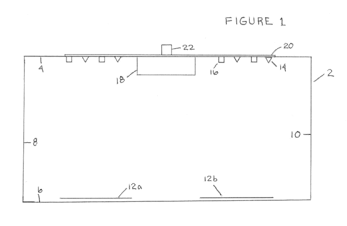
FIGURE 1 shows a full frontal view of a box construction 2 for the system.
This box
construction 2 could also be sized to be a section within a delivery shoe or
playing card
shuffler (neither shown). The box construction 2 has a top 4, A BOTTOM 6, A
LEFT SIDE
8 AND A RIGHT SIDE 10. One or more playing cards 12a and 12b may lie on the
bottom
6 of the box construction 2. A series of infrared emitters (triangles 14) and
ultraviolet
emitters (squares 16) are shown distributed along the lower inside surface of
the top 4. A
camera/sensor box (with sensing capability matching or including the output of
emitters
14 and 16) extends below the farthest extension of the emitters 14 and 16. A
signal
conducting system (20) such as wires, plates, panels and the like carries
signals between
components. An I/O port to carry signals to a processor or logic system (not
shown) is in
communication with the signal conducting system (20).
The original signals (reflected radiation) captured by the sensors is then
converted to data that
can be displayed (or even just analyzed by a processor configured with
software). An aspect
of the technology can be to merely display an image of the back of the playing
card(s) so that
markings can be visually inspected for, or to have the captured image of the
back of the card
CA 02914380 2015-12-02
WO 2014/189997
PCT/US2014/038887
16
visually or processor compared with a stored image of the back of that format
of playing
card. These stored images can either be within a look-up table of a large
number of playing
cards in the processor or accessed from a distal library for the specific
cards used), or one or
more images (to provide a standard image) can be made of the backs of playing
cards at the
beginning of a session to create an comparison image for that card set. A
"standard" image
of the back of playing cards can be important where manufacturing defects
might be present.
Slight rotations of the printed images, smears, discolorations, poor inking
and the like can be
as effective readable markings for individual playing cards as intentionally
applied markings
or daubs.
Edge markings and edge cuts can also be detected by software looking for
variations in the
linearity of sides or edges of playing cards. Surface abrasions of the backs
of the cards
(which would not require ink or pigments applied) would alter the reflection
characteristics in
areas of the cards which could be visually or tactilely detected (with or
without a player using
artificial means) and could be detected by software looking for deviations in
ideal reflection
off the backs of the playing cards.
Software is available or can be easily constructed by ordinary skill that
allows comparison of
the scanned image and the detailed image. Even the softare of the incorporated
U.S. Patent
No. 8,119,975 (which fits overlapping elements of scanned data into a single,
uniform and
meaningful image) could be easily modified to compare images as well as
identify degrees of
differences between the scanned and reference image that rises to the level of
potentially or
actually visible differences.
The system my further have: an ambient ultraviolet radiation source for
directing ultraviolet
radiation at the surface; an ultraviolet radiation sensor for capturing
reflected ambient
ultraviolet radiation; the ultraviolet radiation sensor configured to transmit
signals based on
captured reflected ultraviolet radiation; the transmitted signals from the
ultraviolet radiation
symbol providing data that contains ultraviolet image data reflected off of
the surface; a
processor configured to receive the transmitted signals from the reflected
ultraviolet
radiation, process the transmitted signals from the reflected ultraviolet
radiation and transmit
the processed transmitted signals from the reflected ultraviolet radiation in
a format that can
be displayed on a display system; and a display system configured to display
an image of the
surface from which ultraviolet radiation was reflected based on the infrared
image data and
the ultraviolet radiation data. Again, the infrared radiation source is pulsed
to reduce heating
CA 02914380 2015-12-02
WO 2014/189997
PCT/US2014/038887
17
of the surface by infrared radiation. The infrared radiation source may be
configured to pulse
the infrared radiation contemporaneously with the emitting of ultraviolet
radiation by the
ultraviolet radiation source. The processor may be configured to combine the
infrared
radiation signals and the ultraviolet radiation signals to form a composite
image on the
display system. The processor may be configured to compare that transmitted
signals with
reference data of a standard playing card back. The processor may be
configured to i)
compare the transmitted signals comprising image data of the back of a playing
card based on
reflected data and reference data stored in memory of a standard playing card
back surface
and ii) identify differences between the transmitted signals comprising image
data of the back
of a playing card based on reflected data and reference data stored in memory
and the
processor then is configured to provide image data of the comparison to either
a) highlighted
in a visual display or b) the processor identifying a degree of difference
between the image of
the back of the playing card based on the image data and the reference data,
and the processor
may be configured to determine a degree of difference between the image of the
back of the
playing card based on the image data and the reference data is identified in
b) by an
alphanumeric rating, color rating or symbolic rating. Again, the infrared
sensor may be
located at a position elevated above a surface of the gaming table, especially
where the sensor
is at a position elevated to a height wherein infrared radiation reflected
from the back surface
of the playing card at an angle of between 60 and 90 degrees (a broader range
of 30 to 90
degrees can work, but it creates a possibility of reduced quality images,
especially where
multiple sources of emitted radiation are used, and reflections may come to
sensors from
multiple emitting sources) from horizontal is received by the sensor. The
processor may be
configured to i) compare the combined transmitted signals comprising image
data of the back
of a playing card based on reflected data and reference data stored in memory
of a standard
playing card back surface and ii) identify differences between the combined
transmitted
signals comprising image data of the back of a playing card based on reflected
data and
reference data stored in memory and the processor then is configured to
provide image data
of the comparison to either a) highlighted in a visual display or b) the
processor identifying a
degree of difference between the image of the back of the playing card based
on the image
data and the reference data, and again the processor may be configured to
determine a degree
of difference between the image of the back of the playing card based on the
image data and
the reference data is identified in b) by an alphanumeric rating, color rating
or symbolic
rating. The infrared sensor is located at a position elevated above a surface
of the gaming
table, such as where the surface is provided within a housing comprising a
bottom, a top, a
CA 02914380 2015-12-02
WO 2014/189997
PCT/US2014/038887
18
back and two sides, and the ambient source of infrared radiation is provided
by at least two
infrared emitters on the top, back and/or two sides, and the infrared sensor
is supported on the
top. The surface may be provided within a housing comprising a bottom, a top,
a back and
two sides, and the ambient source of infrared radiation is provided by at
least two infrared
emitters on the top, back and/or two sides, and the ambient source of
ultraviolet radiation is
provided by at least two ultraviolet emitters on the top, back and/or two
sides, and the
infrared sensor and the ultraviolet sensor are supported on the top. The
housing may include
a card support for a set of playing cards, and a moving system for moving
individual playing
cards from the card support to the surface so that a back of the playing card
is exposed to the
transmitted infrared radiation and infrared radiation is reflected from the
back of the playing
card. This housing may be a mechanical or manual shoe, a shuffling or
randomization
system.
It is also to be noted that the system of the present technology may be used
to verify other
gaming objects to prevent fraudulent substitution of gaming objects. Invisible
dyes (again IR
or UV visible) can be embedded in or painted on (with readable codes), and the
system can
be used to verify the chips based on reading the applied code. To prevent
duplication of the
code by third parties, the code can be altered easily by regular removal (a
simple wash) and
reapplication of the invisible code. Chips may be easily coated on a regular
basis, but die
would usually have to have the ink or pigment embedded within the structure to
be viewed by
the system technology, with UV and/or IR radiation and reflection. This system
enables
more secure and faster verification of dice then the standard visual
inspection. The identical
system, with only software varied to address dice image or chip image content
can be used.
Figure 4 shows a perspective view of an alternative device 400 according to
the present
technology. The inspection device 400 is shown in an alternative embodiment
with a base
402 a top 404 and a side 406. In the middle of the top 404 is a display
monitor 408 on the top
404 which extends through the top 404 into an open volume 418 and is in
association with a
416 camera /processor combination 416. The camera/processor combination 416
has
potential and/or selective sensitivity to visible light, infrared radiation
and/or ultraviolet
radiation. This radiation and light is simultaneously or separately provided
(according to
design or control) from visible light emitter 410, ultraviolet radiation
emitter 412 and infrared
radiation emitter 414, which radiation is reflected off cards 420 (here the
back of cards, but
fronts of cards may also be used) and captured by the camera/processor 416
combination.
CA 02914380 2015-12-02
WO 2014/189997
PCT/US2014/038887
19
The camera segment receives the reflected radiation and the processor converts
it into
displayable image content for the display monitor 408. Separate components may
be
alternatively used.
As noted, the at least three ranges of radiation sensed by the
camera/processor combination
416 may be used contemporaneously, in sub-combination or sequentially and
separately. A
control panel of power button 422, infrared radiation control 424, ultraviolet
radiation control
426 and visible light control 428 are shown on the side 406. A default
operation in the
processor may allow for all three emissions to occur simultaneously upon
turning power on
with power button 422, and the other three controls 424, 426 and 426 may be
used to turn off
radiation emitters as desired. Alternatively, individual ones of the three
controls 424, 426
and 426 may be used to initiate individual, combination, sequential or
contemporaneous
emissions.
The system may screen for defects from all wavelengths at one time, and then
individual
radiation images may be used or just individual images from each radiation
emission,
reflection and capture may be used. The processor may store images for
programmed time
periods, or when one of the three controls 424, 426 and 426 is depressed, and
image of
reflection from that image may be captured by the processor and stored in
memory. The
individual images can be displayed and visually evaluated and/or the processor
may compare
the displayed image (data) content with standardized image data to determine
if there are
spurious markings on the back of the cards.
Although specific structures, components, materials, dimensions and parameters
have been
described to assure enablement of the invention, those are merely specific
examples within
the generic concepts of the present invention and should not be read as
limiting the scope of
the invention as claimed.