Note: Descriptions are shown in the official language in which they were submitted.
- 1 -
Bead wire for a tyre, tyre and manufacturing method
FIELD
[001] The invention relates to a bead wire for a tyre, to a tyre and to the
method of
manufacturing same. The invention applies to any type of tyre, notably to
tyres of
industrial vehicles selected from motor vehicles of the passenger car type,
SUVs
(Sport Utility Vehicles), two wheeled vehicles (notably bicycles, motorbikes),
heavy
vehicles such as heavy goods vehicles - i.e., metro vehicles, buses, road
haulage
vehicles (lorries, tractors, trailers), off the road vehicles ¨ agricultural
vehicles or
construction plant vehicles, aircraft, other transport or handling vehicles.
BACKGROUND
[002] A tyre comprising a crown comprising a crown reinforcement surmounted by
a
tread is known from the prior art. Two sidewalls extend the crown radially
inwards. The
tyre comprises two beads radially on the inside of the sidewalls and each
comprising
an annular reinforcing structure. The annular reinforcing structure comprises
a bead
wire substantially of revolution about an axis comprising several windings of
at least
one wire which are arranged axially next to one another over several layers
radially
superposed on one another. The wire has a substantially circular cross
section. Such
a bead wire is generally referred to as a round bead bundle. The bead wire of
the prior
art, illustrated in Figure 9, may be bare or encased in a mass of encasing
rubber.
[003] The tyre also comprises a radial carcass reinforcement extending from
the
beads to the sidewalls towards the crown. The carcass reinforcement comprises
one
or more carcass plies, at least one of these carcass plies being anchored in
each of
the beads by being folded around the annular reinforcing structure, in contact
with the
bead wire or the encasement thereof, so as to form, within each bead, a main
strand
extending radially between each bead through the sidewalls and the crown and a
turnup extending radially from each bead through each sidewall.
[004] Each bead comprises a mass of filling rubber arranged in contact with
the bead
wire or the encasement thereof, in a space delimited by the main strand and
turnup.
Each bead also comprises additional masses of rubber arranged axially on the
outside
of the turnup.
[005] When the tyre is in use on a vehicle, the tyre is mounted on a wheel
comprising a rim. The motive force of the vehicle, generally generated by the
engine
or motor thereof, is transmitted to the tyre by a transmission. If the motive
force is very
high, the tyre may slip relative to the rim such that the motive force cannot
be
transmitted in full to the tyre, thereby reducing the efficiency of the
vehicle. This
Date Recue/Date Received 2020-06-30
- 2 -
phenomenon, which is known as tyre-rim slip, is all the more penalizing when
the
vehicles are vehicles that generate a high motive force.
[006] Furthermore, during the manufacture of the tyre of the prior art, which
is
performed for example on a tyre-building drum, the bead wire is placed on the
carcass
ply and the turnup is folded around the bead wire. The carcass ply and the
bead wire
are then turned relative to one another. During this rotation, the mass of
filling rubber
and the folding of the carcass ply comprising the main strand and the turnup
rub
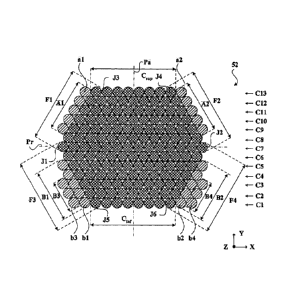
against the bead wire or the encasement thereof, thereby creating what is
referred to
as a braking torque that prevents the relative rotation of the bead wire with
respect to
the rest of the tyre, notably with respect to the carcass ply.
[007] The braking torque causes the turnup of the carcass ply and the
additional
masses of rubber arranged axially on the outside of the turnup to be placed in
compression. The braking torque also causes the main strand of the carcass ply
to be
placed in overtension. Under the effect of the overtension in the main strand,
the
windings of the bead wire, notably the windings in contact with the
overtensioned main
strand become disorganized. In addition, the friction leads to limited
relative rotation
which prevents the bead wire from adopting a correct orientation within the
tyre.
[008] When they occur, these potential problems, which have been deliberately
exaggerated in Figure 10, cause the tyre to have to be scrapped.
SUMMARY
[009] It is an object of the invention to reduce the tyre-rim slip under the
effect of the
motive force and to provide a bead wire that makes it possible to reduce the
number
of tyres that have to be scrapped as a result of a problem generated by the
braking
torque.
[010] To this end, one subject of the invention is a bead wire for a tyre
rotating about
an axis, the bead wire comprising: several windings of at least one wire which
are
arranged axially next to one another over N layers Ci radially superposed on
one
another; a basic hexagonal bead wire comprising: a radially external layer of
Ni
windings, a radially internal layer of Ni windings, two axially external and
radially
external lateral rows of N2 windings axially opposite one another, two axially
external
and radially internal lateral rows of N2 windings axially opposite one
another, with
N1=N2 + 1 or N1=N2, and two junctions each one formed by a winding common to
one of the axially external and radially external lateral rows and to one of
the axially
external and radially internal lateral rows, each winding in common and
forming each
of said junctions having no axially external adjacent winding. Also provided
are at least
two axially external and radially internal additional lateral rows, each of
said two axially
Date Recue/Date Received 2020-06-30
- 3 -
external and radially internal additional lateral rows being respectively
substantially
parallel to each of said axially external and radially internal lateral rows.
[011] A row means a juxtaposition in a substantially rectilinear main
direction of
several windings arranged so that each is in contact with the next.
[012] A lateral row means a row the main direction of which is inclined with
respect to
the axial direction of the tyre.
[013] A layer means a row extending in a main direction substantially parallel
to the
axial direction of the tyre.
[014] Two rows are substantially parallel if the main directions in which they
extend
are substantially parallel to one another.
[015] A layer of the hexagonal base bead wire is said to be "radially
external" if the
main direction in which it extends is further away from the axis of rotation
of the tyre
than those of the other layers of the hexagonal base bead wire. Conversely, a
layer of
hexagonal base bead wire is said to be "radially internal" if the main
direction in which
it extends is closer to the axis of rotation of the tyre than those of the
other layers of
the hexagonal base bead wire.
[016] A lateral row of the hexagonal base bead wire is said to be "axially and
radially
external" if the main direction in which it extends is axially and radially
further away
from the centre of the hexagonal base bead wire than those of the other
lateral rows of
the hexagonal base bead wire when progressing axially from the inside towards
the
outside of the hexagonal base bead wire and radially from the inside towards
the
outside of the tyre. Conversely, a lateral row of the hexagonal base bead wire
is said
to be "axially external and radially internal" if the main direction in which
it extends is
axially and radially further away from the centre of the hexagonal base bead
wire than
those of the other lateral rows of the hexagonal base bead wire when
progressing
axially from the inside towards the outside of the hexagonal base bead wire
and
radially from the outside towards the inside of the tyre.
[017] The same definitions will be applied to the additional coverings, rows
and
layers of the bead wire for a tyre.
[018] The bead wire according to the invention exhibits little tyre-rim slip,
thereby
improving the efficiency of the vehicle on which a tyre comprising it is
mounted.
Specifically, each axially external and radially internal additional lateral
row improves
the anchorage of the bead in the rim and reduces potential slippage between
rim and
tyre. Furthermore, the low tyre-rim slip makes it possible to avoid rubbing of
the tyre
against the rim and therefore degradation of the bead which could impair the
durability
Date Recue/Date Received 2020-06-30
CA 02914528 2015-12-04
- 4 -
of the tyre.
[019] Furthermore, the bead wire according to the invention makes it possible
to
reduce or even eliminate the number of tyres scrapped as a result of a problem
generated by the braking torque. Specifically, the bead wire according to the
invention
has a dimension in the axial direction that is relatively close to the
dimension in the
radial direction. Thus, the cross section of the bead wire according to the
invention is
relatively close to a cross section of circular overall shape, which
encourages the
relative rotation and therefore limits the braking torque, unlike the bead
wire of the
prior art.
[020] The particular shape of the bead wire according to the invention
encouraging
relative rotation is due, on the one hand, to the hexagonal shape of the base
bead
wire and, on the other hand, to the axially external and radially internal
additional
lateral rows which in combination allow the cross section of the bead wire
according to
the invention to better approximate to a cross section of circular overall
shape.
[021] Implicitly, each axially external and radially internal additional
lateral row is
arranged axially on the outside respectively with respect to each axially
external and
radially internal lateral row.
[022] A first row is said to be arranged axially on the outside of a second
row if the
main direction in which it extends is further away from the centre of the bead
wire than
that of the second row when progressing in a direction substantially parallel
to the
axial direction of the tyre. Conversely, a first row is said to be arranged
axially on the
inside of a second row if the main direction in which it extends is closer to
the centre of
the bead wire than that of the second row when progressing in a direction
substantially
parallel to the axial direction of the tyre.
[023] Advantageously, the bead wire for a tyre comprises two pairs of axially
external
and radially internal additional lateral rows respectively of N5 and N6
windings, each
axially external and radially internal additional lateral row being
substantially parallel
respectively to each axially external and radially internal lateral row.
Thanks to the two
pairs of axially external and radially internal additional lateral rows, the
tyre-rim slip of
the tyre is reduced still further.
[024] Optionally, N5N16, preferably N5>N6, and more preferably, N5=N6+2.
[025] In one embodiment, each radially internal winding of each axially
external and
radially internal additional lateral row is radially substantially aligned
with the radially
internal layer.
[026] In another embodiment, the bead wire for a tyre comprises at least one
axially
external and radially internal additional covering of windings in the overall
shape of a
P1 0-3077_PCT
CA 02914528 2015-12-04
- 5 -
U.
[027] Advantageously, the bead wire comprises such an additional covering when
N1<7 and preferably when N1<6. This is because reducing N1 leads to an
increase in
the risk of tyre-rim slip and in the pressure of the rim on each winding of
the bead wire.
It is therefore preferable to add a covering in order to reduce this risk and
better
spread the pressure applied by the rim to the bead wire.
[028] Implicitly, the windings of the axially external and radially internal
additional
covering are arranged axially on the outside of each axially external and
radially
internal lateral row and radially on the inside of the radially internal
layer.
[029] The windings of a covering are said to be arranged axially on the
outside of a
row if the main direction in which the windings of the covering extend
parallel to that of
the row is further away from the centre of the bead wire than that of the row
that they
are covering when progressing in a direction substantially parallel to the
axial direction
of the tyre.
[030] The windings of a covering are said to be arranged radially on the
inside of a
layer if the main direction in which the windings of the covering extend
parallel to that
of the layer is closer to the axis of the tyre than that of the layer that
they are covering
when progressing in a direction substantially parallel to the radial direction
of the tyre.
[031] For preference, the axially external and radially internal additional
covering
comprises:
- a radially internal additional layer of N7 windings, and substantially
parallel to the
radially internal layer,
- at least two axially external and radially internal additional lateral rows.
[032] Implicitly, the radially internal additional layer is arranged radially
on the inside
of the radially internal layer.
[033] A first layer is said to be arranged radially on the inside of a second
layer if the
main direction in which it extends is closer to the axis of the tyre than that
of the
second layer in a direction substantially parallel to the radial direction of
the tyre.
[034] For preference, the axially external and radially internal additional
covering
comprises a single radially internal additional layer of N7 windings
substantially
parallel to the radially internal layer.
[035] For preference, N7=N1+1.
[036] Advantageously, with each axially external and radially internal
additional
lateral row comprising N5 windings, N5.5N2, preferably N5=N2, N5+1=N2 or
N5+2=N2.
[037] Preferably, max(L1)=N-1, max(Li)=N or max(L1)=N+1 where L, is the number
of
p10-3077_pc-r
CA 02914528 2015-12-04
- 6 -
windings of each layer C,, i varying from 1 to N inclusive. Thus, the bead
wire has a
dimension in the axial direction that is as close as possible to the dimension
in the
radial direction.
[038] Advantageously, the bead wire for a tyre comprises at least one layer Ck
where
k 11, N[ such that Lk+1 > Lk and Lk < Lk_i. Thus, the bead wire is more
robust when
handled. Specifically, by virtue of this feature, pressure is brought to bear
on several
axially external windings, in this instance those of the layers Ck+i and Ck-i,
unlike in the
bead wire of the prior art on which pressure is brought to bear on just one
axially
external winding. Thus the load applied to each of these axially external
windings and
the risk of disorganizing the bead wire are limited.
[039] For preference, for each layer Ck where k C ]1, N[ such that Lk+i > Lk
and Lk <
Lk+1=Lk+1 and Lk+1=1-k-1=
[040] Optionally, the bead wire for a tyre also comprises at least two axially
and
radially external additional lateral rows, each axially and radially external
additional
lateral row being substantially parallel respectively to each axially and
radially external
lateral row.
[041] This then further reduces the braking torque during the method of
manufacture.
Specifically, the specific shape of the bead wire further encourages relative
rotation
because, on the one hand, of the hexagonal shape of the base bead wire and, on
the
other hand, of the axially and radially external additional lateral rows
which, in
combination, allow the cross section of the bead wire according to the
invention to
better approximate to a cross section of circular overall shape.
[042] Implicitly, each axially and radially external additional lateral row is
arranged
axially on the outside respectively of each axially and radially external
lateral row.
[043] For preference, the bead wire comprises two, and only two, axially and
radially
external additional lateral rows, each axially and radially external
additional lateral row
being substantially parallel respectively to each axially and radially
external lateral row.
[044] In one embodiment, each radially external winding of each axially and
radially
external additional lateral row is radially substantially aligned with the
radially external
layer.
[045] In another embodiment, the bead wire comprises at least one axially and
radially external additional covering of windings in the overall shape of a U.
[046] Advantageously, the covering thus allows the cross section of the bead
wire to
approximate still further to a cross section of circular overall shape.
[047] Implicitly, the windings of the axially and radially external additional
covering
are arranged axially on the outside of each axially and radially external
lateral row and
P1 0-3077_PCT
CA 02914528 2015-12-04
- 7 -
radially on the outside of the radially external layer.
[048] The windings of a covering are said to be arranged radially on the
outside of a
layer if the main direction in which the windings of the covering extend
parallel to that
of the layer is further away from the axis of the tyre than that of the layer
they are
covering when progressing in a direction substantially parallel to the radial
direction of
the tyre.
[049] Advantageously, the axially and radially external additional covering
comprises:
- a radially external additional layer of N4 windings, substantially parallel
to the
radially external layer,
- at least the two axially and radially external additional lateral rows.
[050] Implicitly, the radially external additional layer is arranged radially
on the
outside of the radially external layer.
[051] A first layer is said to be arranged radially on the outside of a second
layer if
the main direction in which it extends is further away from the axis of the
tyre than that
of the second layer in a direction substantially parallel to the radial
direction of the tyre.
[052] For preference, the axially and radially external additional covering
comprises
a single radially external additional layer of N4 windings, substantially
parallel to the
radially external layer.
[053] Advantageously, in order for the cross section of the bead wire to
approximate
still further to a cross section of circular overall shape, max(L,)-N15.6, i
varying from 1
to N. Preferably, max(L,)-N152, i varying from 1 to N for max(L)s9 and max(L,)-
N156,
i varying from 1 to N for max(L)>9.
[054] For preference, N4=N1+1. Thus, the additional covering espouses the
overall
shape of the hexagonal base bead wire, encouraging relative rotation of the
carcass
ply on the radially external additional layer.
[055] Advantageously, with each axially and radially external additional
lateral row
comprising N3 windings, N35N2, preferably N3=N2, N3+1=N2 or N3+2=N2.
[056] N35N2, preferably N3=N2, N3+1=N2 or N3+2=N2. Similarly, the additional
covering espouses the overall shape of the hexagonal base bead wire thereby
encouraging relative rotation of the carcass ply on the axially and radially
external
additional lateral rows.
[057] According to other optional features of the bead wire for a tyre which
features
are independent of one another:
- The hexangonal base bead wire has an axial plane of symmetry.
- The hexagonal base bead wire has a radial plane of symmetry.
- The bead wire for a tyre has an axial plane of symmetry.
P10-3077_PCT
-8-
- The bead wire for a tyre is obtained by successive superpositions of the
N layers Cõ
each layer C, being obtained by successive axial windings of at least one
wire.
- The bead wire for a tyre comprises a single wire forming the windings of
the N layers
C,.
- The or each wire is made of metal.
- The or each wire is made of a carbon steel containing between 0.6 and 0.9
wt% of
carbon.
- The or each wire has a substantially circular cross section.
- The or each wire has a diameter of between 1 and 3.2 mm, preferably
between 1.2 and
2.2 mm and more preferably between 1.2 and 2 mm.
- N 5, preferably N 7 and more preferably N 9.
- max(L) 4, preferably max(L) 6 and more preferably, max(L) 9.
- The total number of windings of the bead wire is greater than or equal to
30, preferably
greater than or equal to 50 and more preferably greater than or equal to 70.
- Lk-E1 - Lk 1=1 for i varying from 1 to N inclusive.
[058] Another subject of the invention is a tyre comprising:
- at least one bead comprising at least one bead wire for a tyre as defined
hereinabove,
- a carcass reinforcement comprising at least one carcass ply anchored in
each bead by
a turnup around the bead wire.
[059] Another subject of the invention is a method of manufacturing a tyre as
defined
hereinabove, in which method:
- the bead wire is placed on the carcass ply,
- part of the carcass ply is folded around the bead wire, and
- the carcass ply and the bead wire are turned relative to one another.
BRIEF DESCRIPTION OF THE DRAWINGS
[060] The invention will be better understood from reading the following
description,
given solely by way of nonlimiting example and made with reference to the
drawings in
which:
Figure 1 is a view in radial section of a tyre according to the invention;
Figure 2 is a detailed view in cross section of region I of the tyre of Figure
1;
Figure 3 is a view in cross section of a bead wire according to a first
embodiment
of the invention;
Figures 4a, 4b, 4c and 4d are views in cross section illustrating various
steps in
the method of manufacture according to the invention;
Figures 5 to 8 are views similar to that of Figure 3 of bead wires
respectively
according to second, third, fourth and fifth embodiments;
Date Recue/Date Received 2020-06-30
-9-
-
Figure 9 is a view similar to that of Figure 3 of a bead wire of the prior
art;
Figure 10 is a view similar to that of Figure 2 of a bead of a tyre of the
prior art
comprising the bead wire of Figure 9.
DETAILED DESCRIPTION
[061] The tyre according to the invention has a toroidal overall shape about
an axis of
rotation. This axis of rotation defines the axial direction.
[062] When using the term "radial" it is appropriate to make a distinction
between the
various different uses made of this word by those skilled in the art when
referring to tyres.
[063] Firstly, the expression refers to a radius of the tyre. It is in this
sense that an
element A is said to be "radially inside" an element B (or "radially on the
inside of" the
element B) if it is closer to the axis of rotation of the tyre than is the
element B.
Conversely, an element C is said to be "radially outside" an element D (or
"radially on the
outside of' the element D) if it is further away from the axis of rotation of
the tyre than is
the element D. Progress is said to be "radially inwards (or outwards)" when it
is in the
direction towards smaller (or larger) radii.
[064] Secondly, a reinforcing element or a reinforcement is said to be
"radial" when the
reinforcing element or the reinforcing elements of the reinforcement make an
angle
greater than or equal to 65 and less than or equal to 90 with the
circumferential
direction.
[065] Thirdly, a "radial section" or "radial cross section" here means a
section or cross
section on a plane containing the axis of rotation of the tyre.
[066] An "axial" direction is a direction parallel to the axis of rotation of
the tyre. An
element E is said to be "axially inside" an element F (or "axially on the
inside of" the
element F) if it is closer to the midplane of the tyre than is the element F.
Conversely, an
element G is said to be "axially outside" an element H (or "axially on the
outside of" the
element H) if it is further from the midplane of the tyre than is the element
H.
[067] The "midplane" of the tyre is the plane which is perpendicular to the
axis of rotation
of the tyre and lies equal distances from the annular reinforcing structures
of each bead.
[068] A "circumferential" direction is a direction which is perpendicular both
to a radius of
the tyre and to the axial direction.
[069] EXAMPLE OF A TYRE AND BEAD WIRE ACCORDING TO THE INVENTION
[070] The figures that follow depict directions X, Y, Z corresponding to the
usual axial
(X), radial (Y) and circumferential (Z) orientations of a tyre.
[071] Figures 1 and 2 depict an example of a tyre according to the invention
and
Date Recue/Date Received 2020-06-30
CA 02914528 2015-12-04
- 10 -
denoted by the general reference 10. The tyre 10 is preferably intended for an
industrial vehicle selected from motor vehicles of the passenger car type,
SUVs (Sport
Utility Vehicles), two-wheeled vehicles (notably bicycles, motorbikes), heavy
vehicles
such as heavy goods vehicles - i.e. metro vehicles, buses, road haulage
vehicles
(lorries, tractors, trailers), off the road vehicles ¨ agricultural vehicles
or construction
plant vehicles, aircraft, other transport or handling vehicles. In this
particular instance,
the tyre 10 is intended for an agricultural vehicle, for example a tractor.
[072] The tyre 10 has a nominal rim diameter as defined by the ETRTO (European
Tyre and Rim Technical Organisation) of between 24 and 54 inches endpoints
inclusive (between 60.96 cm and 137.16 cm). The tyre 10 has a nominal aspect
ratio
as defined by the ETRTO of between 0.7 and 0.9, endpoints inclusive.
[073] The tyre 10 comprises a crown 12 comprising a crown reinforcement 14
comprising one or more crown plies 16 of reinforcing elements. The crown
reinforcement 14 is surmounted by a tread 18. The crown reinforcement 14 is
arranged radially in the inside of the tread 18. Two sidewalls 20 extend the
crown 12
radially inwards. The tyre 10 comprises two beads 22 radially on the inside of
the
sidewalls 20 and each comprising an annular reinforcing structure 24.
[074] The tyre 10 also comprises a radial carcass reinforcement 26. The
carcass
reinforcement 26 extends from the beads 22 through the sidewalls 20 towards
the
crown 12. The carcass reinforcement 26 comprises one or more carcass plies 28,
at
least one of these carcass plies 28 being anchored in each of the beads 22 by
being
folded 30 around the annular reinforcing structure 24 to form, within each
bead 22, a
main strand 32 extending radially between each bead 22 through the sidewalls
20 and
the crown 12, and a turnup 34 extending radially from each bead 22 through
each
sidewall 20, the radially external end 36 of the turnup 34 being situated
radially on the
outside of the annular reinforcing structure 24 and axially on the outside of
the main
strand 32.
[075] The tyre 10 also comprises an airtight inner ply 38 arranged radially
and axially
on the inside of the carcass reinforcement 26. The inner ply 38 extends
between each
bead 22, passing via the sidewalls 20 and the crown 12.
[076] Each bead 22 comprises, in addition to the annular reinforcing structure
24, a
mass 40 of filling rubber arranged in a space delimited by the main strand 32
and the
turnup 34. Each bead 22 also comprises a first mass 42 of cushioning rubber
protecting the bead 22 around the folding 30 of the carcass reinforcement 26.
[077] In addition, each bead 22 also comprises a mass 44 of filling rubber
arranged
axially outside the carcass reinforcement 26, particularly axially outside the
turnup 34.
P1 0-3077_PCT
CA 02914528 2015-12-04
- 11 -
Each sidewall 20 comprises a mass 46 of axially external rubber delimiting an
axially
external surface 48 of the sidewall 20 and arranged axially on the outside of
the mass
44 of filling rubber. Finally, each bead 22 comprises a second mass 50 of
cushioning
for the bead 22, arranged axially between the mass 44 of filling rubber and
the axially
external mass 46 of rubber of the sidewall 20.
[078] Each annular reinforcing structure 24 comprises an annular bead wire 52
coated in an encasing mass 54, for example containing rubber. The bead wire 52
is
arranged radially on the inside of the mass 40 of filling rubber. The bead
wire 52 is in
accordance with a first embodiment of the invention.
[079] Figure 3 depicts the bead wire 52 according to the first embodiment of
the
invention.
[080] The bead wire 52 has an overall shape of revolution about the axis of
revolution of the tyre 10 which is substantially parallel to the axial
direction X.
[081] The bead wire 52 has an axial plane of symmetry Pa, namely a plane of
symmetry that is perpendicular to the axial direction X (parallel to the
midplane M).
[082] The bead wire 52 comprises P windings of at least one wire which are
arranged axially next to one another over N layers C, radially superposed on
one
another. The bead wire 52 is obtained by successive superpositions of the N
layers C,
with i varying from 1 to N inclusive, each layer C, being obtained by axially
successive
windings of at least one wire. The total number of windings P of the bead wire
52 is
greater than or equal to 30, preferably greater than or equal to 50, and more
preferably, greater than or equal to 70 and here P=166.
[083] In the example of Figure 3, the bead wire 52 comprises P windings of a
single
wire. For preference, the wire is made of metal, has a substantially circular
cross
section and advantageously a diameter of between 1 and 3.2 mm, preferably
between
1.2 and 2.2 mm, and more preferably, between 1.2 and 2 mm, here a diameter
equal
to 1.55 mm. The wire is made of a carbon steel containing 0.7 wt% of carbon.
[084] The bead wire 52 thus comprises, starting from the radially innermost
layer C1
to the radially outermost layer ON, N radially successive layers with N .? 5,
preferably
N 7 and more preferably N l= 9, and here N=13.
[085] Table 1 below collates the number of windings Li of each layer C. The
maximum number of windings max(Li) of the N layers C, is such that max(L) 4,
preferably max(L,) 6, and more preferably, max(L) 9. Here, max(L)=14. In
addition,
max(Li)=N-1, max(L)=N or max(L)=N+1. Here, max(L1)=N+1.
P 1 0-3077_PCT
=
CA 02914528 2015-12-04
- 12 -
Number of the Number of Number of the Number of
layer Ci windings Li layer Ci windings Li
Cl 12 C8 13
02 13 09 14
03 14 C10 13
C4 13 C11 12
05 14 012 11
06 13 C13 10
C7 14
Table 1
[086] The bead wire 52 comprises at least one layer Ck where k , N[
such that
> Lk and Lk < Lk_i. In addition, for i varying from 1 to N inclusive, j Lk+1
Lk I =1.
Furthermore, for each layer Ck, where k 11, N[ such that Lk+i > Lk and Lk <
Lk-1,
Lk+1.--Lk+1 and Lk+1=l_k_1. Here, each layer 04, C6 and C6 comprises
1_4=1_6=1_8=13
windings and each layer 03, 05, C7 and C9 comprises L3=L5=L7=L9=14 windings.
[087] The bead wire 52 comprises a base bead wire 56 of which the windings are
depicted in the various Figures 3 and 5-8 by circles filled with a pattern of
crosshatching. The bead wire 56 has an axial plane of symmetry Pa, namely a
plane
of symmetry perpendicular to the axial direction X (parallel to the midplane
M). The
bead wire 56 also has a radial plane of symmetry Pr, namely a plane of
symmetry
perpendicular to the radial direction Y.
[088] The base bead wire 56 has a hexagonal shape, namely a shape comprising
six sides each one defined by a layer or a row of windings each one meeting
the next
at six junctions J1 to J6 each one formed by a winding that a layer and a row
or two
rows that form the corresponding junction have in common.
[089] Thus, the base bead wire 56 comprises a radially internal side defined
by a
radially internal layer C,õf of Ni windings and a radially external side
defined by a
radially external layer Csup of Ni windings. The base bead wire 56 also
comprises two
radially external axial sides each one defined by an axially and radially
external lateral
row Fl, F2 of N2 windings. The base bead wire 56 additionally comprises two
radially
internal axial sides each one defined by an axially external and radially
internal lateral
row F3, F4 of N2 windings. The pairs of radially external and internal axial
sides are
axially opposite one another, namely face one another about the axial
direction X.
[090] N1=N2+1 or N1=N2 and here N1=N2-1-1. Specifically, N1=8 and N2=7.
[091] Each junction J1, J2 is formed by a winding that each axially and
radially
P10-3077_PCT
CA 02914528 2015-12-04
- 13 -
external lateral row Fl, F2 and each axially external and radially internal
lateral row
F3, F4 have in common. Each winding in common that forms each junction J1, J2
has
no winding of the wire axially on the outside of it.
[092] Each junction J3, J4 is formed by a winding that each axially and
radially
external lateral row Fl , F2 and the radially external layer Csup have in
common.
[093] Each junction J5, J6 is formed by a winding that each axially external
and
radially internal lateral row F3, F4 and the radially external layer Cinf have
in common.
[094] The bead wire 52 also comprises at least two axially and radially
external
additional lateral rows Al, A2 of N3 windings. Each axially and radially
external
additional lateral row Al, A2 is substantially parallel respectively to each
axially and
radially external lateral row Fl, F2.
[095] Each axially and radially external additional lateral row Al, A2 is
arranged
axially on the outside respectively of each axially and radially external
lateral row Fl,
F2. Here N3=5.
[096] In this embodiment, each axially and radially external additional
lateral row Al,
A2 comprises a radially external winding al, a2 radially substantially aligned
with the
radially external layer Csup.
[097] N351\12 and for preference N3=N2, N3+1=N2 or N3+2=N2. In this instance,
N3+2=N2.
[098] In this embodiment, the bead wire 52 also comprises at least two axially
external and radially internal additional lateral rows B1, 62, B3, 34. The
bead wire 52
comprises two pairs of axially external and radially internal additional
lateral rows, Bl ,
B2 on the one hand, and B3, B4 on the other hand, of N5 and N6 windings
respectively. Each axially external and radially internal additional lateral
row B1, B3 on
the one hand, and 62, B4 on the other hand, is substantially parallel
respectively to
each axially external and radially internal lateral row F3, F4.
[099] Each axially external and radially internal additional lateral row, B1 ,
B3 on the
one hand, and B2, 64 on the other hand, is arranged axially on the outside
respectively of each axially external and radially internal lateral row B3,
F4. Each
axially external and radially internal additional lateral row B3, B4 is
arranged axially on
the outside respectively of each axially external and radially internal
additional lateral
row 131, 62.
[0100] In this embodiment, each axially external and radially internal
additional lateral
row B1 , B2, B3, 134 comprises a radially internal winding bl, b2, b3, b4
radially
substantially aligned with the radially internal layer Cinf.
[0101] N5?_N6, preferably N5>N6 and here N5=N6+2 with N5=5 and N6=3. Also,
P10-3077_P CT
CA 02914528 2015-12-04
- 14 -
N5N12, preferably N5=N2, N5+1=N2 or N5+2=N2 and here N5+2=N2.
[0102] Also, max(1..)-N156.
[0103] The windings of the additional lateral rows Al, A2, B1, B2, B3 and B4
are
depicted as circles filled with a pattern of parallel hatching.
[0104] EXAMPLE OF THE METHOD ACCORDING TO THE INVENTION
[0105] A method of manufacturing a tyre according to the invention will now be
described with reference to Figures 4a to 4d.
[0106] First of all, in a first tyre-building phase, the various plies, masses
of rubber
and other elements described hereinabove are built up to form a green tyre on
a tyre-
building drum already known to those skilled in the art.
[0107] Thus, the first mass 42 of cushioning rubber, airtight inner ply 38,
one or more
carcass plies 28 intended to be anchored in the bead 20, the mass 40 of
filling rubber
and the annular reinforcing structure 24 comprising the bead wire 52 and the
encasing
mass 54 are laid in succession and in that order. Thus, the bead wire 52 has
been
placed on the carcass ply or plies 28. This results in the intermediate green
tyre form
depicted in Figure 4a.
[0108] The first mass 42 of cushioning rubber and part of the carcas ply or
plies 28, in
this instance the turnup 34, is then folded around the annular reinforcing
structure 24.
This then results in the intermediate green tyre form depicted in Figure 4b.
[0109] Next, the mass 44 of filling rubber, the second cushioning mass 50 and
finally
the axially external mass 46 of rubber delimiting the axially external surface
48 of the
sidewall 20 are placed in succession and in that order. This then results in
the
intermediate green tyre form depicted in Figure 4c.
[0110] Finally, the carcass ply or plies 28 and the bead wire 52 are turned
relative to
one another. In this instance, the entire intermediate green tyre form with
the
exception of the annular reinforcing structure 24 is turned about the latter
which
remains substantially fixed during rotation. As an alternative, the bead wire
52 could
be turned keeping the remainder of the green tyre form fixed. This then
results in the
intermediate green tyre form depicted in figure 4d. It may be noted that
following the
rotation, the bead wire 52 has the same orientation that it had before
rotation and that
the various plies and masses of rubber have not been deformed under the effect
of
the rotation.
[0111] In a subsequent second finishing phase, the crown 12 and the tread 18
are
added to the intermediate green tyre form previously obtained.
[0112] In a third, curing, phase, the final green tyre is cured in order to
obtain the
P10-3077_PCT
CA 02914528 2015-12-04
=
- 15 -
cured tyre.
[0113] OTHER EXAMPLES OF BEAD WIRES ACCORDING TO THE INVENTION
[0114] Figures 5, 6, 7 and 8 depict bead wires according to other embodiments
of the
invention. In these figures, elements similar to those of Figure 3 are denoted
by
identical references.
[0115] Figure 5 depicts a bead wire according to a second embodiment of the
invention.
[0116] Unlike the bead wire according to the first embodiment, the bead wire
52
according to the second embodiment comprises N=9 layers and P=76 windings.
[0117] Table 2 below collates the number of windings L, of each layer Q.
max(L1)=N+1=10.
Number of the Number of Number of the Number of
layer Ci windings Li layer Ci windings Li
Cl8 C6 9
C2 9 C7 8
C3 10 C8 7
04 9 C9 6
=
05 10
Table 2
[0118] The bead wire 52 comprises at least one layer Ck where k C 11, N[ such
that
Lk+i > Lk and Lk < Lk1. Furthermore, for each layer Ck where k C ]1, N[ such
that
Lk+i > Lk and Lk < Lk, Lk+1=Lk+1 and Lk+1=Lk_1. Here, the layer 04 comprises I-
4=9
windings and each layer C3, 05 comprises L3=L5=10 windings.
[0119] The base bead wire 56 is such that N1=N2+1. Specifically, N1=6, N2=5.
[0120] Unlike the bead wire of the first embodiment, the bead wire 52
according to the
second embodiment comprises just one pair of axially external and radially
internal
additional lateral rows B1, B2 of N5=3 windings.
[0121] N55N2, preferably N5=N2, N5+1=N2 or N5+2=N2 and here N5+2=N2.
[0122] Also, max(L)-N16.
[0123] Figure 6 depicts a bead wire according to a third embodiment of the
invention.
[0124] The bead wire 52 according to the third embodiment comprises N=7 layers
and
P10-3077_PCT
CA 02914528 2015-12-04
- 16 -
P=42 windings,
[0125] Table 3 below collates the number of windings L, of each layer C.
max(L)N7.
Number of the Number of Number of the Nombre
layer Ci windings Li layer CI d'enroulements Li
Cl 5 05 7
C2 6 06 6
03 7 C7 5
C4 6
Table 3
[0126] The bead wire 52 comprises at least one layer Ck where k C )1, N[ such
that
Lk+i > Lk and Lk < Lk.i. Furthermore, for each layer Ck where k C ]1, N[ such
that
Lk+i > Lk and Lk < Lk_i, Lk+1=Lk+1 and Lk+1-----Lk_1. Here, the layer C4
comprises L4=6
windings and each layer 03, 05 comprises L3=L5=7 windings.
[0127] The bead wire 52 according to the third embodiment is such that
N1=N2+1.
Specifically, N1=4 and N2=3. Additionally, N351\12 and here N3=N2=3.
Furthermore,
N4=N1+1 with N4=5 and N1=4.
[0128] Unlike the bead wire according to the first embodiment, the bead wire
52
according to the third embodiment comprises at least one axially and radially
external
additional covering Dsõp of windings in the overall shape of a U. The windings
of the
axially and radially external additional covering Dsup are depicted as circles
filled with a
pattern of parallel hatching.
[0129] The windings of the axially and radially external additional covering
Dsup are
arranged axially on the outside of each axially external lateral row and
radially on the
outside of the radially external layer Csup.
[0130] The axially and radially external additional covering Dsup comprises a
radially
external additional layer Esup of N4 windings, substantially parallel to the
radially
external layer Cõp. The additional layer Eõ,p is radially arranged on the
outside of the
radially external layer Cõp. The bead wire 52 according to the third
embodiment is
such that N4=N1+1.
[0131] The axially and radially external additional covering Dsup also
comprises two
axially and radially external additional lateral rows Al, A2 of N3 windings.
Each
additional lateral row Al, A2 is substantially parallel respectively to each
axially and
radially external lateral row Fl, F2. Each axially and radially external
additional lateral
P10-3077_P CT
CA 02914528 2015-12-04
- 17 -
row Al, A2 is arranged axially on the outside respectively of each axially and
radially
external lateral row Fl, F2.
[0132] Here, N3=4. N35N2 and here N3=N2.
[0133] Furthermore, the bead wire 52 according to the third embodiment
comprises at
least one axially external and radially internal additional covering Drif of
windings in the
overall shape of a U. The windings of the axially external and radially
internal
additional covering Dinf are depicted as circles filled with a pattern of
parallel hatching.
[0134] The windings of the axially external and radially internal additional
covering Dinf
are arranged axially on the outside of each axially internal and radially
external lateral
row and radially on the inside of the radially internal layer C.
[0135] The axially external and radially internal additional covering Dinf
comprises a
radially internal additional layer Einf of N7 windings substantially parallel
to the radially
internal layer Cf. The radially internal additional layer Enf is arranged
radially on the
inside of the radially internal layer C.f.
[0136] The axially external and radially internal additional covering Dinf
also comprises
two axially external and radially internal additional lateral rows B1, B2 of
N5 windings.
This axially external and radially internal additional lateral row B1, B2 is
substantially
parallel respectively to each axially external and radially internal lateral
row F3, F4.
Each axially external and radially internal additional lateral row B1, 62 is
axially
arranged on the outside respectively of each axially external and radially
internal
lateral row F3, F4.
[0137] N55.N2, and here, N5=N2=3 and N7=N1+1 with N7=5.
[0138] Also, max(U)-N1.5.6 and preferably max(Li)-N152.
[0139] Figure 7 depicts a bead wire according to a fourth embodiment of the
invention.
[0140] The bead wire 52 according to the fourth embodiment comprises N=7
layers
and P=35 windings.
[0141] Table 4 below collates the number of windings L, of each layer C.
max(U)=N-
1=6.
P10-3077_PCT
CA 02914528 2015-12-04
- 18 -
Number of the Number of Number of the Number of
layer Ci windings Li layer Ci windings Li
Cl 4 05 6
02 5 06 5
03 6 07 4
04 5
Table 4
[0142] The bead wire 52 comprises at least one layer Ck where k C 11, N[ such
that
Lk+i > Lk and Lk < Lk_i. Furthermore, for each layer Ck where k C 11, N[ such
that
Lk+i > Lk and Lk < Lk1, Lk+1=Lk+1 and Lk+1=Lk_1. Here, the layer C4 comprises
I-4=5
windings and each layer 03, 05 comprises L3=L5=6 windings.
[0143] Unlike the bead wire 52 according to the third embodiment, N1=N2=3. In
addition, N3a12 and here N3=N2=3. Furthermore, N4=N1+1 with N4=4 and N1=3.
Also, N55N2 and here N5=N2=3 and N7=N1+1 with N7=4.
[0144] Also, max(L,)-N1..5.6 and preferably N1-max(L)52.
[0145] Figure 8 depicts a bead wire according to a fifth embodiment of the
invention.
[0146] The bead wire 52 according to the fifth embodiment comprises N=12
layers
and P=35 windings. N1=N2=6.
[0147] Table 5 below collates the number of windings L, of each layer C.
max(L,)=N=12.
Number of the Number of Number of the Number of
layer Ci windings Li layer Ci windings Li
Cl 10 07 12
02 11 08 11
03 12 09 10
04 11 010 9
05 12 C11 8
06 11 012 7
Table 5
P1 0-3077_PCT
CA 02914528 2015-12-04
- 19 -
[0148] The bead wire 52 comprises at least one layer Ck where k 11, N[ such
that
Lk+i > Lk and Lk < Lk_i. Furthermore, for each layer Ck, where k 11, N[ such
that Lk+1
> Lk and Lk < Lk-i, Lk+1=Lk+1 and Lk+1=Lk_i. Here, each layer 04, 06 comprises
L4=L6=11 windings and each layer C3, C5, 07 comprises L3=L5=L7=12 windings.
[0149] In a similar way to the bead wire according to the third and fourth
embodiments
of Figures 6 and 7, the bead wire 52 according to the fifth embodiment
comprises an
axially and radially external additional covering Dõp of windings in the
overall shape of
a U.
[0150] The axially and radially external additional covering Dspp comprises a
radially
external additional layer Esup of N4 windings, substantially parallel to the
radially
external layer Cspp. The radially external additional layer Eõ is radially
arranged on
the outside of the radially external layer Csup.
[0151] The axially and radially external additional covering Dspp also
comprises two
axially and radially external additional lateral rows Al, A2 of N3 windings
substantially
parallel respectively to each axially and radially external row Fl, F2. Each
axially
external and radially internal additional lateral row Al, A2 is axially
arranged on the
outside respectively of each axially external and radially internal lateral
row Fl, F2.
[0152] The bead wire 52 according to the second embodiment is such that N35N2
and here N3=N2=6. Furthermore N4=N1+1 with N4=7 and N1=6.
[0153] In a similar way to the bead wire according to the first embodiment,
the bead
wire 52 according to the fifth embodiment also comprises two pairs of axially
external
and radially internal additional lateral rows, B1, B2 on the one hand, and B3,
B4 on the
other hand, respectively of N5 and N6 windings.
[0154] In this embodiment, each axially external and radially internal
additional lateral
.. row B1, B2, B3, B4 comprises a radially internal winding b1, b2, b3, b4
radially
substantially aligned with the radially internal layer C.
[0155] The axially external and radially internal additional lateral rows, B1,
B2, on the
one hand, and B3, B4 on the other hand, are respectively substantially
parallel to each
axially external and radially internal row F3, F4.
[0156] Each axially external and radially internal additional lateral row, B1,
B2 on the
one hand, and B3, B4 on the other hand, is axially arranged on the outside
respectively of each axially external and radially internal lateral row F3,
F4.
[0157] N5?.N6, preferably N5>N6 and here N5=N6+2 with N5=5 and N6=3. Also,
N55N2 and here N5+1=N2.
[0158] Also max(L,)-N156.
P10-3077_PCT
CA 02914528 2015-12-04
- 20 -
[0159] COMPARATIVE TESTS AND TRIALS
[0160] Performance of the method of manufacture
[0161] Figure 9 depicts a bead wire 100 of the prior art. This bead wire has
none of
the features essential to the invention that allow easy relative rotation of
the bead wire
with respect to the carcass ply.
[0162] Figure 10 depicts a tyre 200 of the prior art comprising a bead wire
100 and
manufactured by employing steps similar to the steps described with reference
to
Figures 4a to 4d. The tyre 200 has defects that have been deliberately
exaggerated
for the purposes of illustrating the advantages of the invention.
[0163] Note the presence of the region in which the turnup 34' and the masses
of
rubber 44', 46' and 50' arranged axially on the outside of the turnup have
been placed
in compression. The overtensioning of the main strand 32' causes the windings
in
contact with the main strand 32' but also those in contact with the turnup 34'
to
become disorganized. In addition, the relative rotation falls short by an
angle a.
[0164] Comparing Figures 2 (or 4d) and 10, it may be noted that use of the
method of
manufacture of the tyre according to the invention leads to a tyre that does
not have
the potential defects unlike the tyre 200.
[0165] Tyre-rim slip performance
[0166] The tyre-rim slip performance of each tyre was tested. Specifically, in
order for
the tyre to be able to transfer all of the force applied by the engine or
motor of the
vehicle to the ground, it is preferable that the tyre-rim slip be as low as
possible.
[0167] The co-efficient of friction p between the rim and tyre is therefore
measured. To
do so, use is made of a vehicle with a total mass of 2 tonnes provided with
two tyres to
be tested. A weight of equal mass, in this instance 2 tonnes, is then hauled
over
bitumen. Between the weight that is to be hauled and the vehicle is positioned
a
dynamometric sensor that enables the force F, expressed in kg applied by the
vehicle
to the weight to be hauled to be measured as the tyre begins to slip relative
to the rim.
Thus, for a force F=500 kg applied in order to cause the tyre to slip relative
to the rim,
a co-efficient of friction p=0.5 is obtained. A score of between 0 and 5.0 is
assigned
according to the force recorded, zero indicating a tyre exhibiting a great
deal of tyre-
rim slip and 5 indicating a tyre with the best possible tyre-rim slip
performance. The
results of these tests are collated in Table 6 below.
Bead wire Score Bead wire Score
P10-3077_PCT
CA 02914528 2015-12-04
- 21 -
100 5 52 ¨ Fig.6 5
52 ¨ Fig.3 5 52 ¨ Fig.7 4
52 ¨ Fig. 5 5 52 ¨ Fig.8 5
Table 6
[0168] The scores of 4 and 5 are considered to indicate a low tyre-rim slip
and
therefore that the corresponding tyres meet the required tyre-rim slip
performance
criterion. Note that all the tyres according to the invention have a score of
4 or higher.
[0169] Thus, the tyres according to the invention make it possible to avoid
the need to
take special precautions during the method of manufacture and exhibit low tyre-
rim
slip.
[0170] The invention is not restricted to the embodiments described
hereinabove.
[0171] Thus, the axially external and radially internal additional covering
DInt may
comprise several radially internal additional layers Einf substantially
parallel to the
radially internal layer Cm as well as several pairs of axially external and
radially
internal additional lateral rows.
[0172] The features of the various embodiments described hereinabove may be
combined in so far as they are mutually compatible.
P I 0-3077_P CT