Note: Descriptions are shown in the official language in which they were submitted.
CA 02914558 2015-12-11
GUIDANCE SYSTEM FOR A MINING MACHINE
CROSS-REFERENCE TO RELATED APPLICATIONS
[0001] This application is a continuation-in-part of prior-filed, co-
pending U.S. Application
Ser. No. 14/014,693, filed August 30, 2013, which is a continuation of U.S.
Application Ser. No.
13/236,961, filed September 20, 2011, which claims the benefit of U.S.
Provisional Application
61/403,817, filed September 22, 2010, the entire contents of all of which are
incorporated herein
by reference.
BACKGROUND
[0002] The present invention relates to mining equipment, and in particular
to an
underground continuous mining machine.
[0003] Remote-controlled continuous mining machines are generally operated
by an off-
board human operator using a remote control device. The operator is positioned
behind the
machine and directs operation of the machine by sight. The operator must
insure that the mining
machine is aligned with the mineral seam, or reef, at all times since it is
difficult to rectify the
machine's orientation once it deviates. In many circumstances, the reef varies
in three
dimensions, making it difficult for the mining machine to follow the seam.
SUMMARY OF THE INVENTION
[0004] In one embodiment, the invention provides a guidance system for
mining a seam of
material, the seam of material defining a seam plane, the guidance system
comprising a mining
machine, a carriage, and a guide assembly. The mining machine includes a
cutter head and
defines a roll axis extending the length of the machine, a pitch axis
extending from one side of
the machine to the other side, and a yaw axis extending from a top side of the
machine to the
bottom side. The carriage includes a first emitter, a second emitter, and a
third emitter. The first
emitter projects a first laser that is aligned with the seam plane, the second
emitter projects a
second laser, and the third emitter projects a third laser. The guide assembly
includes a first
indicator and a target. The first indicator is aligned with the second laser,
and the target is
aligned with the third laser. The relative positions of the first indicator
with respect to the second
1
CA 02914558 2015-12-11
laser and the target with respect to the third laser indicate the orientation
of the roll axis, pitch
axis, and yaw axis relative to the seam plane.
[0005] In another embodiment, the invention provides a laser emitter
carriage for guiding a
machine during mining of a mineral seam. The mineral seam defines a seam
plane. The laser
emitter assembly includes a base, a first emitter, and a second emitter. The
first laser emitter is
coupled to the base and emits a first planar laser that is aligned with the
seam plane. The second
laser emitter is coupled to the base and emits a second planar laser for
aligning a mining
machine.
[0006] In yet another embodiment, the invention provides a method for
guiding a mining
machine during mining of a mineral seam. The mining machine including a first
end includes a
cutter head and a second end, and the mineral seam defines a seam plane, the
method includes:
providing a first laser, a second laser, and a third laser; providing a first
indicator positioned on
the second end of the machine and a target positioned adjacent the machine;
aligning the first
laser with the seam plane; aligning the second laser with the first indicator;
aligning the third
laser with the target; and operating the machine to mine material in the seam
such that the first
indicator remains aligned with the second laser and the target remains aligned
with the third
laser.
[0007] In still another embodiment, a mining machine includes a chassis, a
cutter head, a
drive mechanism coupled to the chassis and supporting the chassis for movement
over a mine
floor, a first light emitter, and a second light emitter. The chassis includes
a first end and a
second end and a longitudinal axis extending therebetween, and further
includes a lower side and
an upper side and a yaw axis extending therebetween. The cutter head is
coupled to the first end
of the chassis. The first light emitter is coupled to the chassis proximate
the first end and
projects light away from the chassis and in a direction parallel to the yaw
axis. The second light
emitter is coupled to the chassis proximate the second end and projects light
away from the
chassis and in a direction parallel to the yaw axis.
[0008] In still another embodiment, a mining machine includes a chassis, a
cutter head, a
drive mechanism coupled to the chassis and supporting the chassis for movement
over a mine
floor, and a light emitter coupled to the chassis. The chassis includes a
first end and a second
2
CA 02914558 2015-12-11
end and a longitudinal axis extending therebetween, and further includes a
lower side and an
upper side and a yaw axis extending therebetween. The cutter head is coupled
to the first end of
the chassis. The light emitter is coupled to the chassis and emits a fan laser
away from the
chassis in a direction parallel to the yaw axis. The fan laser projects a line
onto a mine surface,
wherein the line is maintained parallel to a predetermined direction as the
drive mechanism
advances the chassis.
[0009] In still another embodiment, a method for operating a mining machine
having a
chassis and a cutter head coupled to the chassis includes: creating a survey
line on a mine roof,
the survey line parallel to a predetermined direction of advance; emitting a
first fan laser toward
the mine roof, the fan laser projecting a first line onto the mine roof;
emitting a second fan laser
toward the mine roof, the fan laser projecting a second line onto the mine
roof; and advancing
the mining machine in the direction of advance such that the first line and
the second line remain
parallel to the survey line.
[0010] Other aspects of the invention will become apparent by consideration
of the detailed
description and accompanying drawings.
BRIEF DESCRIPTION OF THE DRAWINGS
[0011] FIG. 1 is a perspective view of a guidance system according to one
embodiment of
the invention
[0012] FIG. 2 is a perspective view of a mining machine.
[0013] FIG. 3 is a perspective view of a laser emitter carriage.
[0014] FIG. 4 is an enlarged perspective view of a right side of the mining
machine of FIG.
2.
[0015] FIG. 5 is a perspective view of a first target.
[0016] FIG. 6 is a perspective view of a second target.
[0017] FIG. 7 is a perspective view of a rear indicator.
3
CA 02914558 2015-12-11
[0018] FIG. 8 is a perspective view of the guidance system of FIG. 1.
[0019] FIG. 9 is a rear view of an end of the mining machine of FIG. 2.
[0020] FIG. 10 is a rear view of the second target of FIG. 6.
[0021] FIG. 11 is a perspective view of a mining machine including a
guidance system
according to another embodiment.
[0022] FIG. 12 is an enlarged perspective view of a portion of the mining
machine of FIG.
11.
[0023] FIG. 13 is an enlarged perspective view of a portion of the mining
machine of FIG.
11.
[0024] FIG. 14 is a perspective view of the mining machine of FIG. 11
positioned adjacent a
mine wall.
DETAILED DESCRIPTION
[0025] Before any embodiments of the invention are explained in detail, it
is to be
understood that the invention is not limited in its application to the details
of construction and the
arrangement of components set forth in the following description or
illustrated in the following
drawings. The invention is capable of other embodiments and of being practiced
or of being
carried out in various ways. Also, it is to be understood that the phraseology
and terminology
used herein is for the purpose of description and should not be regarded as
limiting. Use of
"including" and "comprising" and variations thereof as used herein is meant to
encompass the
items listed thereafter and equivalents thereof as well as additional items.
Use of "consisting of"
and variations thereof as used herein is meant to encompass only the items
listed thereafter and
equivalents thereof. Unless specified or limited otherwise, the terms
"mounted," "connected,"
"supported," and "coupled" and variations thereof are used broadly and
encompass both direct
and indirect mountings, connections, supports, and couplings.
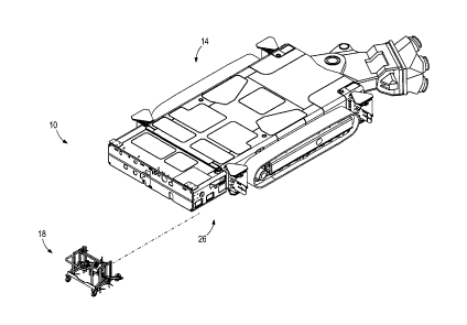
[0026] FIG. 1 shows a mining guidance system 10 including a continuous
mining machine
14, a laser emitter trolley or carriage 18, and a guide assembly 26 coupled to
the continuous
4
CA 02914558 2015-12-11
mining machine 14. The mining machine 14 engages a work face 30 of a mineral
seam 34 (FIG.
8). As shown in FIG. 2, the mining machine 14 includes a chassis or body 38, a
cutter head 42
coupled to the body 38, and a drive system 46 for moving the body 38. The body
38 defines a
roll axis 50, a pitch axis 54, and a yaw axis 58. The roll axis 50 extends
longitudinally through
the body 38. The pitch axis 54 extends transversely through the body 38, and
the yaw axis 58
extends vertically through the body 38. In the illustrated embodiment, the
drive system 46
includes a pair of tracks 82 on either side of the body 38. Other embodiments
may use wheels to
move the machine 14.
[0027] As shown in FIG. 3, the laser emitter carriage 18 includes a base
90, an adjustment
assembly 94, a first laser emitter 98, a second laser emitter 102, and a third
laser emitter 106.
The base 90 includes four wheels for moving the carriage 18 and multiple set
screws 110 for
securing the carriage 18 with respect to a mine floor. The adjustment assembly
94 includes a
gearbox 118 for pivoting each of the laser emitters 98, 102, 106 with respect
to the base 90. In
the illustrated embodiment, the first laser emitter 98 projects a first planar
laser 122. The first
planar laser 122 extends toward the seam 34 in a planar manner. The second
laser emitter 102
projects a second planar laser 126 extending toward the work face 30 of the
seam 34. The third
laser emitter 106 projects a laser beam 130 that extends toward the work face
30. The
adjustment assembly 94 permits each laser emitter 98, 102, 106 to pivot in 3
dimensions,
allowing the operator to position the planar lasers 122, 126 and the laser
beam 130 with high
precision. In one embodiment, the laser emitters 98, 102, 106 can be
accurately adjusted for
distances of up to 100 meters.
[0028] As shown in FIGS. 4-7, the guide assembly 26 includes a first target
146 (FIG. 4), a
second target 150 (FIG. 4), and a level indicator 154 (FIG. 7). Referring to
FIGS. 4 and 5, the
first target 146 is coupled to the mining machine 14 on one side of the mining
machine 14. The
first target 146 extends away from the machine 14 and includes a cross-hair
indicator 162.
Referring to FIGS. 4 and 6, the second target 150 is coupled to the mining
machine 14. The
second target 150 is aligned with the first target 146 and includes a vertical
slot 170. In the
illustrated embodiment, both targets 146, 150 are mounted on the right side of
the machine 14,
with the first target 146 being positioned proximate the cutter head and the
second target being
positioned proximate the end 166 opposite the cutter head 42. As shown in FIG.
7, the level
CA 02914558 2015-12-11
indicator 154 is positioned on the end 166 of the mining machine 14 and is
formed as a linear
marker extending across the end 166 of the machine 14. In other embodiments,
the first target
146 and second target 150 may be mounted in other positions with respect to
the machine 14,
and the targets 146, 150 and level indicator 154 may include other marker
configurations.
[0029] FIG. 8 shows the guidance system 10 in operation. The carriage 18 is
positioned
behind the mining machine 14 and the work face 30 of the seam 34. The carriage
18 is secured
in place by inserting the set screws 110 into the mine floor. The first planar
laser 122 is aligned
with the effective mean of the seam 34. The effective mean is the plane that
permits the
optimum mine yield to be extracted by the mining operation. The method for
identifying the
effective mean is known by persons of ordinary skill in the art, and is
further description of this
feature is not necessary. The second planar laser 126 is aligned with the
level indicator 154, and
the laser beam 130 is aligned to pass through the vertical slot 170 (FIG. 4)
of the second target
150 and hit the cross-hair indicator 162 (FIG. 4) on the first target 146. The
mining machine 14
is then trammed into position adjacent the work face 30 and commences
extracting material from
the work face 30.
[0030] As the mining machine 14 proceeds through the seam 34, the operator
monitors the
three laser projections 122, 126, and 130 to insure that each remains aligned
so that the machine
14 extracts the optimum yield. Maneuvering the machine 14 by a remote control,
the operator
refers to the position of the laser projections 122, 126, and 130 as guides
for adjusting the
position and orientation of the machine 14. During advance and before
commencing the
subsequent cutting sequence, the positions of the laser projections 122, 126,
and 130 are checked
and, if required, the orientation of the mining machine 14 is adjusted to
ensure accurate direction
control and positioning is maintained.
[0031] Observation of the second planar laser 126 on the level indicator
154 provides
information regarding the orientation of the mining machine 14 with respect to
the roll axis 50.
For example, if the left side of the machine 14 dips below the second planar
laser 126 as shown
in FIG. 9, the operator maneuvers the mining machine 14 to raise the left
side. This action
rotates the machine 14 in the direction 180 until the second planar laser 126
is aligned with the
level indicator 154.
6
CA 02914558 2015-12-11
[00321 Observation of the laser beam 130 on the first target 146 and the
second target 150
provides information regarding the orientation of the machine 14 with respect
to the pitch axis 54
(FIG. 2) and the yaw axis 58 (FIG. 2). If the machine 14 is out of position
the laser beam 130
will shine onto the second target 150, indicating how to correct the
orientation of the mining
machine 14. For instance, referring to FIG. 10, if the laser beam 130 is
located in the top right
corner of the second target 150, the operator steers the machine 14 to the
left. This movement
causes the second target 150 to move in the direction 184 until the laser beam
130 is aligned with
the vertical slot 170. If the laser beam 130 then shines on the first target
146 and is above the
center of the cross-hair indicator 162, the operator angles the front of the
machine 14 upward.
This action moves the first target 146 upward with respect to the laser beam
130. When the laser
beam 130 shines through the vertical slot 170 of the second target 150 and
hits the center of the
cross-hair indicator 162, the mining machine 14 is aligned and the mining
operation proceeds.
The distance of the third laser emitter 106 from the open face determines the
width of the cut.
[0033] After a cut is made, the laser emitters 98, 102, 106 are moved or
adjusted again to
provide a guide for the next phase of the mining operation. By establishing an
alignment
between the laser projections 122, 126, 130 and the guide assembly 26, the
guidance system 10
insures that mining machine 14 remains "on seam", or aligned with the
effective mean of the
mineral seam 34, even if the seam 34 is inclined at an angle.
[0034] FIGS. 11-14 illustrate another embodiment of the guidance system
410. For brevity,
only differences between the guidance system 410 and the guidance system 10
will be described
in detail. Similar parts are identified with the same reference number, plus
400.
[0035] As shown in FIG. 11, the guidance system 410 includes a first light
emitter 498 and a
second light emitter 502. The first light emitter 498 is coupled to the mining
machine 14
proximate a first or front end 40 (i.e., proximate the cutter head 42), while
the second light
emitter 502 is positioned proximate a second or rear end 44 of the machine 14.
In the illustrated
embodiment, the machine 14 includes a pair of a forward jacks 192 proximate
the front end 40
and a pair of rear jacks 194 proximate the rear end 44. The jacks 192, 194 are
extendable in a
direction parallel to the yaw axis 58 to elevate the body 38 and support the
machine 14 relative to
the mine floor or mine roof.
7
CA 02914558 2015-12-11
[0036] In the illustrated embodiment, the first light emitter 498 is
positioned forward of the
drive system 46 and is positioned adjacent a forward jack 192, while the
second light emitter 502
is positioned rearward of the drive system 46 and adjacent a rear jack 194.
Also, in the
illustrated embodiment, both the first emitter 498 and the second emitter 502
are positioned on a
right side of the body 38. In other embodiments, the emitters 498, 502 may be
positioned on
another side or may be positioned between the left and right side. In
addition, additional emitters
may be coupled to the body 38. The first light emitter 498 emits a first laser
projection 522 and
the second light emitter 502 emits a second laser projection 526.
[0037] In the illustrated embodiment, the light emitters 498, 502 are fan
lasers such that the
first projection 522 and the second projection 526 have a planar shape. In the
illustrated
embodiment, the first projection 522 and the second projection 526 and are in-
line with one
another such that the first projection 522 and the second projection 526 lie
in a common plane.
In the illustrated embodiment, the plane defined by the first and second
projections 522, 526 is
oriented parallel to the longitudinal or roll axis 50 and extends
perpendicular from the roll axis
50 toward a hanging wall or mine roof 196 (FIG. 14). Stated another way, the
first and second
projections 522, 526 may extend perpendicular to both the roll axis 50 and the
pitch axis 54
(FIG. 11). In some embodiments, the plane defined by the projections 522, 526
extends parallel
to the yaw axis 58 (FIG. 11). The plane defined by the first projection 522
and second projection
526 is generally parallel to the direction of advance of the mining machine
14.
[0038] As best shown in FIG. 14, each of the projections 522, 526 form
straight lines 532,
536, respectively on the roof 196. Depending on the size of the laser
projections 522, 526, the
lines 532, 536 may overlap and appear as a solid continuous line or as
separate line segments
spaced apart by one or more gaps.
[0039] Before the mining operation, a line 200 (FIG. 14) is drawn on the
roof 196 and is
aligned with a predetermined cutting direction or the direction of advance for
the mining
machine 14. An operator may use this line 200 or may create (e.g., with a
spray can) a second
line parallel to the line 200. In the illustrated embodiment shown in FIG. 14,
the machine 14 is
positioned such that the projections 522, 526 are aligned with the line 200 to
align the machine
with the direction of advance. During operation, the operator monitors the
position of the
8
CA 02914558 2015-12-11
projections 522, 526 relative to the line 200 to insure that the machine
maintains alignment. The
line 200 is extended a sufficient distance to insure that the machine 14 can
start and complete a
full cutting cycle.
[0040] The guidance system 410 provides a simple and straightforward system
for aligning
the machine 10 as the machine advances through a mine seam. The guidance
system 410
reduces the calibration and set-up time, therefore reducing machine downtime
between cutting
cycles.
[0041] Thus, the invention provides, among other things, a guidance system
for a mining
machine. Various features and advantages of the invention are set forth in the
following claims.
9