Note: Descriptions are shown in the official language in which they were submitted.
CA 02914570 2015-12-03
WO 2014/201225 PCT/US2014/042080
APPARATUS AND METHOD
FOR CONTROLLING LANDING GEAR
Cross-Reference to Related Application(s)
[0001] This Patent Cooperation Treaty Patent Application relies for
priority on U.S.
Provisional Patent Application Serial No. 61/835,275, entitled "APPARATUS AND
METHOD
FOR CONTROLLING LANDING GEAR," filed June 14, 2013, which is hereby
incorporated
by reference in its entirety.
Field of the Invention
[0002] The present invention concerns a construction for an apparatus for
controlling the
operation of the landing gear on an aircraft. In particular, the present
invention encompasses an
apparatus and a method for controlling the operation of the landing gear to
reduce a force
conflict associated with the operation thereof. More specifically, the present
invention
encompasses an apparatus and method of operation of a hydraulic system in an
aircraft whereby
hydraulic force conflict(s) are reduced or avoided between the hydraulic
actuator associated with
the landing gear and the hydraulic actuator associated with the landing gear
uplock device.
Description of the Related Art
[0003] As should be apparent to those skilled in the art, modern aircraft
include a
hydraulic system for operation of many of the components thereon.
[0004] One of the many systems that utilize hydraulic power for operation
is the landing
gear system. On aircraft so equipped, hydraulic pressure causes the landing
gear both to deploy
and to retract.
[0005] In addition, modern aircraft include a locking mechanism, also
referred to as an
µ`uplock," that engages the landing gear when the landing gear is in a
retracted condition. The
uplock holds the landing gear in the retracted position until the aircraft is
preparing for landing.
When the uplock is engaged, the hydraulic actuators associated with the
retraction and
deployment of the landing gear may be powered down (or depressurized), as it
is not necessary
1
CA 02914570 2015-12-03
WO 2014/201225 PCT/US2014/042080
to maintain pressure in the hydraulic system for the landing gear during
flight. The uplock
carries the weight of the landing gear while the aircraft is in flight.
[0006] When the aircraft is preparing for landing, the hydraulic system
associated with
the landing gear system is powered up and the hydraulic fluid is pressurized.
So that the landing
gear may be deployed, the hydraulic pressure acts in two primary ways that are
relevant to the
present invention. First, the hydraulic system pressurizes the actuator(s)
associated with the
landing gear, forcing the landing gear to deploy from a stowed position.
Second, the hydraulic
system pressurizes the uplock mechanism so that the uplock releases the
landing gear for
deployment.
[0007] It has been known that the simultaneous application of pressure to
the landing
gear actuator and the uplock actuator create what is referred to herein as a
"force fight" between
the landing gear actuator and the uplock. Specifically, the simultaneous
operation of the uplock
actuator and the landing gear actuator result in the application of a downward
force on the uplock
device during the time that the uplock device is releasing the landing gear.
This increases the
force on the uplock device creating the "force fight." The uplock device not
only is required to
bear the weight of the landing gear, but it is also required, for a brief
period of time, to bear the
force of the landing gear actuator as that force is applied to the landing
gear.
[0008] When the uplock device finally releases the landing gear, the
combined weight of
the landing gear and the force applied by the landing gear actuator causes a
momentary jolt of
forces on the landing gear that results in what has been termed as a "loud
thump." This loud
thump, while not detrimental to the operation of the landing gear system, may
be disconcerting
to passengers.
[0009] Numerous systems involving landing gear deployment are known in
the prior art.
Examples include, but are not limited to U.S. Patents Nos. 8,418,958,
8,109,465, and 6,792,844.
However, these prior art systems fail to adequately address deficiencies
relating to the force fight
as described above.
[0010] It is in the context of this confluence of factors that the
present invention was
developed.
2
CA 02914570 2015-12-03
WO 2014/201225 PCT/US2014/042080
Summary of the Invention
[0011] The present invention addresses, at least in part, one or more of
the deficiencies
noted with respect to the prior art.
[0012] In one aspect, the present invention provides a landing gear
system that includes
landing gear, an uplock that is releasably engageable with the landing gear,
and an uplock
hydraulic actuator operably connected to the uplock. The uplock actuator
causes the uplock to
transition between an UP condition where the uplock engages the landing gear
and a DOWN
condition where the uplock disengages from the landing gear. The landing gear
system further
includes a landing gear hydraulic actuator operably connected to the landing
gear. The landing
gear hydraulic actuator causes the landing gear to transition between an UP
condition where the
landing gear is stowed and a DOWN condition where the landing gear is
deployed. A controller
is operatively connected to the uplock hydraulic actuator and the landing gear
hydraulic actuator.
In response to receipt of a command to deploy the landing gear, the controller
actuates the
uplock hydraulic actuator and the landing gear hydraulic actuator to the UP
condition and then
actuates the uplock hydraulic actuator and the landing gear actuator to the
DOWN condition.
[0013] In one contemplated embodiment, the landing gear system also
includes hydraulic
piping connecting the uplock hydraulic actuator and the landing gear hydraulic
actuator to one
another. In this embodiment, a selector valve may be disposed in the hydraulic
piping. The
selector valve may provide selective pressurization of the hydraulic piping.
[0014] It is contemplated that the hydraulic piping connected to the
landing gear
hydraulic actuator may be larger than the hydraulic piping connected to the
uplock hydraulic
actuator.
[0015] In another embodiment, the uplock may support a weight W of the
landing gear
when the landing gear is in a stowed position, such that when the controller
actuates the landing
gear hydraulic actuator to the UP condition, the weight W supported by the
uplock is reduced.
[0016] Further, the present invention provides a landing gear system
where, when the
controller actuates the landing gear hydraulic actuator to the UP condition,
the weight W
supported by the uplock is removed.
[0017] It is contemplated that the landing gear system may encompass one
of a right side
landing gear, a left side landing gear, and a nose landing gear.
3
CA 02914570 2015-12-03
WO 2014/201225 PCT/US2014/042080
[0018] The present invention also provides a method of operating a
landing gear system
including landing gear, an uplock, wherein the uplock is releasably engageable
with the landing
gear, an uplock hydraulic actuator operably connected to the uplock, wherein
the uplock actuator
causes the uplock to transition between an UP condition where the uplock
engages the landing
gear and a DOWN condition where the uplock disengages from the landing gear, a
landing gear
hydraulic actuator operably connected to the landing gear, wherein the landing
gear hydraulic
actuator causes the landing gear to transition between an UP condition where
the landing gear is
stowed and a DOWN condition where the landing gear is deployed, and a
controller operatively
connected to the uplock hydraulic actuator and the landing gear hydraulic
actuator. The method
is contemplated that include receiving a landing gear deployment signal by the
controller, in
response to receipt of the landing gear deployment signal by the controller,
actuating the uplock
hydraulic actuator and the landing gear hydraulic actuator to the UP
condition, and subsequently
actuating the uplock hydraulic actuator and the landing gear actuator to the
DOWN condition.
[0019] Where the landing gear system also includes hydraulic piping
connecting the
uplock hydraulic actuator and the landing gear hydraulic actuator to one
another and a selector
valve disposed in the hydraulic piping adapted to provide selective
pressurization of the
hydraulic piping, the method also may include pressurizing the hydraulic
piping by the selector
valve in response to receipt by the controller of the landing gear deployment
signal before
actuating the uplock hydraulic actuator and the landing gear hydraulic
actuator.
[0020] In another contemplated embodiment, the present invention
encompasses a
landing gear system with landing gear, an uplock that is releasably engageable
with the landing
gear, and an uplock hydraulic actuator operably connected to the uplock. The
uplock actuator
causes the uplock to transition between an UP condition where the uplock
engages the landing
gear and a DOWN condition where the uplock disengages from the landing gear. A
landing gear
hydraulic actuator is operably connected to the landing gear. The landing gear
hydraulic actuator
causes the landing gear to transition between an UP condition where the
landing gear is stowed
and a DOWN condition where the landing gear is deployed. A controller is
operatively
connected to the uplock hydraulic actuator and the landing gear hydraulic
actuator. In response
to receipt of a command to deploy the landing gear, the controller actuates
the landing gear
hydraulic actuator to the UP condition and then actuates the uplock hydraulic
actuator and the
landing gear actuator to the DOWN condition.
4
CA 02914570 2015-12-03
WO 2014/201225 PCT/US2014/042080
[0021] In this embodiment, it is also contemplated that the system may
include hydraulic
piping connecting the uplock hydraulic actuator and the landing gear hydraulic
actuator to one
another. If so, a selector valve may be disposed in the hydraulic piping,
adapted to provide
selective pressurization of the hydraulic piping.
[0022] A further aspect of the present invention provides a method of
operating a landing
gear system including landing gear, an uplock, wherein the uplock is
releasably engageable with
the landing gear, an uplock hydraulic actuator operably connected to the
uplock, wherein the
uplock actuator causes the uplock to transition between an UP condition where
the uplock
engages the landing gear and a DOWN condition where the uplock disengages from
the landing
gear, a landing gear hydraulic actuator connected to the landing gear, wherein
the landing gear
hydraulic actuator causes the landing gear to transition between an UP
condition where the
landing gear is stowed and a DOWN condition where the landing gear is
deployed, and a
controller operatively connected to the uplock hydraulic actuator and the
landing gear hydraulic
actuator. The method includes receiving a landing gear deployment signal by
the controller, in
response to receipt of the landing gear deployment signal by the controller,
actuating the landing
gear hydraulic actuator to the UP condition, and actuating the uplock
hydraulic actuator and the
landing gear actuator to the DOWN condition.
[0023] With respect to this method, the present invention contemplates
the inclusion of
hydraulic piping connecting the uplock hydraulic actuator and the landing gear
hydraulic
actuator to one another and a selector valve disposed in the hydraulic piping,
adapted to provide
selective pressurization of the hydraulic piping. If so, the method also may
entail pressurizing
the hydraulic piping by the selector valve in response to receipt by the
controller of the landing
gear deployment signal before actuating the uplock hydraulic actuator and the
landing gear
hydraulic actuator.
[0024] The present invention also is considered to encompass a landing
gear system that
includes landing gear, an uplock that is releasably engageable with the
landing gear, and an
uplock hydraulic actuator operably connected to the uplock. The uplock
actuator causes the
uplock to transition between an UP condition where the uplock engages the
landing gear and a
DOWN condition where the uplock disengages from the landing gear. The system
also includes
a landing gear hydraulic actuator connected to the landing gear. The landing
gear hydraulic
actuator causes the landing gear to transition between an UP condition where
the landing gear is
CA 02914570 2015-12-03
WO 2014/201225 PCT/US2014/042080
stowed and a DOWN condition where the landing gear is deployed. The system
further includes
a piloted check valve that is operatively connected at least to the landing
gear hydraulic actuator.
A controller is operatively connected to the uplock hydraulic actuator, the
landing gear hydraulic
actuator, and the piloted check valve. In response to receipt of a command to
deploy the landing
gear, the controller causes the landing gear to be held in the UP condition
via the piloted check
valve and actuates the uplock hydraulic actuator to the DOWN condition,
resulting in a delayed
release of the piloted check valve, thereby permitting the landing gear
hydraulic actuator to
actuate to the DOWN condition.
[0025] In this embodiment, it is contemplated that the method includes
actuating the
landing gear hydraulic actuator to the UP condition before holding the landing
gear in the UP
condition via the piloted check valve.
[0026] In an additional aspect of the present invention, it is
contemplated that the landing
gear system includes hydraulic piping connecting the uplock hydraulic actuator
and the landing
gear hydraulic actuator to one another. If so, a selector valve may be
disposed in the hydraulic
piping, adapted to provide selective pressurization of the hydraulic piping.
[0027] According to another contemplated embodiment of the present
invention, a
method of operating a landing gear system that includes landing gear, an
uplock, wherein the
uplock is releasably engageable with the landing gear, an uplock hydraulic
actuator operably
connected to the uplock, wherein the uplock actuator causes the uplock to
transition between an
UP condition where the uplock engages the landing gear and a DOWN condition
where the
uplock disengages from the landing gear, a landing gear hydraulic actuator
connected to the
landing gear, wherein the landing gear hydraulic actuator causes the landing
gear to transition
between an UP condition where the landing gear is stowed and a DOWN condition
where the
landing gear is deployed, a piloted check valve operatively connected at least
to the landing gear
hydraulic actuator, and a controller operatively connected to the uplock
hydraulic actuator, the
landing gear hydraulic actuator, and the piloted check valve. The method
includes receiving a
landing gear deployment signal by the controller, in response to receipt of
the landing gear
deployment signal by the controller, holding the landing gear hydraulic
actuator in the UP
condition via the piloted check valve, actuating the uplock hydraulic actuator
to the DOWN
condition, and releasing the piloted check valve, thereby permitting the
landing gear hydraulic
actuator to actuate to the DOWN condition.
6
CA 02914570 2015-12-03
WO 2014/201225 PCT/US2014/042080
[0028] The method also may include, in response to receipt of the landing
gear
deployment signal by the controller, actuating the uplock hydraulic actuator
and the landing gear
hydraulic actuator to the UP condition.
[0029] Further, where the landing gear system further includes hydraulic
piping
connecting the uplock hydraulic actuator, the piloted check valve, and the
landing gear hydraulic
actuator to one another and a selector valve disposed in the hydraulic piping,
adapted to provide
selective pressurization of the hydraulic piping, the method also may include
pressurizing the
hydraulic piping by the selector valve in response to receipt by the
controller of the landing gear
deployment signal before actuating the uplock hydraulic actuator, the piloted
check valve, and
the landing gear hydraulic actuator.
[0030] A further aspect of the present invention contemplates a landing
gear system with
landing gear having a weight W and an uplock. The uplock is releasably
engageable with the
landing gear. The uplock supports at least a portion of the weight W of the
landing gear when
the landing gear is in a stowed position. The system also includes an uplock
hydraulic actuator
operably connected to the uplock. The uplock actuator causes the uplock to
transition between
an engaged condition and a disengaged condition, wherein in the disengaged
condition the
uplock disengages from the landing gear. The system also may include a landing
gear hydraulic
actuator connected to the landing gear. The landing gear hydraulic actuator
causes the landing
gear to transition between a stowed condition and a deployed condition. A
controller may be
operatively connected to the uplock hydraulic actuator and the landing gear
hydraulic actuator.
In response to receipt of a command to deploy the landing gear, the controller
causes actuation of
the landing gear hydraulic actuator for causing the landing gear to move into
a position that
reduces the weight W applied to the uplock, and then subsequently causes
actuation of the
uplock hydraulic actuator into the disengaged position and actuation of the
landing gear
hydraulic actuator into the deployed condition.
[0031] Further aspects of the present invention will be made apparent
from the
paragraphs that follow.
Brief Description of the Drawing(s)
[0032] The present invention will now be described in connection with the
drawings
appended hereto, in which:
7
CA 02914570 2015-12-03
WO 2014/201225 PCT/US2014/042080
[0033] Fig. 1 is a graphical representation of the mechanical system
associated with the
landing gear of an aircraft, including the uplock mechanism, the graphical
representation being
useful in describing the force fight that occurs when the landing gear is
deployed from the
stowed condition;
[0034] Fig. 2 is a graphical representation of one solution described in
the prior art for
resolving the issues associated with the force fight between the uplock
mechanism and the
landing gear on an aircraft;
[0035] Fig. 3 is a graphical representation of another solution described
in the prior art
for resolving the issues associated with the force fight between the uplock
mechanism and the
landing gear on an aircraft;
[0036] Fig. 4 is a graphical, top view of one aircraft on which one
embodiment of the
apparatus and method of the present invention may be employed;
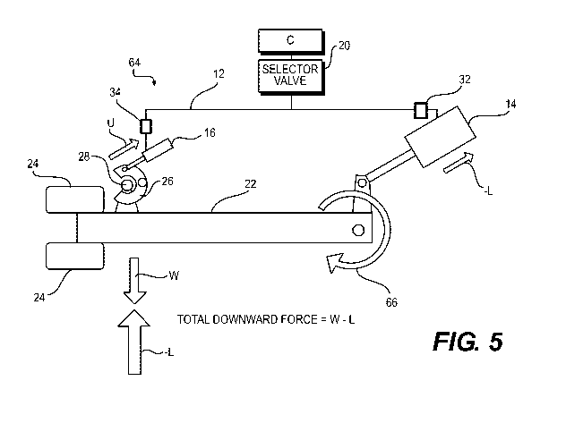
[0037] Fig. 5 is a graphical representation of a first embodiment of an
apparatus
according to the present invention;
[0038] Fig. 6 is a diagrammatic representation of the apparatus
illustrated in Fig. 5;
[0039] Fig. 7 is a flow chart illustrating a first method operable on the
apparatus
illustrated in Fig. 5;
[0040] Fig. 8 is a flow chart illustrating a second method operable on
the apparatus
illustrated in Fig. 5;
[0041] Fig. 9 is a perspective illustration of a second aircraft on which
one embodiment
of the apparatus and method of the present invention may be employed;
[0042] Fig. 10 is a graphical representation of a second embodiment of
the apparatus
according to the present invention;
[0043] Fig. 11 is a diagrammatic representation of the apparatus
illustrated in Fig. 10;
[0044] Fig. 12 is a flow chart illustrating a second method operable on
the apparatus
illustrated in Fig. 10;
[0045] Fig. 13 is a portion of a hydraulic circuit illustrating the
embodiment shown in
Fig. 10;
[0046] Fig. 14 is a graph illustrating the force fight identified with
respect to the
operation of the prior art; and
8
CA 02914570 2015-12-03
WO 2014/201225 PCT/US2014/042080
[0047] Fig. 15 is a graph illustrating the absence of the force fight
after application of at
least the second method of the present invention, as shown in Fig. 12.
Detailed Description of Embodiment(s) of the Invention
[0048] The present invention will now be described in connection with one
or more
embodiments thereof. The discussion of the embodiments is not intended to be
limiting of the
present invention. To the contrary, any discussion of embodiments is intended
to exemplify the
breadth and scope of the present invention. As should be apparent to those
skilled in the art,
variations and equivalents of the embodiment(s) described herein may be
employed without
departing from the scope of the present invention. Those variations and
equivalents are intended
to be encompassed by the scope of the present patent application.
[0049] The present invention will now be discussed in the context of the
construction of a
jet aircraft where one or more jet engines (also referred to as turbine
engines or turbofan engines)
are affixed (or attached) to the fuselage or the wings of the aircraft. While
the invention is
discussed in this context, the present invention is not intended to be limited
solely to the
construction of aircraft with jet engines. It is contemplated that the present
invention may be
employed in connection with other type of aircraft, as should be apparent to
those skilled in the
art.
[0050] With respect to the discussion that follows, it is noted that
specific directional
conventions are assumed to be known to those skilled in the art. The
directional conventions are
consistent with the forward travel direction of the aircraft. In this context,
the term "forward" (or
its equivalent) refers to the front end (or bow end) of the aircraft. The term
"rear" (or its
equivalent) refers to the aft end (back end or stern) of the aircraft. The
term "right side" (or its
equivalent) refers to the right side (or starboard side) of the aircraft as
defined by the forward and
aft ends of the aircraft. The term "left side" (or its equivalent) refers to
the left side (or port side)
of the aircraft, also as defined by the fore and aft ends thereof.
[0051] Additionally, the term "longitudinal" refers to the longitudinal
direction of the
aircraft that extends from the front end to the rear end of the aircraft. The
term "lateral" refers to
the lateral direction of the aircraft that extends from the right side to the
left side of the aircraft
(i.e., as defined by the aircraft's wingspan). As should be apparent, the
lateral direction is
9
CA 02914570 2015-12-03
WO 2014/201225 PCT/US2014/042080
orthogonal to the longitudinal direction. The terms "up" (or top) and "down"
(or bottom) refer to
a vertical direction or orientation of the aircraft when the aircraft is
parked on the ground.
[0052] Fig. 1 is graphical representation of a conventional hydraulic
system 10 for the
landing gear and uplock on an aircraft. The conventional system includes
hydraulic piping 12
that is connected to a landing gear actuator 14 and an uplock actuator 16. A
pressurization
cylinder 18 provides pressure to the hydraulic piping 12 at a suitable
pressure for the
conventional hydraulic system 10. A selector valve 20 also is provided in the
hydraulic piping.
The selector valve 20 opens to provide hydraulic pressure to the system 10
when the system 10 is
needed for operation. For example, the selector valve 20 will open to provide
hydraulic pressure
during taxi, take-off, and landing ("TTL"), which are the times when the
landing gear 22 is
deployed, among others.
[0053] As shown in Fig. 1, the landing gear 22 is in the stowed
condition. The landing
gear 22 includes two tires 24. Of course, the landing gear 22 may have a
larger or smaller
number of tires without departing from the scope of the present invention. The
uplock 26, which
is attached to the aircraft, engages a pin 28 attached to the landing gear 22.
As should be
apparent, when the system 10 is in operation, the landing gear 22 rotates, in
the direction of the
arrow 30, to transition from the stowed condition to the deployed condition.
[0054] When the system 10 is in operation, the selector valve 20 opens to
pressurize the
hydraulic piping 12. When a command is given for the landing gear 22 to be
deployed, servo
valves 32, 34 associated with the actuators 14, 16, cause fluid to fill the
actuators 14, 16 so that
the actuators 14, 16 cause the landing gear 22 to deploy. It is noted that the
servo valves 32, 34
determine if the actuators 14, 16 move in the UP direction or the DOWN
direction. In other
words, the servo valves 32, 34 are employed to determine the direction of
operation of the
associated actuators 14, 16.
[0055] It is noted that the servo valves 32, 34 are not required to
practice the present
invention. In the absence of servo valves 32, 34, the selector valve 20 may be
actuated to
pressurize the hydraulic piping so that the actuators 14, 16 move together in
the UP or DOWN
directions. In this embodiment, where the selector valve 20 provides
directionality of the
pressurization of the hydraulic piping UP or DOWN, the actuators 14, 16
respond similarly to
one another. In other words, where the selector valve 20 pressurizes the
hydraulic piping in the
UP direction, both actuators will actuate in the UP direction. When the
selector valve 20
CA 02914570 2015-12-03
WO 2014/201225 PCT/US2014/042080
pressurizes the hydraulic piping in the DOWN direction, both actuators 14, 16
will actuate in the
DOWN direction.
[0056] For purposes of the present discussion, when the landing gear
hydraulic actuator
14 moves the landing gear 22 to the stowed condition, this is referred to as
an UP condition for
the landing gear hydraulic actuator 14. When the landing gear hydraulic
actuator 14 applies
force to move the landing gear 22 to the deployed state, this is referred to
as a DOWN operation
or condition of the landing gear hydraulic actuator 14.
[0057] Also for purposes of the present discussion, when the uplock
actuator 16 rotates to
capture the pin 28 and stow the landing gear 22, this operation is referred to
an UP operation or
UP condition. When the uplock actuator 16 rotates to release the pin 28 and,
therefore, the
landing gear 22, this is referred to as a DOWN operation or condition.
[0058] In the case where the landing gear is deployed, the actuator 14
applies a
downward pressure on the landing gear 22, forcing the landing gear 22 to
rotate in the direction
of the arrow 30. The force applied by the actuator 14 is designated as "L" in
Fig. 1. At the same
time, the actuator 16 applies a force U on the uplock 26 to cause the uplock
to release the pin 28
on the landing gear. As a result of the application of the force L by the
landing gear actuator 14
and the weight W of the landing gear itself, the total downward force on the
landing gear 22 is W
+ L. As made apparent from Fig. 1, in the conventional system 10, the total
downward force (W
+ L) is experienced by the uplock 26 until the uplock 26 rotates a sufficient
degree to release the
pin 28.
[0059] The application of the weight W and the landing gear load L
simultaneously on
the uplock 26 is referred to as the "force fight" associated with the
operation of the system 10.
When the pin 28 is finally released from the uplock 26, the total downward
force (W + L)
generates a sound, often referred to as a loud "thump." While the force fight
is not detrimental to
the system 10, the loud "thump" may be distracting to passengers. At least for
this reason,
therefore, there has developed a desire to reduce the force fight.
[0060] Fig. 2 illustrates one resolution contemplated to address the
force fight. In this
first solution, a system 36 is illustrated that includes a restrictor 38. As
should be apparent to
those skilled in the art, the size of the hydraulic line to the uplock
actuator 16 is smaller than the
size of the hydraulic line to the landing gear actuator 14. While this
naturally results in a
difference in the operation of the two actuators 14, 16, this difference may
be exaggerated by the
11
CA 02914570 2015-12-03
WO 2014/201225 PCT/US2014/042080
addition of a restrictor 38. The restrictor 38 slows the flow of hydraulic
fluid to the landing gear
actuator 14 by a fractional amount of time. The slower flow causes the landing
gear actuator 14
to actuate at a point in time slightly delayed from the system 10 illustrated
in Fig. 1. As a result,
the force L applied by the landing gear actuator 14 is slightly less than that
applied in the system
10.
[0061] With respect to this first solution, it has been proposed to add a
canister to the
hydraulic piping 12 in the location of the restrictor 38. The canister is
understood to receive
some of the flow of hydraulic fluid, thereby also delaying the operation of
the landing gear
actuator 14.
[0062] Fig. 3 is a graphical illustration of a second solution to the
force fight. In this
second solution, the system 40 includes a priority valve 42 and priority
piping 44. In the system
40, the priority valve 42 prioritizes the application of hydraulic forces.
Specifically, the priority
valve 42 first allows the uplock actuator 16 to actuate, thereby releasing the
landing gear 22
before the landing gear actuator 14 is permitted to actuate. In this
embodiment, the force L
applied by the landing gear actuator 14 is delayed so that the only force
acting on the uplock 26
at the time that the uplock 26 releases the landing gear 22 is the weight W of
the landing gear 22.
[0063] Fig. 4 is a top view of one non-limiting aircraft 46 to which the
apparatus and
method of the present invention may be applied. In the embodiment shown,
aircraft 46 is a small
jet, of the type typically owned and operated privately, either by individuals
or corporations.
However, the aircraft 46 could also be a commercial aircraft operated by an
airline company.
[0064] The aircraft 46 includes a front end 48 and a rear end 50. The
fuselage 52
includes a right wing 54 and a left wing 56. Right and left engines 58, 60 are
attached to the
fuselage 52, behind the wings 54, 56. A tail section 62 (or empennage) is
attached at the rear end
50 of the aircraft 46. As should be apparent to those skilled in the art,
since aircraft 46 are
relatively modest in size in comparison to larger aircraft, the weight W of
the landing gear 22 is
similarly modest.
[0065] Given the relatively modest weight W of the landing gear 22, one
embodiment of
the present invention comprises the landing gear hydraulic system 64 as
illustrated in Fig. 5.
[0066] In the system 64, when the landing gear 22 is to be lowered from
the stowed
condition to the deployed condition, the landing gear actuator 14 is first
commanded to raise the
landing gear 22 UP. The uplock actuator 16 is similarly commanded to stroke
upwardly. As a
12
CA 02914570 2015-12-03
WO 2014/201225 PCT/US2014/042080
result of the upward stroke of the landing gear actuator 14, the landing gear
22 rotates in the
direction of the arrow 66. The upward action of the landing gear actuator 14
is contemplated to
exert a force ¨L that may be greater than the weight W of the landing gear 22.
As a result, it is
contemplated that the total downward force of the landing gear will be W ¨ L.
When L> W, it
is contemplated that the total force will be upward, against the direction of
gravity (or a negative
value).
[0067] Immediately following the upward motion of the actuators 14, 16,
the system 64
will reverse the direction of the actuators 14, 16. Since the weight W of
landing gear is
momentarily reduced or removed from the uplock 26 in this arrangement, after
application of the
upward force ¨L, when the force is reversed, the uplock 26 may be released
without any force
(W or L) thereon. As a result, there is no loud thump, as discussed in detail
above.
[0068] With continued reference to Fig. 5, it is noted that the system 64
includes a
controller C. The controller C is shown as being connected to the selector
valve 20. While this
connection is illustrated, it is noted that the controller C may be
operatively connected to any
other components of the system 64 without departing from the scope of the
present invention.
[0069] The controller C is contemplated to be a device that provides a
signal to deploy or
stow the landing gear 22. A control signal may be issued by a member of the
flight crew, for
example, to the controller C. The controller C may be part of or associated
with one or more
computer systems on board the aircraft, including, but not limited to, the
flight management
system ("FMS"). The controller C may be configured as a computing unit that
includes a
processing unit and a memory connected by a communication bus. The memory
includes data
and program instructions, such that the processing unit can process the data
and the program
instructions in order to implement the functionality of the controller
described herein. The
computing unit may also comprise a number of interfaces for receiving or
sending data elements
to external devices. For example, the controller C may include an interface
for receiving a
landing gear deployment signal and an interface for issuing a command signal
to the selector
valve 20 for causing the pressurization of the hydraulic piping.
[0070] Fig. 6 is a diagrammatic representation of the system 64
illustrated in Fig. 5. In
this view, the hydraulic pump 68 is shown. In addition, the landing gear
elements are separated
into three parts, as would be found on the aircraft 46. Specifically, the
system 64 includes a left
hand landing gear actuator 70, a right hand landing gear actuator 72, and a
nose landing gear
13
CA 02914570 2015-12-03
WO 2014/201225 PCT/US2014/042080
actuator 74. In addition, the system includes a left hand uplock actuator 76,
a right hand uplock
actuator 78, and a nose uplock actuator 80. Each of the actuators are
contemplated to operate in
the manner discussed above.
[0071] Fig. 7 is a flow diagram that illustrates a method 82 of operation
of the system 64
illustrated in Figs. 5 and 6.
[0072] The method 82 starts at 84. The method 82 proceeds to step 86,
where the system
64, at the controller C, receives a landing gear deployment signal. The
landing gear deployment
signal may be issued from the flight crew, typically by the pilot or co-pilot.
Or alternatively, the
landing gear deployment signal may be issued from a control unit that
generates the deployment
signal on a basis of one or more sensor readings, such as a reading of
altitude, for example. Upon
receipt of the landing gear deployment signal at step 86, the method 82
proceeds to step 88
where the hydraulics associated with the landing gear hydraulic system 64 are
pressurized. As
noted above, this is accomplished by the selector valve 20. It is noted,
however, that the selector
valve 20 need not be the only component that assists with the performance of
this step 88.
[0073] After the hydraulic system 64 is pressurized, the method 82
proceeds to step 90,
where both the landing gear hydraulic actuator 14 and the uplock hydraulic
actuator 16 are
directed into the UP position, at least for a brief moment in time. As
discussed in connection
with Fig. 5, the UP command provided to the landing gear hydraulic actuator 14
is contemplated
to provide a force that reduces, at least in part, the weight W of the landing
gear 22 applied to the
uplock 26. In accordance with a non-limiting example, the hydraulic actuator
14 provides a force
of ¨L that exceeds the weight W of the landing gear 22, thereby removing all
weight from the
uplock 26.
[0074] The method 82 then proceeds to step 92, where both the landing
gear hydraulic
actuator 14 and the uplock hydraulic actuator 16 are given DOWN commands and
actuate
accordingly. As noted above, the uplock hydraulic actuator 16 is smaller than
the landing gear
hydraulic actuator 14. As a result, the uplock hydraulic actuator 16 responds
more rapidly to the
DOWN command than the landing gear hydraulic actuator 14. Accordingly, the
uplock
hydraulic actuator 16 is able to move the uplock 26 into a disengaged position
before the landing
gear hydraulic actuator 14 causes a downward force to be applied by the pin 28
into engagement
with the uplock 26. Since the uplock 26 is able to be moved out of the path of
the pin 28 before
14
CA 02914570 2015-12-03
WO 2014/201225 PCT/US2014/042080
the pin 28 impacts with the uplock 26, the landing gear 22 moves without
obstruction and,
therefore, free from at least some force fight or a loud thump discussed
above.
[0075] The method 82 ends at 94.
[0076] Fig. 8 is a flow diagram that illustrates a second method 96 of
operation of the
system 64 illustrated in Figs. 5 and 6, in which the landing gear hydraulic
actuator 14 is provided
with an UP command independently of the uplock hydraulic actuator.
[0077] This second method 96 starts at 98.
[0078] At step 100, the hydraulic system 64 receives a landing gear
deployment signal at
the controller C.
[0079] At step 102, the hydraulics associated with the system 64 are
pressurized. As
noted above, the selector valve 20 is contemplated to accomplish this
function. As noted, the
selector valve 20 may operate independently or together with other components
to pressurize the
hydraulic system 64.
[0080] At step 104, the landing gear hydraulic actuator 14 is commanded
into the UP
mode of operation. As with the method 82, performance of this step 104 lifts
the weight W of
the landing gear 22 from the uplock 26. As before, it is contemplated that the
operation of the
landing gear hydraulic actuator 14 will apply a load ¨L onto the landing gear
22. Thereby
reducing the load on the uplock 26. In a non-limiting embodiment, L > W, such
that the landing
gear 22 is contemplated to move upwardly within the uplock 26.
[0081] The method 96 then proceeds to step 106 where the uplock hydraulic
actuator 16
is commanded DOWN, thereby releasing the pin 28 on the landing gear 22. Since
the landing
gear 22 has been raised by the landing gear hydraulic actuator UP command,
there is reduced
weight W on the uplock at this step 106. Accordingly, there is reduced force
fight or loud
thump.
[0082] The method 96 ends at step 110.
[0083] Fig. 9 illustrates a different type of jet aircraft 112. This
aircraft 112 is larger than
the aircraft 46 illustrated in Fig. 4. Specifically, this aircraft 112 is
contemplated to be of a size
suitable for commercial service. However, it is to be understood that it also
may be used for
private purposes, either by individuals or corporations
CA 02914570 2015-12-03
WO 2014/201225 PCT/US2014/042080
[0084] The aircraft 112 has a fuselage 114 with a front end 116 and a
rear end 118. Two
wings 120, 122 extend laterally from the fuselage 114. Engines 124, 126 are
mounted on the
wings 120. A tail section 128 is mounted to the rear end 118 of the fuselage
114.
[0085] The system 64 and methods 82, 96 that are discussed above for the
aircraft 46 are
contemplated to be applicable to the aircraft 112 that is illustrated in Fig.
9.
[0086] In addition, other apparatuses and methods are contemplated in
connection with
the aircraft 112, primarily because the aircraft is larger. Larger aircraft
112 are heavier. As a
result, the landing gear for larger aircraft may be more robust. This means
that the landing gear
for a larger aircraft, such as the aircraft 112, will be heavier than the
landing gear 22 for the
aircraft 46. Heavier landing gear 22 are contemplated to present additional
engineering
challenges.
[0087] In particular, it is contemplated that, when the landing gear for
an aircraft 46, 112
exceed a predetermined weight W, it may not be suitable for the hydraulic pump
68 to provide
sufficient pressure to direct the landing gear hydraulic actuator 14 UP over a
brief period of time.
It is possible that, if the hydraulic pump 68 attempts to lift the landing
gear 22 rapidly, cavitation
may occur in the hydraulic pump 68. Cavitation occurs when a fluid is subject
to pressures such
that the fluid flashes into vapor. When the vapor returns to a liquid state,
the collapse of the
vapor "bubbles" may have deleterious effects on the operation of the hydraulic
pump 68.
Accordingly, when the weight W of the landing gear exceeds a predetermined
amount, it may be
more prudent to employ the apparatus illustrated in Fig. 10 and the method
discussed in
connection with Fig. 11.
[0088] Fig. 10 is a graphical representation of one hydraulic system 130
that may be
employed on the aircraft 112. The hydraulic system 130 is similar to the
hydraulic systems
described above. The hydraulic system 130 differs in that the system 130
includes a piloted
check valve 132 (also referred to as a pilot operated check valve 132)
upstream of the landing
gear hydraulic actuator 14. The piloted check valve 132 delays the actuation
of the landing gear
hydraulic actuator 14 by a time sufficient for the uplock to clear the pin 28.
As a result, the
addition of the piloted check valve 132 helps to avoid the force fight or loud
thump described
above.
[0089] As should be apparent to those skilled in the art, a check valve
typically operates
to permit fluid flow in one direction only. The check valve then closes when
the pressure falls
16
CA 02914570 2015-12-03
WO 2014/201225 PCT/US2014/042080
below the predetermined threshold. As should be apparent to those skilled in
the art, a piloted
check valve 132 operates similarly to a non-piloted check valve. A piloted
check valve 132 may
be actuated during the time when a pilot pressure is maintained in the piloted
check valve 132.
In other words, for a piloted check valve 132 to operate, the piloted check
valve 132 must be
subjected to a predetermined piloted pressure. During the time that the
piloted check valve 132
is subjected to the predetermined piloted pressure, the piloted check valve
132 will permit the
hydraulic fluid to flow in a direction opposite to that of a non-piloted check
valve. As should be
apparent, the predetermined piloted pressure may not be the same as the
pressure that triggers the
opening of the check valve.
[0090] With this overview, the operation of the system 130 will now be
explained.
Specifically, when the selector valve 20 is opened (i.e., in the UP position),
the hydraulic piping
12 is pressurized. When the hydraulic piping 12 is pressurized (i.e., in the
UP direction), the
landing gear actuator 14 also is pressurized (i.e., in the UP position). The
selector valve 20 then
transitions from the UP position to a DOWN position. During this transition,
the pressure in the
landing gear actuator 14 is maintained in the UP position by the piloted check
valve 132. As a
result of the upward stroke of the landing gear actuator 14, the landing gear
rotates in the
direction of the arrow 66. The landing gear actuator 14 is held in the UP
position by the piloted
check valve 132 during the time that the selector valve 20 transitions between
the UP position
and the DOWN position. After the selector valve 20 transitions to the DOWN
position, the
hydraulic piping 12 is pressurized in the DOWN position. This causes the
uplock actuator 16
and the pilot line of the piloted check valve 132 to become pressurized in the
DOWN condition
and also permits the landing gear actuator 14 to actuate into the DOWN
position. The piloted
check valve 132 releases the landing gear hydraulic actuator 14 from the UP
condition after a
brief delay, which permits the uplock 26 to move first, thereby avoiding
interference with the pin
28 and, therefore, the landing gear 22.
[0091] Like Fig. 6, Fig. 11 is a diagrammatic illustration of the system
130 illustrated in
Fig. 10. In this view, the hydraulic pump 68 is shown. In addition, the
landing gear elements are
separated into three parts, as would be found on the aircraft 112.
Specifically, the system 130
includes a left hand landing gear actuator 70, a right hand landing gear
actuator 72, and a nose
landing gear actuator 74. In addition, the system includes a left hand uplock
actuator 76, a right
17
CA 02914570 2015-12-03
WO 2014/201225 PCT/US2014/042080
hand uplock actuator 78, and a nose uplock actuator 80. Each of the actuators
are contemplated
to operate in the manner discussed above.
[0092] Fig. 12 is a flow chart that illustrates one method 134
contemplated for operation
of the system 130 illustrated in Figs. 9 and 10.
[0093] The method 134 begins at step 136.
[0094] The method 134 proceeds to step 138 where the system 130 receives
a landing
gear deployment signal at the controller C.
[0095] The method 134 proceeds to step 140 where the system 130 is
pressurized with
hydraulic fluid. As noted above, this is accomplished by the selector valve
20.
[0096] From step 140, the method 134 proceeds to step 142, where the
landing gear
hydraulic actuator 16 is actuated UP.
[0097] At step 144, the pressure retained by the piloted check valve 132
is released. In
this step, the piloted check valve 132 opens so that the hydraulic fluid may
actuate the landing
gear actuator 14 in the DOWN direction, which causes the landing gear 22 to
deploy from the
stowed condition.
[0098] At step 146, the landing gear hydraulic actuator 14 is actuated
DOWN to lower
the landing gear 22 into the deployed condition.
[0099] The method 134 ends at step 148.
[00100] Fig. 13 is a schematic diagram of a portion of the system 130
illustrated in Figs.
10-11. In the illustrated embodiment, the selector valve 20 is shown. In
addition, a free fall
selector valve 150 is illustrated together with a check valve 152 and the
piloted check valve 132.
As should be apparent to those skilled in the art, the selector valve 150
directs hydraulic fluid
into the system 130 to make operation of the various hydraulic components
possible. The
selector valve 150 may be actuated via any of a number of different
methodologies including, but
not limited to, electrical activation (e.g., by the controller C), manual
activation,
electromechanical activation, etc. The free fall selector valve 150 is
actuated (typically
manually) by a member of the flight crew when the aircraft is in an emergency
mode of
operation and it becomes necessary to deploy the landing gear manually. The
free fall selector
valve 150 may release the pressure in the hydraulic system 130 to permit
manual deployment of
the landing gear 22. The check valve 152, which is a non-piloted check valve,
is understood to
18
CA 02914570 2015-12-03
WO 2014/201225 PCT/US2014/042080
facilitate operation of the system 130 when, for example, the free fall
selector valve 150 is
actuated.
[00101] Fig. 14 is a graphical representation of a prior art hydraulic
system that includes
the force fight 154 discussed above. The spike in forces, resulting from the
combined weight W
and load L from the landing gear hydraulic actuator 14, is visible in this
view.
[00102] Fig. 15 is a graphical representation of the operation of the
system 130 of the
present invention, which is considered representative of the various
embodiments of the present
invention. The force fight is absent 156 from this view.
[00103] As noted above, the embodiment(s) described herein are intended to
be exemplary
of the wide breadth of the present invention. Variations and equivalents of
the described
embodiment(s) are intended to be encompassed by the present invention, as if
described herein.
19