Note: Descriptions are shown in the official language in which they were submitted.
CA 02914930 2015-12-09
WO 2014/201072 PCT/US2014/041821
1
A NONLINEAR LINE OF WEAKNESS FORMED BY A PERFORATING APPARATUS
FIELD OF THE INVENTION
The present disclosure relates to nonlinear lines of weakness for rolled
products, and
more specifically, relates to a web comprising a nonlinear line of weakness
comprising one or
more perforations and one or more bond areas.
BACKGROUND
Many articles and packages include or can include a strip of material that has
a line of
weakness having one or more perforations to aid in tearing the article or
package. For example,
articles can include wax paper, aluminum foil, disposable bags, and sanitary
tissue products, such
as toilet tissue, facial tissue, and paper towels manufactured in the form of
a web. Sanitary tissue
products include lines of weakness to permit tearing off discrete sheets, for
example, as is well
known in the art. Such products are commonly used in households, businesses,
restaurants,
shops, and the like.
Typically, a line of weakness consists of a straight perforation across the
width of the
web. Creating perforations at high speeds and long widths is very challenging.
Small vibrations
in the equipment can result in non-perforated areas and/or inconsistent
quality in the perforation
and/or additional wear on the equipment. Further, tight tolerances between
equipment must be
maintained. Generally, there are three ways to perforate webs: die cutting,
laser cutting, and flex
blade cutting. Die cutting is a compression or crush cut in which a knife
contacts a hardened
anvil roll or a male roll interacts with a female roll to create one or more
perforations. Die
cutting usually is associated with high replacement costs and low speeds.
Further die cutting
does not allow for accuracy at long widths or mismatched speed operation.
Similarly, laser
cutting is a high-powered method to perforate webs. Laser cutting is usually
used on thicker
substrates and on cuts requiring a high degree of accuracy. Still further,
flex blade cutting is a cut
created by shearing the web. Flex blade cutting requires at least one blade to
flex against a
relatively stationary blade or anvil during operation to cut the web. Relative
to the above cutting
methods, flex blade cutting is generally lower cost, can be performed at
higher speeds, and can be
run at mismatched speeds. In addition to the above, water jet, steam, and
spark aperture cutting
methods can also be used to create lines of weakness. These methods have been
found to be
incompatible with the product being manufactured and/or inadequate for high
speed, low cost
production of perforated webs.
CA 02914930 2015-12-09
WO 2014/201072 PCT/US2014/041821
2
For example, using two rotating rolls to create a shaped line of weakness can
be complex
and expensive. The two rotating rolls must be matched to come together at
exactly the right
moment in time. Stated another way, the male roll must be synchronized with
the female roll.
Further, creating perforations with a rotating male roll and a rotating female
roll can require a
greater force be imparted to the web to create the line of weakness. Finally,
the equipment to
create such a line of weakness is large and must operate at lower speeds to
maintain proper
matching of the rolls.
It has been found that consumers desire products that are usable and have a
distinguishing
feature over other products. Manufacturers of various products, for example
sanitary tissue
products, desire that consumers of such products be able to readily
distinguish their products
from similar products produced by competitors. One way a manufacturer can
distinguish its
products from other products is to impart physical characteristics into the
web that differ from
other manufacturers' products. A shaped perforation is one distinguishing
characteristic that can
be added to the product. The shape of the line of weakness would not only
provide a way for
consumers to distinguish a manufacture's product, but also communicate to
consumers a
perception of luxury, elegance, and softness and/or strength.
Further, manufactures desire a shaped perforation that consumers of such
products can
easily and readily interact with. Often a straight perforation on a sanitary
tissue product, for
example, can rest directly on the adjacent layer making it difficult to see
the end of the sheet. ,
This can make it difficult for a user to locate, grasp, and/or dispense the
product. A straight
perforation can allow for only a single plane of the product on which a user
can grasp for
dispensing.
However, producing a web with a shaped perforation adds more complexity to the
manufacturing process. As previously stated, tight tolerances and minimal to
no vibration are
required in manufacturing a line of weakness at the high speeds necessary for
commercial
viability. Thus, adding a shape to the anvil and/or the blade can increase the
risk of introducing
processing complexities and complications into commercial manufacturing
operations for a
perforated web.
Still further, as previously stated, consumers desire a product that they can
easily and
readily interact with. A shaped perforation adds a degree of complexity to the
processing
capability of manufactures to provide a product that tears at least as well as
a currently marketed
product having a straight line of weakness. Further, imparting a shaped line
of weakness in the
product can lead to unequal perforations and/or inconsistency in tearing.
CA 02914930 2015-12-09
WO 2014/201072 PCT/US2014/041821
3
Accordingly, there is a continuing unmet need for an improved perforating
apparatus to
manufacture a web with a shaped line of weakness.
Accordingly, there is a continuing unmet need for an improved method to
manufacture a
web with a shaped line of weakness.
Still further, there is a continuing unmet need for a sanitary tissue product
having
individual sheets separated by shaped lines of weakness, and which allows
consumers to easily
and readily interact with the product. More specifically, there is a
continuing unmet need for a
sanitary tissue product that allows the consumer to grasp the first, exposed
sheet of the product
readily and easily for dispensing and use.
SUMMARY
In one example embodiment, a web can comprise a curvilinear line of weakness.
The
curvilinear line of weakness can comprise a plurality of perforations. Each of
the plurality of
perforations can be separated by a bond area. Further, each of the plurality
of perforations can
have a perforation length and each bond area can have a non-perforation
length, and at least two
of the perforations lengths can be substantially equal.
In another example embodiment, a web can comprise a curvilinear line of
weakness. The
curvilinear line of weakness can comprise a plurality of perforations. Each of
the plurality of
perforations can be separated by a bond area. Each of the plurality of
perforations can have a
perforation length and each bond area can have a non-perforation length, and
at least two of the
non-perforations lengths can be substantially equal.
In yet another example embodiment, a web can comprise a curvilinear line of
weakness.
The curvilinear line of weakness can comprise a plurality of perforations.
Each of the plurality
of perforations can be separated by a bond area. Each of the plurality of
perforations can have a
perforation length and each bond area can have a non-perforation length, and
at least two of the
non-perforations lengths can be substantially unequal and at least two of the
perforation lengths
can be substantially unequal.
BRIEF DESCRIPTION OF THE DRAWINGS
The above-mentioned and other features and advantages of this disclosure, and
the
manner of attaining them, will become more apparent and the disclosure itself
will be better
understood by reference to the following description of non-limiting
embodiments of the
disclosure taken in conjunction with the accompanying drawings, wherein:
CA 02914930 2015-12-09
WO 2014/201072 PCT/US2014/041821
4
Fig. 1 is a perspective view of a perforating apparatus in accordance with one
non-
limiting embodiment of the present disclosure;
Fig. 2 is a partial side elevation view of a perforating apparatus in
accordance with one
non-limiting embodiment of the present disclosure;
Fig. 3 is a partial side elevation view of a perforating apparatus in
accordance with one
non-limiting embodiment of the present disclosure;
Fig. 4 is a partial side elevation view of a perforating apparatus in
accordance with one
non-limiting embodiment of the present disclosure;
Fig. 4A is a side elevation view of an anvil disposed on a cylinder in
accordance with one
non-limiting embodiment of the present disclosure;
Fig. 5 is a front elevation view of an anvil disposed on a cylinder in
accordance with one
non-limiting embodiment of the present disclosure;
Fig. 5A is a side elevation view of an anvil disposed on a cylinder in
accordance with one
non-limiting embodiment of the present disclosure;
Figs. 5B-G are a cross sectional view of Section 5B-G of Fig. 5;
Fig. 6 is a front elevation view of an anvil disposed on cylinder in
accordance with one
non-limiting embodiment of the present disclosure;
Fig. 7 is a front elevation view of an anvil disposed on cylinder in
accordance with one
non-limiting embodiment of the present disclosure;
Fig. 8 is a plan view of a web in position to be perforated by a perforating
apparatus in
accordance with one non-limiting embodiment of the present disclosure;
Fig. 9 is a plan view of a web in position to be perforated by a perforating
apparatus in
accordance with one non-limiting embodiment of the present disclosure;
Figs. 10-10R are schematic representations showing the progression of a web
being
perforated in accordance with one non-limiting embodiment of the present
disclosure;
Fig. 11 is a perspective view of a perforating apparatus in accordance with
one non-
limiting embodiment of the present disclosure;
Fig. 12 is a schematic representation of a notched anvil in accordance with
one non-
limiting embodiment of the present disclosure;
Fig. 13 is a perspective view of a perforating apparatus in accordance with
one non-
limiting embodiment of the present disclosure;
Fig. 14 is a partial side elevation view of a perforating apparatus in
accordance with one
non-limiting embodiment of the present disclosure;
CA 02914930 2015-12-09
WO 2014/201072 PCT/US2014/041821
Fig. 15 is a partial side elevation view of a perforating apparatus in
accordance with one
non-limiting embodiment of the present disclosure;
Fig. 16 is a front elevation view of a blade disposed on a support in
accordance with one
non-limiting embodiment of the present disclosure;
5 Fig. 17 is a cross sectional view of Section 17-17 of Fig. 16;
Fig. 18 is a perspective schematic representation of a perforating apparatus
in accordance
with one non-limiting embodiment of the present disclosure;
Fig. 19 is a schematic representation of a notched blade disposed on a support
and a
shaped anvil disposed in a cylinder in accordance with one non-limiting
embodiment of the
present disclosure;
Fig. 20 is a schematic representation of a portion of an anvil indicating
perforating length
or non-perforating length to determine the tooth length or recessed portion
length in accordance
with one non-limiting embodiment of the present disclosure;
Fig. 21 is a schematic representation of a notched blade disposed on a support
and a
shaped anvil disposed in a cylinder in accordance with one non-limiting
embodiment of the
present disclosure;
Fig. 22 is a perspective view of a web in accordance with one non-limiting
embodiment
of the present disclosure; and
Figs. 23A-Q are schematic representations of the shape of a line of weakness
in
accordance with one non-limiting embodiment of the present disclosure.
DETAILED DESCRIPTION
Various non-limiting embodiments of the present disclosure will now be
described to
provide an overall understanding of the principles of the structure, function,
manufacture, and use
of a web comprising a shaped line of weakness. The features illustrated or
described in
connection with one non-limiting embodiment can be combined with the features
of other non-
limiting embodiments. Such modifications and variations are intended to be
included within the
scope of this disclosure.
"Fibrous structure" as used herein means a structure that comprises one or
more fibrous
elements. In one example, a fibrous structure according to the present
disclosure means an
association of fibrous elements that together form a structure capable of
performing a function.
A nonlimiting example of a fibrous structure of the present disclosure is an
absorbent paper
product, which can be a sanitary tissue product such as a paper towel, bath
tissue, or other rolled,
absorbent paper product.
CA 02914930 2015-12-09
WO 2014/201072 PCT/US2014/041821
6
Non-limiting examples of processes for making fibrous structures include known
wet-laid
papermaking processes, air-laid papermaking processes, and wet, solution, and
dry filament
spinning processes, for example meltblowing and spunbonding spinning
processes, that are
typically referred to as nonwoven processes. Such processes can comprise the
steps of preparing
a fiber composition in the form of a suspension in a medium, either wet, more
specifically
aqueous medium, or dry, more specifically gaseous, i.e. with air as medium.
The aqueous
medium used for wet-laid processes is oftentimes referred to as fiber slurry.
The fibrous
suspension is then used to deposit a plurality of fibers onto a forming wire
or belt such that an
embryonic fibrous structure is formed, after which drying and/or bonding the
fibers together
results in a fibrous structure. Further processing the fibrous structure can
be carried out such that
a finished fibrous structure is formed. For example, in typical papermaking
processes, the
finished fibrous structure is the ,fibrous structure that is wound on the reel
at the end of
papermaking and can subsequently be converted into a finished product (e.g., a
sanitary tissue
product).
"Fibrous element" as used herein means an elongate particulate having a length
greatly
exceeding its average diameter, i.e. a length to average diameter ratio of at
least about 10. A
fibrous element may be a filament or a fiber. In one example, the fibrous
element is a single
fibrous element rather than a yarn comprising a plurality of fibrous elements.
The fibrous elements of the present disclosure may be spun from polymer melt
compositions via suitable spinning operations, such as meltblowing and/or
spunbonding and/or
they may be obtained from natural sources such as vegetative sources, for
example trees.
The fibrous elements of the present disclosure may be monocomponent and/or
multicomponent. For example, the fibrous elements may comprise bicomponent
fibers and/or
filaments. The bicomponent fibers and/or filaments may be in any form, such as
side-by-side,
core and sheath, islands-in-the-sea and the like.
"Filament" as used herein means an elongate particulate as described above
that exhibits
a length of greater than or equal to 5.08 cm (2 in.) and/or greater than or
equal to 7.62 cm (3 in.)
and/or greater than or equal to 10.16 cm (4 in.) and/or greater than or equal
to 15.24 cm (6 in.).
Filaments are typically considered continuous or substantially continuous in
nature.
Filaments are relatively longer than fibers. Non-limiting examples of
filaments include
meltblown and/or spunbond filaments. Non-limiting examples of polymers that
can be spun into
filaments include natural polymers, such as starch, starch derivatives,
cellulose, such as rayon
and/or lyocell, and cellulose derivatives, hemicellulose, hemicellulose
derivatives, and synthetic
polymers including, but not limited to polyvinyl alcohol, thermoplastic
polymer, such as
CA 02914930 2015-12-09
WO 2014/201072 PCT/US2014/041821
7
polyesters, nylons, polyolefins such as polypropylene filaments, polyethylene
filaments, and
biodegradable thermoplastic fibers such as polylactic acid filaments,
polyhydroxyalkanoate
filaments, polyesteramide filaments and polycaprolactone filaments.
"Fiber" as used herein means an elongate particulate as described above that
exhibits a
length of less than 5.08 cm (2 in.) and/or less than 3.81 cm (1.5 in.) and/or
less than 2.54 cm (1
in.). A fiber can be elongate physical structure having an apparent length
greatly exceeding its
apparent diameter (i.e., a length to diameter ratio of at least about 10.)
Fibers having a non-
circular cross-section and/or tubular shape are common; the "diameter" in this
case can be
considered to be the diameter of a circle having a cross-sectional area equal
to the cross-sectional
area of the fiber.
Fibers are typically considered discontinuous in nature. Non-limiting examples
of fibers
include pulp fibers, such as wood pulp fibers, and synthetic staple fibers
such as polypropylene,
polyethylene, polyester, copolymers thereof, rayon, glass fibers and polyvinyl
alcohol fibers.
Staple fibers may be produced by spinning a filament tow and then cutting the
tow into
segments of less than 5.08 cm (2 in.) thus producing fibers.
In one example of the present disclosure, a fiber may be a naturally occurring
fiber, which
means it is obtained from a naturally occurring source, such as a vegetative
source, for example a
tree and/or other plant. Such fibers are typically used in papermaking and are
oftentimes referred
to as papermaking fibers. Papermaking fibers useful in the present disclosure
include cellulosic
fibers commonly known as wood pulp fibers. Applicable wood pulps include
chemical pulps,
such as Kraft, sulfite, and sulfate pulps, as well as mechanical pulps
including, for example,
groundwood, thermomechanical pulp and chemically modified thermomechanical
pulp.
Chemical pulps, however, may be preferred since they impart a superior tactile
sense of softness
to fibrous structures made therefrom. Pulps derived from both deciduous trees
(hereinafter, also
referred to as "hardwood") and coniferous trees (hereinafter, also referred to
as "softwood") may
be utilized. The hardwood and softwood fibers can be blended, or
alternatively, can be deposited
in layers to provide a stratified web. Also applicable to the present
disclosure are fibers derived
from recycled paper, which may contain any or all of the above categories of
fibers as well as
other non-fibrous polymers such as fillers, softening agents, wet and dry
strength agents, and
adhesives used to facilitate the original papermaking.
In addition to the various wood pulp fibers, other cellulosic fibers such as
cotton linters,
rayon, lyocell, and bagasse fibers can be used in the fibrous structures of
the present disclosure.
"Sanitary tissue product" as used herein means one or more finished fibrous
structures,
that is useful as a wiping implement for post-urinary and post-bowel movement
cleaning (e.g.,
CA 02914930 2015-12-09
WO 2014/201072 PCT/US2014/041821
8
toilet tissue, also referred to as bath tissue, and wet wipes), for
otorhinolaryngological discharges
(e.g., facial tissue), and multi-functional absorbent and cleaning and drying
uses (e.g., paper
towels, shop towels). The sanitary tissue products can be embossed or not
embossed and creped
or uncreped.
In one example, sanitary tissue products rolled about a fibrous core of the
present
disclosure can have a basis weight between about 10 g/m2 to about 160 g/m2 or
from about 20
g/m2 to about 150 g/m2 or from about 35 g/m2 to about 120 g/m2 or from about
55 to 100 g/m2,
specifically reciting all 0.1 g/m2 increments within the recited ranges. In
addition, the sanitary
tissue products can have a basis weight between about 40 g/m2 to about 140
g/m2 and/or from
about 50 g/m2 to about 120 g/m2 and/or from about 55 g/m2 to about 105 g/m2
and/or from about
60 to 100 g/m2, specifically reciting all 0.1 g/m2 increments within the
recited ranges. Other
basis weights for other materials, such as wrapping paper and aluminum foil,
are also within the
scope of the present disclosure.
"Basis Weight" as used herein is the weight per unit area of a sample reported
in lbs/3000
ft2 or g/m 2. Basis weight can be measured by preparing one or more samples to
create a total
area (i.e., flat, in the material's non-cylindrical form) of at least 100 in2
(accurate to +/- 0.1 in2)
and weighing the sample(s) on a top loading calibrated balance with a
resolution of 0.001 g or
smaller. The balance is protected from air drafts and other disturbances using
a draft shield.
Weights are recorded when the readings on the balance become constant. The
total weight (lbs
or g) is calculated and the total area of the samples (ft2 or m2) is measured.
The basis weight in
units of lbs/3,000 ft2 is calculated by dividing the total weight (lbs) by the
total area of the
samples (ft2) and multiplying by 3000. The basis weight in units of g/m2 is
calculated by
dividing the total weight (g) by the total area of the samples (m2).
"Density" as used hereing is calculated as the quotient of the Basis Weight
expressed in
grams per square meter divided by the Caliper expressed in microns. The
resulting Density is
expressed as grams per cubic centimeter (g/cm3 or g/cc). Sanitary tissue
products of the persent
disclosure can have a density of greater than about 0.05 g/cm3 and/or greater
than 0.06 g/cm3
and/or greater than 0.07 g/cm3 and/or less than 0.10 g/cm3 and/or less than
0.09 g/cm3 and/or less
than 0.08 g/cm3 and/or less than 0.60 g/cm3 and/or less than 0.30 g/cm3 and/or
less than 0.20
g/cm3 and/or less than 0.15 g/cm3 and/or less than 0.10 g/cm3 and/or less than
0.07 g/cm3 and/or
less than 0.05 g/cm3 and/or from about 0.01 g/cm3 to about 0.20 g/cm3 and/or
from about 0.02
g/cm3 to about 0.15 g/cm3 and/or from about 0.02 g/cm3 to about 0.10 g/cm3.
"Ply" as used herein means an individual, integral fibrous structure.
CA 02914930 2015-12-09
WO 2014/201072 PCT/US2014/041821
9
"Plies" as used herein means two or more individual, integral fibrous
structures disposed
in a substantially contiguous, face-to-face relationship with one another,
forming a multi-ply
fibrous structure and/or multi-ply sanitary tissue product. It is also
contemplated that an
individual, integral fibrous structure can effectively form a multi-ply
fibrous structure, for
example, by being folded on itself.
"Rolled product(s)" as used herein include plastics, fibrous structures,
paper, sanitary
tissue products, paperboard, polymeric materials, aluminum foils, and/or films
that are in the
form of a web and can be wound about a core. For example, the sanitary tissue
product can be
convolutedly wound upon itself about a core or without a core to form a
sanitary tissue product
roll or can be in the form of discrete sheets, as is commonly known for toilet
tissue and paper
towels.
"Machine Direction," MD, as used herein is the direction of manufacture for a
perforated
web. The machine direction can be the direction in which a web is fed through
a perforating
apparatus that can comprise a rotating cylinder and support, as discussed
below in one
embodiment. The machine direction can be the direction in which web travels as
it passes
through a blade and an anvil of a perforating apparatus.
"Cross Machine Direction," CD as used herein is the direction substantially
perpendicular
to the machine direction. The cross machine direction can be substantially
perpendicular to the
direction in which a web is fed through a cylinder and lower support in one
embodiment. The
cross machine direction can be the direction substantially perpendicular to
the direction in which
web travels as it passes through a blade and an anvil.
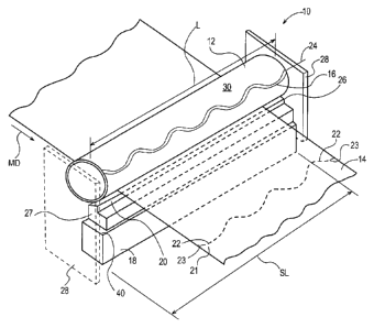
Referring to Fig. 1, a perforating apparatus 10 is shown for forming a shaped
line of
weakness 21 comprising one or more perforations 22 on a web 14. The
perforating apparatus 10
comprises a cylinder 12 and a support 18. The cylinder 12 can be suspended
between one or
more braces 28 that serve to hold cylinder 12 in operative position. The
cylinder 12 has a
longitudinal cylinder axis 24 about which the cylinder 12 is rotatable. The
cylinder 12 can have a
substantially circular shaped cross-section or oval-like shaped cross-section
or any other shaped
cross-section that can rotate about an axis and operatively engage a support
18. The cylinder 12
can comprise an outer surface 30 positioned radially outward from and
substantially surrounding
the longitudinal cylinder axis 24.
The cylinder 12 can comprise an anvil. In one example embodiment, the anvil 12
can be
disposed on the outer surface 30 of the cylinder 12. In another example
embodiment, the anvil
16 can be disposed on an anvil insert 29 that can be removably attached to the
cylinder 12. The
anvil insert 29 can be magnetically attached to the outer surface 30 of the
cylinder 12. In another
CA 02914930 2015-12-09
WO 2014/201072 PCT/US2014/041821
embodiment, the anvil insert 29 can be chemically attached, such as by glue,
or mechanically
attached, such as by clamping, bolting, or otherwise joining to the outer
surface 30 of the
cylinder 12. Opposite the cylinder 12, the support 18 can comprise a blade 20.
The blade 20 can
be disposed on the support 18. By "disposed" is meant the blade can be
attached, removeably
5 attached, clamped, bolted, or otherwise held by the support 18 in a
stable operative position with
respect to the cylinder 12.
In another example embodiment, the support 18 can comprise a blade holder 27.
The
blade 20 can be disposed on the blade holder 27 in such a manner as to
maintain sufficient
stability when in contacting engagement with the anvil 16. Further, a clamp
31, shown in Fig. 2,
10 can be disposed on the blade holder 27 and partially surround the blade
20. The clamp 31 can be
designed generally as indicated in Fig. 2 with the blade being held between
two parts of the
clamp that can each flex relative to the other. In this manner the clamp 31
can removably hold
the blade 20 such that the blade 20 can deflect when it contacts the anvil 16.
This deflection and
the inherent flexibility of the blade 20 allows for improved perforation
reliability by being more
forgiving to slight differences in machine tolerances. Thus, the support 18
serves to hold the
blade holder 27, which can include a clamp 31, and thus the blade 20, in a
relatively stable
orientation during operation.
The cylinder 12 is moveable such that the cylinder 12 can operatively engage
with the
support 18. Operative engagement means the support 18 can be arranged in
relationship to the
cylinder 12 such that the blade 20 can make contact with the anvil 16 as it
rotates past the blade
20; the contact sufficient to make one or more perforations 22 in a web 14. In
one embodiment,
the contact between the anvil 16 and the blade 20 is a shearing action. Thus,
in one embodiment,
the perforating apparatus can be a shear-cutting device. The blade 20 can be
disposed on the
support 18 so as to cooperate in contacting relationship with the anvil 20
disposed on the cylinder
12 to impart a line of weakness 21 comprising one or more perforations 22 and
one or more bond
areas 23 in the web 14. The bond areas 23 are the portion of the web between
two adjacent
perforations. The inventors found a unique and surprising result from shaping
the element
disposed on the rotating cylinder 12. In one embodiment, the shaped element
can comprise the
anvil 16. The resulting perforation on the sheet takes on the same or a
similar shape as the
shaped rotating element, which, in one embodiment is a shaped anvil 16. The
same result does
not occur if the shape is not on the rotating roll.
As previously stated, the line of weakness 21 comprising perforations 22 and
bond areas
23 can be the shape of the anvil 16. The characteristics of the one or more
perforations 22 and
bond areas 23 can be due, in part, to the interaction point 26. Referring to
Figs. 1-4, the
CA 02914930 2015-12-09
WO 2014/201072 PCT/US2014/041821
11
interaction point 26 is the point where contact occurs between the anvil 16
and blade 20. The
characteristics of the perforations 22 can be a result of the amount of
overlap between the blade
20 and anvil 16 and how the blade 20 and the anvil 16 cooperate in contacting
relationship. For
example, the blade 20 against the anvil 16 can result in a shearing action
that imparts certain
characteristics to the perforations 22. In one embodiment, the interaction
point 26 can be
= adjusted by moving the support 18 and/or the cylinder 12. In an
alternative embodiment, the
interaction point 26 can be adjusted by moving the anvil insert 29 on which
the anvil 16 is
disposed and/or the blade holder 27 and/or the clamp 31 on which the blade 20
can be disposed.
Thus, the interaction point 26 can be increased or decreased, which alters the
characteristics of
the resulting line of weakness 21 imparted to the web 14 and, thus, the
characteristics of each
perforation 22 and bond area 23. The interaction point 26, the overlap of the
blade 20
operatively engaging the anvil 16, can be from about 0.0001 inches to about
0.01 inches and/or
from about 0.0005 inches to about 0.009 inches, including all 1/10000 of an
inch therebetween.
For example, an overlap of 0.0006 inches would be covered in the above range.
By increasing
the overlap between the blade 20 and the anvil 16, the perforations 22
generally become more
pronounced, more visible, crisper and longer. By decreasing the overlap
between the blade 20
and the anvil 16, the perforations 22 generally become less pronounced, less
visible, shorter, and
the bond 23 becomes wider and thus stronger. Thus, the interaction point 26
can be an important
design consideration to create a line of weakness 21 comprising a plurality of
perforations 22 and
bond areas 23 between adjacent perforations 22 that allow the sheets to be
held together during
the manufacturing process and easily separated by consumers during use.
As stated above, the anvil 16 and the blade 20 cooperate in contacting
relationship.
Generally, the anvil 16 can be a substantially hardened steel surface such
that there is little to no
deflection of the anvil 16 as it cooperates with the blade 20. By contrast, as
the blade 20
cooperates with the anvil 16, the blade 20 can deflect against the anvil 16
creating a line of
weakness 21 in the web 14. In one embodiment, the clamp 31 can be designed
such that it allows
the blade 20 to flex as it interacts with the anvil 16. More specifically, as
shown in Fig. 2, the
clamp 31 can be designed with an opening that allows at least a portion of the
clamp 31 (for
example, the lower portion shown in Fig. 2) to move as the blade 20 interacts
with the anvil 16.
Alternatively, the clamp 31 can be designed such that the blade 20 remains
substantially rigid as
it interacts with the anvil 16. The rigidity/flexibility of the blade 20
against the anvil 16 can also
alter the characteristics of the resulting line of weakness 21 imparted to the
web 14, and, thus, the
characteristics of each perforation 22 and bond area 23. The line of weakness
21 can be imparted
CA 02914930 2015-12-09
WO 2014/201072 PCT/US2014/041821
12
to the web 14 in the cross machine direction CD as the web 14 proceeds through
the perforating
apparatus 10 in the machine direction MD.
Referring to Figs. 1-3, the support 18 can be positioned in a number of
orientations
relative to the cylinder 12 and still result in the anvil 16 operatively
engaging the blade 20. As
shown in Fig. 1, the support 18 can be positioned below the cylinder 12 as the
web 14 is
perforated. In another embodiment, as shown in Fig. 2, the cylinder 12 can be
positioned below
the support 18. In yet another embodiment, the cylinder 12 and the support 18
can be positioned
side by side, as shown in Fig. 3. The support 18 and cylinder 12 can be placed
in any position
relative to one another that allows for the blade 20 and anvil 16 to cooperate
in contacting
relationship to form a line of weakness 21 across the width of web 14. Stated
another way, the
support 18 and the cylinder 12 can be placed in any position relative to one
another such that an
interaction point 26 exists between the blade 20 and the anvil 16 sufficient
to form a line of
weakness 21 across the width of web 14. Alternatively or in addition to the
adjustment of the
support 18 and the cylinder 12, the anvil insert 29 and/or the blade holder 27
and/or the clamp 31
can be adjusted with respect to one another such that an interaction point 26
exists between the
blade 20 and the anvil 16 sufficient to form a line of weakness 21 across the
web 14. In one
embodiment, for example, the blade 20 can be adjusted in the clamp 31 such
that the blade 20
forms an interaction point 26 with each anvil 16 disposed about the cylinder
12.
The cylinder 12 can be a solid or substantially hollow cylindrical shaped
device having a
hardened outer surface 30. The cylinder 12 can be formed of metal, such as
steel, or some other
material known to those skilled in the art to be suitable for use in forming
perforations in a web.
The outer surface 30 can be substantially smooth apart from or including the
anvil 16. The
cylinder has a length L, as shown in Fig. 1, and a diameter D, as shown in
Fig. 4. The diameter
D and the Length L can be sized to handle the length and width of a web 14
that can pass over
the outer surface 30 of cylinder 12. For example, in one embodiment, a web can
comprise a
finished fibrous structure having a substantially continuous length, a width
of about 10 inches to
about 125 inches, and a thickness of about 0.009 inches to about 0.070 inches.
Alternatively, the
length L of the cylinder 12 can be sized to be substantially the same length
as the support 18,
such that the blade 20 can operatively engage the anvil 16 along its full
length. In one
embodiment, the cylinder 12 can have a diameter D of about 5 inches to about
20 inches and/or
about 8 inches to about 15 inches. The cylinder 12 can have a length L of
about 10 inches to
about 150 inches.
The cylinder 12 can comprise at least one anvil 16 disposed on the outer
surface 30, as
illustrated in Figs. 1-5. The anvil 16 can protrude above the outer surface
30, that is extend
CA 02914930 2015-12-09
WO 2014/201072 PCT/US2014/041821
13
radially outward from the surface 30. The anvil 16 can be made from one or
more of tool steel,
carbon steel, aluminum, ceramic, hard plastic or other suitable material. The
anvil 16 can be
coated with materials to enhance its strength and wear resistance (also
referred to as machine
life). For example, in one embodiment, the anvil 16 can be subject to plasma-
enhanced chemical
vapor deposition to deposit a thin film of material on the surface of the
anvil 16. Materials that
can be used to prolong the machine life of the anvil 16 can include titanium
oxide and ceramic
coatings. The anvil 16 can be fixed to or removably attached to the outer
surface 30. For
example, in one embodiment, the outer surface 30 can be machined to form an
anvil 16 by
effectively removing material from the outer surface 30. In an alternative
embodiment, an anvil
16 can be a separate member that can be inserted and removably attached to the
cylinder 12, as
shown in Figs. 2, 3, and 5. The anvil 16 can be disposed on an anvil insert
29, which can be
removably attached to the outer surface 30 of the cylinder 12. In one
embodiment, the anvil 16
can be machined from the surface of the anvil insert 29. In alternative
embodiment, the anvil 16
can be removably attached mechanically, such as by bolting, clamping, or
screwing, or
chemically, such as by adhering to the anvil insert 29.
A removably attached anvil 16 can aid in quickly changing out dull, worn,
and/or
damaged parts. Further, a removably attached anvil 16 can allow for easily
changing from a
straight perforation system to a shaped perforation system. In one example
embodiment, the
cylinder 12 can comprise an anvil 16 comprised of one or more anvil segments
17 positioned
end-to-end along the length L of the cylinder 12, as shown in Fig. 5. Each
anvil segment 17 can
have a length sufficient for interacting with the blade 20 and/or easily
removing segments for
replacement. Thus, each individual anvil segment 17 can be removed and
replaced independent
of another anvil segments 17 disposed on the cylinder 12. Each anvil segment
17 can be adjusted
on the outer surface of the cylinder 12 to change how the anvil 16 contacts
the blade 20 and
perforates the web 14. For example, a series of adjustment screws may be used
to independently
raise or lower the removably attached individual anvil segments 17 to
facilitate an overall anvil
16 adjustment. Further, each anvil segment 17 can be positioned independent of
another anvil
segment 17 such that the blade 20 interacts differently with the different
sections creating a line
of weakness 21 having a plurality of perforations 22 and bond areas 23 with
different
characteristics, such as strength and/or size.
In addition to one or more anvil segments 17 being disposed end to end to
extend along
the length L of the cylinder 12, one or more anvils 16 (each of which can
comprise individual
anvil segments 17 or a continuous single-piece anvil) can be spaced radially
about the outer
surface 30, as shown in Figs. 2-4. The one or more anvils 16 can be spaced
radially about the
CA 02914930 2015-12-09
WO 2014/201072 PCT/US2014/041821
14
outer surface 30 such that each line of weakness 21 on the web 14 is produced
at some desired
distance from one another, which can result in a desired sheet length. For
example, in one
embodiment, a cylinder 12 having a diameter D of about 12 inches can comprise
two anvils 16
spaced equidistant to one another around the outer surface 30 of the cylinder
12. A web 14 can
be fed through a perforating apparatus 10 comprising the cylinder 12 such that
the machine
direction MD of the web is substantially perpendicular to the longitudinal
cylinder axis 24 of the
cylinder 12. In another embodiment, a web 14 can be fed through a perforating
apparatus 10
comprising the cylinder 12 such that the machine direction MD of the web is at
an angle to the
longitudinal cylinder axis 24 of the cylinder 12, which is disclosed in more
detail below.
Successive lines of weakness 21 imparted to the web 14 can be spaced at a
distance equal
to about the circumference of the cylinder 12 divided by the number of anvils
16 spaced
equidistant to one another. Stated another way, the spacing of lines of
weakness 21 on the web
14 can be about equal to the spacing between each anvil 16 disposed on the
outer surface 30 of
the cylinder 12. For example, a cylinder 12 comprising nine rows of anvils 16
disposed radially
about the outer surface 30 and a desired sheet length of about four inches,
the cylinder 12 can
have a diameter of about 11.5 inches and a circumference of about 36 inches.
In an alternative
example embodiment, the distance between one or more anvils 16 disposed about
the outer
surface 30 can be unequal and, thus, the line of weakness 21 on the web 14 can
also spaced at
unequal distances one from another, being about equal to the distance between
adjacent anvils 16
disposed about the cylinder 12. One of ordinary skill in the art would
understand that for the line
of weakness 21 on the web 14 to be equal to the distance between the one or
more anvils 16, the
speed of the web 14 would substantially match the rotational speed of the
cylinder 12 and the
longitudinal cylinder axis 24 would be substantially perpendicular to the
machine direction of the
web 14. Likewise, one of ordinary skill in the art would understand that by
over-speeding or
under-speeding the web 14, the MD spacing between the lines of weakness 21 can
be varied with
respect to the spacing between anvils 16 on cylinder 12. In another
embodiment, the cylinder 12
can be both over-sped and under-sped to produce variable sheet lengths in the
web 14. Thus, the
cylinder can be run at a constant over-speed, a constant under-speed or
variable speeds, both
over-speed and under-speed.
The anvil 16 can have any substantially continuous, non-linear shape (also
referred to as a
curvilinear shape), for example, a sinusoidal shape or saw-tooth shape, as
illustrated in Figs. 1, 5,
6, 7, and 23A-Q. The continuous line segment shape of the anvil 16 is
dependent on the desired
shape of the line of weakness 21 in the web 14.
CA 02914930 2015-12-09
WO 2014/201072 PCT/US2014/041821
As illustrated in Figs. 5A-G, the continuous line segment shaped anvil 16 can
have a
shaped cross section. The anvil 16 can be any non-linear shape that allows the
anvil 16 to
cooperate in contacting relationship with the blade 20 to impart a line of
weakness 21 to a web
14. In one embodiment, the anvil 16 can have a substantially square or
rectangular cross section.
5 In another example embodiment, the anvil 16 can have a substantially flat
top, as shown in Figs.
5D and 5E. Similarly, the anvil 16 can have a substantially concave or convex
cross section.
Still in another embodiment, the anvil 16 can have a substantially triangular
cross section. Other
cross sections that would allow for the anvil 16 to be in contacting
relationship with the blade 20
would be readily discernible to one skilled in the art. Further, the anvil 16
can be designed such
10 that the stresses are minimized at the root 72. For example, in one
embodiment, the root 72 can
be radiused with a radius of curvature that minimizes stress concentrations.
The radius of
curvature can range from 0.010 inches to about 1 inch.
Referring to Fig. 5, in one embodiment, the anvil 16 can be a continuous line
segment
shape that is substantially parallel to or at some angle to (discussed more
fully below) the
15 longitudinal cylinder axis 24. The continuous, non-linear shape of the
anvil 16 can comprise an
amplitude 32, which is the distance measured between a highest point and an
adjacent lowest
point, opposite the highest point, of a shaped anvil 16 along the outer
surface 30 of the cylinder
12. The amplitude 32 can vary between adjacent high points and low points. One
or more
amplitudes 32 present on the outer surface 30 of the cylinder 12 can be
substantially the same or
different. Similarly, the anvil 16 can comprise a wavelength 34, which is the
distance measured
between adjacent crests or adjacent troughs in a repeating portion of the
continuous line segment
shaped anvil along the outer surface 30 of the cylinder 12. For example, as
shown in Fig. 5, the
anvil 16 repeats at a first low point and a consecutive low point that defines
a distance
therebetween being the wavelength 34. In one embodiment, the anvil 16 can
comprise less than
one repeating portion and, thus, the number of wavelengths 34 would be less
than one. In
another embodiment, the anvil 16 can comprise more than one wavelength 34.
More
specifically, for example, as shown in Fig. 5, the anvil 16 can comprise about
two wavelengths
34 labeled A and B. The distance of wavelength A can be greater than, less
than, or equal to the
distance of wavelength B.
The wavelength 34 and amplitude 32 can be selected to minimize or avoid
chatter in the
perforating apparatus 10. Chatter is the vibration imparted to the perforating
apparatus 10 as the
blade 20 cooperates in contacting relationship with the anvil 16 at operating
speeds. Chatter can
be avoided or reduced by minimizing the number of simultaneous interaction
points 26 between
the anvil 16 and the blade 20. The continuous line segment shape of the anvil
16 can allow for a
CA 02914930 2015-12-09
WO 2014/201072 PCT/US2014/041821
16
reduction in the number of interaction points 26 between the anvil 16 and the
blade 20. For
example, in one embodiment, the anvil 16 can comprise a wave-form shape, as
shown in Fig. 5,
that is substantially parallel to the longitudinal cylinder axis 24. The shape
of the anvil 16 results
in a certain number of interaction points 26 as the straight blade 20 passes
over the anvil 16. For
example, as the blade 20 passing over the anvil 20, as shown in Fig. 5, the
blade 20 overlaps the
anvil 16 creating interaction points 26 of at most about five points and at
least about two points at
a given moment in time. Therefore, changing the amplitude 32 and wavelength 34
of an anvil 16
that is substantially parallel to the longitudinal cylinder axis 24 will
change the number of
interaction points 26 between the anvil 16 and blade 20 at a given moment in
time.
One of ordinary skill in the art would understand that the anvil 16 can be
designed to
impart a desired shape of a line of weakness 21 in the absorbent tissue
product. In one
embodiment, the anvil 16 can be designed such that the line of weakness 21 on
a web 14, such as
absorbent sheet product (also referred to as a sanitary tissue product), can
have a wavelength 34
from about 10% of the sheet width to about 200% of the sheet width and an
amplitude 32 of less
than about 50% of the distance between adjacent lines of weakness 21. For
example, in one
embodiment, the absorbent sheet product can have a width of about 3.5 inehes
and the distance of
the wavelength 34 can be about 50% of the sheet width, which is about 1.75
inches. Thus, the
line of weakness 21 imparted to the absorbent sheet product can have at least
one wavelength 34.
For example, an absorbent sheet product having a distance between adjacent
lines of weakness
21 of about 4 inches can comprise a line of weakness 21 having an amplitude 32
of about 2
inches.
Still further, chatter can be reduced by nesting one or more anvils 16
disposed on the
outer surface 30 of the cylinder 12 (not shown). By nesting one or more anvils
16 the blade 20
can remain in constant contact with the anvil 16. Having the blade 20 in
constant engagement
with the anvil 16 can allow the cylinder 12 to remain balanced and stabilized
and, thus, reduce
chatter in the perforating apparatus 10. Additionally, other ways to reduce
chatter include, for
example, positioning the anvil 16 so that it is helixed about the cylinder 12.
As illustrated in
Figs. 6 and 7, the anvil 16 can be mounted at an angle with respect to axis
24, such that it extends
in a helical orientation on the outside surface 30 of the cylinder 12. The
anvil 16 can be at an
angle a to the longitudinal cylinder axis 24 of from greater than 0 degrees to
about 45 degrees
and/or from about 2 degrees to about 20 degrees and/or from about 4 degrees to
about 8 degrees.
When used with a blade 20 positioned substantially parallel to cylinder axis
24, the helically
mounted anvil 16 can reduce the number of simultaneous interaction points 26
at a given period
in time between the anvil 16 and the blade 20. In one embodiment, the
helically mounted shaped
CA 02914930 2015-12-09
WO 2014/201072 PCT/US2014/041821
17
anvil 16 results in cooperation between the anvil 16 and blade 20 such that
there less
simultaneous interaction points 26 than a similar non-helixed anvil 16.
In one example embodiment, each perforation 22 in the line of weakness 21 can
be
formed one at a time as the anvil 16 interacts with the straight blade 20 at a
single location at a
given moment in time. By helically mounting the anvil 16, the blade 20
operatively engages the
anvil 16 at minimal interaction points 26. For example, the blade 20 can
engage the helical anvil
16 such that the perforations 22 are created by a consecutive series of
minimized interaction
points 26 across the entire web 14 in a zipper-like manner. Further, helically
mounting the anvil
16 can allow the anvil 16 to be in constant engagement with the blade 20.
Stated another way, by
helically mounting one or more anvils 16 about the outer surface 30 of by the
cylinder 12 a
portion or point of the anvil 16 can always be in contact with a portion or
point of the blade 20,
as illustrated in Fig. 8. In one embodiment, the blade 20 can have almost
traversed one anvil 16
such that substantially the entire line of weakness 21 has been imparted to
the web 14 while
almost simultaneously encountering a subsequent anvil 16, such that the
creation of the line of
weakness 21 in the web 14 is just beginning. Having the blade 20 in constant
engagement with
the anvil 16 can allow the cylinder 12 to remain balanced and stabilized and,
thus, reduce chatter
in the perforating apparatus 10.
However, helically mounting the anvil 16 about the cylinder 12 and running the
web 14 at
matched speed to the cylinder 12, can result in the line of weakness 21 being
at an angle to the
CD, as illustrated in Fig. 8. The angle of the helixed anvil 16 to the
longitudinal cylinder axis 24,
angle a, can be substantially the same angle of the line of weakness 21 to the
cross machine
direction, CD. To compensate for the angle in the line of weakness 21, the web
14 can be run at
a speed slower than the cylinder 12. By running the web 14 slower than the
rotating cylinder 12,
the web 14 can move a lesser distance before each subsequent perforation 22 is
imparted to the
web 14. However, there are limitations as to how fast or how slow the cylinder
12 can be sped
with respect to the web 14.
The perforating apparatus 10 can also be skewed with respect to the web 14 to
correct for
an angle in the line of weakness 21 with respect to the CD, as shown in Fig.
9. Thus, the angle of
the perforating apparatus 10 with respect to the web 14 allows a line of
weakness 21 that is
substantially parallel to the CD to be imparted to the web 14 despite the
helically mounted anvil
12. More specifically, as disclosed above, the anvil 16 can be helixed at some
angle a with
respect to the longitudinal cylinder axis 24. The cylinder 12 comprising the
anvil 16 and the
support 18 comprising the blade 20 can be skewed by some angle 0 with respect
to the CD of the
web 14. The cylinder 12 and the blade 20 are skewed relative to one another
such that the
CA 02914930 2015-12-09
WO 2014/201072 PCT/US2014/041821
18
longitudinal cylinder axis 24 is substantially parallel to the blade 20. The
angle 0 can be equal to
about the angle a. The angle 0 can be greater than or less than about the
angle a. In one example
embodiment, the angle 0 can be from 0 degrees to about 45 degrees and/or from
about 2 degrees
to about 20 degrees and/or from about 4 degrees to about 8 degrees.
Where the web 14 is skewed with respect to the perforating apparatus 10, the
web 14 may
experience a force vector that drives the web 14 off of a desired path as the
web 14 is exiting the
perforating apparatus 10. In other words, the web 14 may travel at an angle
out of the perforating
apparatus 10 as opposed to following a desirable straight line path 15.
Wrapping the web 14
about one or more idlers may reduce the web 14 likelihood to travel at an
undesirable angle. In
one nonlimiting example, an idler is placed upstream of the cylinder 12 and/or
upstream of blade
20. In another nonlimiting example, an idler is placed downstream of the
cylinder 12 and/or
downstream of the blade 20. The idler may be wrapped with sandpaper, such as
60-grit
sandpaper or 120-grit sandpaper. In another embodiment, the idler can be
provided with a means
to increase the coefficient of friction on its surface.
Further to the above, the characteristics of the line of weakness 21 on the
web 14 can be
changed by over-speeding or under-speeding the web 14 and/or the cylinder 12
comprising the
shaped anvil 16. As illustrated in Fig. 10, the shape of the line of weakness
21 on the web 14 can
change when over-speeding the web 14 with respect to the rotating cylinder 12,
which is also
referred to as under-speeding the rotating cylinder 12 with respect to the
speed of the web 12.
When the web 14 moves at a faster speed than the rotating cylinder 12, the
line of weakness 21
can become distorted as compared to the shape of the anvil 16. For example, a
web 14 moving at
a faster speed than the cylinder 12 through the interaction point 26 can have
an increased
amplitude 32 as shown in Fig. 10R. Figs. 10A-10R illustrate how perforations
22 can be
imparted to a web 14 running at an over-speed. Thus, Fig. 10A depicts the
first interaction point
26 of the anvil 16 to the blade 20 creating a perforation 22, Figs. 10B
through 10Q depict the
progression of the web 14 and the perforations 22 imparted to the web 14, and
Fig. lOR shows
the final interaction point 26 of the anvil 16 and the blade 20 creating the
final perforation 22 in
the web 14.
One of ordinary skill in the art would understand that by over-speeding the
cylinder 12
with respect to the web 14, the line of weakness 21 would again become
distorted as compared to
the shape of the anvil 16. For example, by over-speeding the cylinder 12 with
respect to the web
14, the amplitude 32 of the line of weakness 21 will become shorter than the
amplitude of the
shaped anvil 16. Thus, the design of the shaped anvil 16 disposed on the
cylinder 12 should be
CA 02914930 2015-12-09
WO 2014/201072 PCT/US2014/041821
19
taken into consideration to produce the desired line of weakness 21 when over-
speeding or
under-speeding the web 14 or the cylinder 12.
Further, the web 14 can be perforated while under tension in the machine
direction MD.
The tension on the web 14 in the MD results in the web 14 becoming elongated
in the MD and
narrower in the cross machine direction CD. This phenomena of elongation in
the MD and
narrowing in the CD is referred to as neck-down. For a web 14 under tension in
the MD and
narrowed in the CD as it is passed through the perforating apparatus 10, the
line of weakness 21
imparted to the web 14 on the final rolled absorbent product can be different
than the profile of
the shaped anvil 16 disposed on the rotating cylinder 12 and/or the shaped
line of weakness 21
imparted to the web 14 just after passing through the perforating apparatus
10. Once the web 14
is wound onto a final rolled absorbent product and is no longer under the same
tension as when
perforated, the web 14 can return to its original, non-tensioned dimensions.
More specifically,
the web 14 in the MD can contract back and the web 14 in the CD can become
wider. The
shaped line of weakness 21 imparted to the web 14 undergoes a similar
transformation once the
tension in the web 14 is lessened or removed. In one example embodiment, a
curvilinear line of
weakness 21 on the final rolled absorbent product, which was perforated under
tension and is
now no longer under tension, can have an amplitude that is less than the
amplitude imparted
when the web 14 was under tension just after passing through the perforating
apparatus 10, and
an increased wavelength distance as compared to the distance of the wavelength
of the web 14
under tension after just passing through the perforating apparatus 10. Thus,
the shape of the anvil
16 disposed on the rotating cylinder 12 can be designed to account for the
tension, if any, in the
web 14 so as to produce the desired curvilinear shape in the line of weakness
21 of the final
rolled absorbent product.
In yet another embodiment, the anvil 16 can be smooth-edged or notched, as
shown in
Figs. 6 and 11, respectively. As illustrated in Figs. 11 and 12, a notched
anvil 16 can comprise a
plurality of teeth 36 and one or more recessed portions 38. Each adjacent
tooth can be separated
by a recessed portion 38. The one or more teeth 36 and/or recessed portions 38
can be machined
into the anvil 16 or removably attached to the anvil 16. Referring to Fig. 12,
each tooth 36 can
have a length TL and a height TH and each recessed portion 38 can have a
length RL. Each
recessed portion 38 can be separated by an adjacent tooth length TL. The tooth
height TH can be
designed to obtain the desired perforation characteristics. In one example
embodiment, the tooth
height TH can be from about .005 inches to about .500 inches, including every
.001 inches
therebetween. The tooth length TL is dependent upon the desired size of
perforation. Stated
another way, the spacing of the one or more teeth 36 and one or more recessed
portions 38
CA 02914930 2015-12-09
WO 2014/201072 PCT/US2014/041821
determines the spacing of each perforation 22 and bond area 23 along the line
of weakness 21.
Thus, the spacing of the one or more notches 36 and one or more recessed
portions 38 can be
such that evenly spaced perforations 22 are produced in the web 14 despite the
shape of the anvil
16. This will be discussed in greater detail below. Alternatively, the anvil
16 can comprise a
5 smooth-edge or non-notched edge, as shown in Fig. 1. Generally, if the
anvil 16 comprises a
plurality of teeth 36, the blade 20 can comprise a smooth-edge or non-notched
edge, as shown in
Fig. 11. Likewise, if the anvil 16 is smooth-edged, that is contains no teeth,
the blade 20 can
comprise a plurality of teeth 36.
As discussed above, the support 18, as shown in Figs. 1 and 2, can comprise a
support
10 surface 40 and a blade 20 disposed thereon. The support 18 can be formed
from metal, such as
steel or a steel alloy, or from some other material as would be known to those
skilled in the art to
be suitable as a structural support of perforating equipment. The support 18
can be in a block
shape, as illustrated in Fig. 2, a cylindrical shape, as illustrated in Fig.
13, or another shape that
would adequately support a blade 20. The support 18 can be placed in a fixed,
non-moveable,
15 non-rotatable position during contacting relationship with the anvil 16,
independent of the shape
of the support 18. In one example embodiment, the support 18 can be a
cylindrical shape or a
substantially square shape such that when one or more blades 20 disposed on
the outer surface
wear or break, the support 18 can be rotated and fixed in a position so that a
new blade 20 can be
placed in contacting relationship with the anvil 16. Alternatively, the
support 18 can be rotated
20 and/or adjusted in and out of contacting relationship with the anvil 16
to easily and readily
replace worn or damaged blades 20.
One or more blades 20 can be disposed around the support surface 40, as shown
in Figs.
1, 14, and 15. Having more than one blade 20 disposed about the support
surface 40 can allow
for quick change out of worn or damaged blades by indexing or rotating the
support surface such
that a new blade engages with the anvil 16. Additionally, having more than one
blade 20 can
allow for quickly changing to different blade orientations or configurations
leading to different
line of weakness 21 characteristics, such as different shapes, and different
individual perforations
22 characteristics, such as length, in the web 14. For example, the width and
length of one blade
20 disposed about the support surface 40 can be different than the length of
an adjacent blade 20
disposed about the same support surface 40.
Still referring to Figs. 14 and 15, the blade 20 can be removably secured to
the support
18. The blade 20 can be adjusted on the support 18 to be adequately positioned
to engage with
the anvil 16. The blade 20 can be positioned substantially parallel to the
longitudinal cylinder
axis 24. The blade 20 disposed on the support 18 can be substantially parallel
to or substantially
CA 02914930 2015-12-09
WO 2014/201072 PCT/US2014/041821
21
perpendicular to a support surface 40. Alternatively, the blade 20 can be at
some angle 13 to the
support surface 40. The angle 13 can be from about 20 degrees to about 160
degrees and/or from
about 20 degrees to about 110 degrees and/or from about 23 degrees to about 90
degrees and/or
about 25 degrees to about 60 degrees, and/or about 20 degrees to about 26
degrees, for each
range including every 0.1 degree therebetween. It is believed that the lower
the angle [I, the
higher the degree of flexibility when operating the apparatus 10. More
specifically, the
perforating apparatus 10 is less sensitive to changes in the distance between
the cylinder 12 and
the support surface 40 when the angle 13 is lower. For instance, where 0 is 35
degrees, a change
in the distance between the support surface 40 and the cylinder 12 by just a
couple of thousandths
of inches could result in uneven, ripped or otherwise inadequate perforations
22. On the other
hand, where 13 is 21 degrees, the distance between the support surface 40 and
the cylinder 12 can
be adjusted by thousandths of inches without perforation 22 quality issues.
Indeed, the instance
of 13 being 21 degrees permits an adjustment range (i.e., adjusting the
distance between the
support surface 40 and the cylinder 12 with perforation 22 quality issues) of
about two times, or
about three times or about four times more than the adjustment range when 13
is 35 degrees.
Further, the lower the angle 13, the less stress applied to the blade 20.
In one embodiment, the blade 20 can be in a cantilevered position. The
cantilevered
position can allow for the blade 20 to flex at or near its distal end. More
specifically, as the anvil
16 cooperates with the blade 20, the distal end of the perforating blade
flexes against the anvil 16
to create the line of weakness 21 in the web 14. The blade 20 can be made of
tungsten carbide or
other suitable material and is commercially available from The Kinetic
Company. The blade 20
can be coated with materials to enhance its strength and wear resistance (also
referred to as
machine life). For example, in one embodiment, the blade 20 can be subject to
plasma-enhanced
chemical vapor deposition to deposit a thin film of material on the surface of
the blade 20.
Materials that can be used to prolong the machine life of the blade 20 can
include titanium oxide
and ceramic coatings. Generally, the anvil 16 is a substantially hardened
surface that does not
flex or minimally flexes when in contacting engagement with the blade 20.
As previously disclosed, the support 18 can be in any orientation with respect
to the
cylinder 12 that allows the blade 20 and anvil 16 to cooperate in contacting
relationship to impart
one or more perforations 22 onto the web 14, as shown in Fig. 15. Also shown
in Fig. 15, the
web 14 progresses in the MD, which is also the direction of rotation of the
cylinder 12. Further,
the support 18 can comprise a blade 20 that can be made up of a single-
continuous blade or a
plurality of blade segments extending in an end-to-end relationship across the
length SL of the
support 18, as illustrated in Figs. 13 and 16 respectively. That is, a support
18 can comprise a
CA 02914930 2015-12-09
WO 2014/201072 PCT/US2014/041821
22
plurality of blade segments 20 that abut one another in length-wise fashion to
act similar to a
continuous blade. Alternatively, the plurality of blade segments 20 can be
spaced such that at
least one blade 20 is not in contact with an adjacent blade 20. Still further,
the plurality of blade
segments 20 can be spaced such that no one blade 20 is in contact with another
blade 20 across
the length SL of the support 18.
As illustrated in Figs. 17 and 18, the blade 20 can comprise a plurality of
teeth 36 and one
or more recessed portions 38. The plurality of teeth 36 and/or recessed
portions 38 can be
machined into the blade 20, or one or more blades 20 can be assembled to
produce one or more
recessed portions 38 and one or more teeth 36. As previously disclosed, each
tooth 36 can have a
length TI, and a height TH and each recessed portion 38 can have a length RL.
Each recessed
portion 38 can be separated by an adjacent notch length NL. The tooth height
TH can be
designed to obtain the desired perforation characteristics. In one embodiment,
the tooth height
TH can be from about .005 inches to about .500 inches, including every .001
inches
therebetween. Further, the spacing of the one or more teeth 36 and one or more
recessed portions
38 can relate to the spacing of each perforation 22 and bond area 23 along the
line of weakness
21 in the web 14. Thus, the spacing of the one or more teeth 36 and one or
more recessed
portions 38 can be such that evenly spaced perforations 22 are produced across
the line of
weakness 21 in the web 14. This will be discussed in greater detail below.
Alternatively, or in
addition to a notched blade 20, the blade 20 can comprise a smooth-edge, as
shown in Fig. 13.
Generally, a notched blade 20 cooperates in contacting relationship with a
smooth-edge anvil 16,
as shown in Fig. 18.
Referring now to Fig. 19, as can be understood by considering the present
disclosure, a
blade 20 and/or an anvil 16 can comprise one or more teeth 36 and one or more
recessed portions
38 for making a line of weakness 21 comprising one or more perforations 22 and
bond areas 23
in the web 14. In one embodiment, the blade 20 disposed on the support 18
comprises one or
more teeth 36 and one or more recessed portions 38, and the cylinder 12
comprises an anvil 16 in
a wave-form shape. Due to the wave-form shape of the anvil 16, the rotation of
the anvil 16
toward the blade 20, and the length of the one or more teeth 36 and the one or
more recessed
portions 38, a certain perforation length PL, as shown in Figs. 19 and 22, can
be imparted to the
web 14. For example, in one embodiment, the length of the one or more teeth 36
and the one or
more recessed portions 38 are uniform in length. The uniform length of the one
or more notches
36 and the one or more recessed portions 38 can result in non-uniform
perforation lengths PI, due
to the curvilinear shape of the anvil 16. By "uniform" is meant that the
lengths are substantially
CA 02914930 2015-12-09
WO 2014/201072 PCT/US2014/041821
23
equal or within about 15% or less of each other. By "non-uniform" is meant
that two or more
lengths are not equal or are greater than about 15% of one another.
Therefore, in one embodiment, a perforating apparatus 10 can be designed to
make a line
of weakness 21 comprising one or more perforations 22 having a substantially
uniform
perforation length PL. Alternatively, or in addition to uniform perforation
lengths PL, the space
between each perforation 22, the bond area 23 can have a non-perforation
length NP, where the
NP can be substantially uniform. As previously disclosed with respect to Fig.
1, the perforating
apparatus 10 can comprise a cylinder 12 that rotates about a longitudinal
cylinder axis 24 and a
fixed support 18 between which a web 14 is advanced in the machine direction
MD. More
specifically, a wave-form shaped anvil 16 disposed on the cylinder 12 rotates
and engages in
contacting relationship with a straight, notched blade 20 disposed on the
fixed support 18.
Referring to Fig. 19, the anvil 16 is depicted schematically as a continuous
line, but can
be any size fit for the cylinder 12 of a perforating apparatus 10, and can be
made up of a plurality
of individual anvil segments disposed on the cylinder 12 to form a shaped line
of weakness 21 in
the web 14. The wave-form (also referred to as shaped or curvilinear or
nonlinear) shape of the
anvil 16 can be primarily dependent on the desired shape of the line of
weakness 21 in the
finished web 14. The blade is schematically depicted as a straight piece
comprising one or more
teeth 36 and one or more recessed portions 38 with variable lengths. As stated
above, the blade
and anvil 16 cooperate in contacting relationship to perforate the web. Still
referring to Fig.
20 19, each tooth 36 has a length TL and can be separated by a recessed
portion 38 that also has a
length RL. The hash marks 42 on the anvil 16 indicate the end positions of
each tooth 36 based
on the tooth length TL. Further, dashed lines 44 connect the hash mark 42
corresponding to each
tooth 36 and, more specifically, the end positions of each tooth 36. If a
uniform perforation
length PL is desired, the tooth length TL and corresponding recessed length RL
must account for
the shape of the anvil 16. As shown in Fig. 19, the hash marks 42 placed along
the anvil 16 can
be such that a uniform line of weakness is imparted to the web 14. However, as
shown by
following the dashed lines 44 from the blade 20 to the anvil 16, to achieve
uniform perforation
lengths PL and/or non-perforated lengths NP, the lengths of the teeth 36 (or
recessed portions 38)
must vary along the length of the blade 20. For example, tooth length TLi is
longer than TL2, as
shown in Fig. 19, yet each produce a perforation having substantially the same
perforation length
LP along the shaped anvil 16. Similarly, RLi is longer than RL2, but such
spacing or non-
perforation portion produce substantially uniform non-perforated lengths NP
along the shaped
anvil 16.
CA 02914930 2015-12-09
WO 2014/201072 PCT/US2014/041821
24
Each tooth length TL can be individually predetermined such that its projected
contacting
relationship onto the anvil 16 delimits a length of the anvil 16 substantially
equal to a desired
perforation length PL in the web 14. Each recessed portion length RI, is
individually
predetermined such that its projected relationship with respect to the anvil
16 delimits a length of
the anvil 16 substantially equal to a desired bond area having non-perforated
length NP in the
web 14. For example, each tooth length TL and recessed portion length RL can
be designed such
that the lines of weakness 21 in the web 14 comprises perforations 22 that are
longer at the edge
of the web 14 compared to the perforations toward the middle of the web 14, or
bond areas 23
that are shorter near the edge compared to the bond areas toward the middle of
the web 14.
Referring now to Figs. 20 and 21, the tooth length TL and recessed portion
length RI, for
an individual tooth 36 and recessed portion 38 on the blade 20 can be
calculated. In one example
embodiment, the tooth length TL or the recessed portion length RL can be
determined by first
measuring or predetermining a desired perforation length PL or non-perforation
length NP, as
shown between adjacent hash marks 42. Next, connect adjacent harsh marks 42
with a straight
line 46 and intersection the straight line 46 with a line 48 substantially
parallel to the outside
edge of the blade 20 forming an angle c. The straight line 46 should intersect
the substantially
parallel line 48 at a hash mark 42 so that the angle r. is less than about 90
degrees. Assuming that
the tooth 36 and/or recessed portion 38 has a surface that is substantially
parallel to the outer
surface 30 of the cylinder 12, the trigonometry of a right triangle can be
used to calculate the
tooth length TL and the recessed length RL. More specifically, still referring
to Fig. 20, the tooth
length TL or recessed portion length RL can be calculated as the desired
perforation length PL or
non-perforation length NP times the cosine of the angle c. Similarly, if the a
certain tooth length
TL or recessed portion length RL is known, the perforation length PL or non-
perforation length
NP can be calculated using the geometry of a right triangle. Thus, the notch
length NL and
recessed portion length RL can be determined for any adjacent harsh marks 42.
Additionally,
one of ordinary skill in the art would understand that if the blade 20 was not
parallel to the outer
surface 30 of the cylinder 12, the resulting triangle would not have a right
angle and more
advance trigonometry such as the law of sines, law of cosines, and law of
tangents could be used
to determine the angles and lengths.
Further to the above, in one embodiment, the perforating apparatus 10 can
comprise a
shaped anvil 16, disposed on the rotating cylinder 12, comprising a plurality
of teeth 36 and one
or more recessed portions 38, and a blade 20 having a substantially smooth
edge, not shown. The
perforating apparatus 10 imparts a line of weakness 21 onto the web 14. The
line of weakness 21
will have perforations 22 and bond areas 23 that directly correspond to the
teeth 36 and recessed
CA 02914930 2015-12-09
WO 2014/201072 PCT/US2014/041821
portions 38 of the notched, shaped anvil 16. Stated another way, when the
shaped anvil 16 is
notched, having one or more recessed portions 38 and one or more teeth 36, the
location of the
recessed portions 38 will substantially correspond to the location of bond
areas 23 on the line of
weakness 21 and the location of the teeth 36 will substantially correspond to
the location of the
5 perforations 22 on the line of weakness 21. Thus, when the shaped anvil
16 is notched, the
design of the recessed portions 38 and teeth 36 should be done in a manner to
directly reflect the
desired characteristics of the line of weakness 21.
An example embodiment of the web 14 produced by the present disclosure is
shown in
Fig 22. The web 14 can comprise one or more lines of weakness 21. The line of
weakness 21
10 can be substantially the same or similar to the curvilinear shape as
that of the anvil 16, as was
discussed more fully above. The curvilinear line of weakness 21 can comprise a
plurality of
perforations 22 and bond areas 23 between adjacent perforations 22. Each of
the plurality of
perforations 22 has a perforation length PL that can be substantially the same
or different with
respect to each other perforation length PL across the curvilinear line of
weakness 21. Similarly,
15 between each adjacent perforation 22 can be a bond area 23 having a non-
perforation length NP
that can be substantially the same or different relative to other and/or
adjacent bond areas.
Substantially can refer to the degree of similarity between two comparable
units, and, more
specifically, refers to those comparable units that are within about 15% of
one another. Further,
the plurality of perforations 22 can protrude through one or more plies of the
web 14.
20 As previously stated, each of the plurality of perforations has a
perforation length and
each of the bond areas has a non-perforation length. In one example embodiment
at least two of
the perforation lengths are substantially equal. In another example
embodiment, at least two of
the non-perforation lengths are substantially equal. In yet another example
embodiment at least
two of the non-perforation lengths are substantially unequal and at least two
of the perforation
25 lengths are substantially unequal. In still another example embodiment,
the curvilinear line of
weakness 21 can comprise at least one wavelength 34, and the one or more
perforations 22 and
bond areas 23 can be imparted to the web 14 such that the perforation lengths
PL near the edge of
the web 14 are longer than the perforation lengths PL near the middle of the
web 14 and/or the
non-perforation lengths NP are shorter near the edge of the web 14 and longer
near the middle of
the web 14. Similarly, the perforations 22 and bond area 23 can be imparted to
the web 14 such
that the perforation lengths PL are substantially the same at the crest and
trough of the
wavelength 34 and different between the crest and the trough of the wavelength
34. Further, the
perforations 22 and bond area 23 can be imparted to the web 14 such that the
non-perforation
CA 02914930 2015-12-09
WO 2014/201072 PCT/US2014/041821
26
lengths PL are substantially the same length at the crest and trough of the
wavelength 34 and a
different length between the crest and the trough of the wavelength 34.
A curvilinear line of weakness 21 can allow manufacturers to create a product
that
consumers can more easily and readily interact with. For example, a notched
blade 20 or notched
anvil 16 can be designed such that a shaped line of weakness 21 can tear more
easily than, or at
least as easy as, a straight line of weakness 21. Generally, the ease with
which an absorbent
sheet product is torn at the line of weakness is directly associated with the
tensile strength of the
line of weakness. It is known that the lower the perforation tensile strength,
the easier the
absorbent sheet product will separate at the line of weakness. The following
data, shown in
Table 1 below, illustrates the difference in the perforation tensile strength
required to tear a
shaped, also referred to as curvilinear or nonlinear, line of weakness 21 as
compared to that of a
straight, also referred to as linear, line of weakness across a full sheet of
absorbent tissue product.
The data shown in Table 1 was gathered using the Tensile Strength Test Method
as
outline below. Generally, the data shows that the peak tensile strength for a
shaped line of
weakness is less than the peak tensile strength for a straight line of
weakness. The peak tensile
strength is the maximum force reached along the line of weakness upon
completely tearing the
line of weakness. As evidenced by Table 1 below, generally, the peak tensile
strength of a
shaped line of weakness is from about 1% to about 40% less than the peak
tensile strength of a
straight line of weakness imparted to the web 14 under similar manufacturing
conditions, such as
blade tooth length and recessed portion length. Stated another way, a shaped
line of weakness
imparted by the apparatus and method of the present disclosure can have a peak
tensile strength
that is generally at least about one percent and/or at least about 5% and/or
at least about 10%
and/or at least about 20% less than the peak tensile strength of a straight
line of weakness.
Similar to the above, Table 1 also illustrates that the failure TEA (total
energy absorbed)
is generally less for a shaped line of weakness as compared to a straight line
of weakness. The
failure TEA is the area under the curve between the point of initial
tensioning of the sanitary
tissue product to the point at which the shaped line of weakness has failed.
The failure point of
the shaped line of weakness is designated by the tension falling below 5% of
the peak load. As
evidenced in Table 1, generally, the failure TEA of the shaped line of
weakness is from about 1%
to about 50% and/or about from about 1% to about 30% and/or about 1% to about
20% less than
the failure TEA of the straight line of weakness.
CA 02914930 2015-12-09
WO 2014/201072 PCT/US2014/041821
27
%
Full Sanitary % Difference
Full Sanitary Difference in Blade
Tissue Product in Failure No. of
Blade
Shaped Anvil Shaped Anvil Tissue Product Peak Load Recessed
Sheet (4" ) Line TEA from Recessed % Bond Tooth
Amplitude Wavelength Sheet Line of from Portion
of Weakness Straight Line Length Portions per Area
Length
(inches) (inches) Weakness Peak Straight Line
Failure TEA of Weakness 4.5" Blade (inches)
Load (grams) of Weakness (inches)
(g*in/in) (control)
(control)
0 0 604 Control 49.0 Control 0.032 38
27% 0.083 ,
0.06 1.35 545 -10% 42.0 -14% 0.032 38 27%
0.083
0.10 1.35 593 -2% 49.3 1% 0.032 38 27% 0.083
0.15 1.35 608 1% 45.7 -7% 0.032 38 27% 0.083
0.17 0.90 551 -9% 39.5 -19% 0.032 38 27%
0.083
0.17 1.35 579 -4% 44.2 -10% 0.032 38 27%
0.083
0.19 135 585 -3% 43.1 -12% 0.032 38 27%
0.083
,
0.22 1.35 611 I% 44.3 -10% 0.032 38 27%
0.083
0.38 1.56 592 . -2% 46.5 -5% 0.032 38 27% 0.083
0.56 1.35 484 -20% 32.9 -33% 0.032 38 27%
0.083
0.56 1.94 524 -13% 34.7 -29% 0.032 38 27%
0.083
O 0 688 , Control 60.2 Control 0.013 . 99
29% 0.032
0.06 1.35 456 -34% , 30.4 -49% 0.013 . 99 29% 0.032
0.10 1.35 716 4% , 76.5 27% 0.013 99 29%
0.032
0.15 - 1.35 609 , -11% , 52.0 -14% 0.013 , 99
29% 0.032
0.17 0.90 516 -25% 39.2 -35% 0.013 . 99
29% 0.032
0.17 1.35 588 -15% 53.7 -11% 0.013 99 29%
0.032
0.19 1.35 557 -19% 41.7 -31% 0.013 99 29%
0.032
0.22 1.35 561 , -18% 47.7 -21% 0.013 , 99 29%
, 0.032
0.38 1.56 599 , -13% , 56.0 -7% 0.013 _ 99 29% 0.032
0.56 1.35 428 , -38% . 28.4 -53% 0.013 .. 99
29% 0.032
0.56 1.94 492 -29% , 37.0 -38% 0.013 99 29%
0.032
O 0 462 Control 30.3 Control 0.026 33
19% 0.106
0.06 1.35 433 -6% 27.9 -8% 0.026 33 19% 0.106
0.1 1.35 557 21% 51.7 71% 0.026 33 19% 0.106
0.15 1.35 , 456 -1% 27.9 -8% 0.026 33 19%
0.106
0.17 0.9045 424 -8% 25.7 -15% 0.026 .
33 19% 0.106
0.17 1.35 452 -2% 28.6 -6% 0.026 33 19% 0.106
0.1875 1.35 404 -12% 22.1 , -27%
0.026 33 19% 0.106
0.22 1.35 476 3% 30.6 1% 0.026 33 19% 0.106
0.375 1.5625 476 3% 45.9 52% 0.026 .
33 19% 0.106
0.5625 1.35 377 -18% 21.1 -30% 0.026 33 19%
0.106
0.5625 1.94 419 -9% 26.7 -12% 0.026 33 19%
0.106
O 0 810 Control 86.8 Control 0.041 40
37% 0.069
0.06 1.35 668 -18% 73.2 -16% 0.041 40 37%
0.069
0.1 1.35 814 1% 89.1 3% 0.041 40 37% 0.069
0.15 1.35 794 -2% 83.9 -3% 0.041 40 37% 0.069
0.17 0.9045 751 -7% 77.3 -11% 0.041 40 37%
0.069
0.17 1.35 785 -3% 79.3 . -9% 0.041 40 37%
0.069
0.1875 1.35 840 4% 87.5 1% 0.041 40 37%
0.069
0.22 1.35 771 -5% 79.6 -8% 0.041 40 37% 0.069
0.375 , 1.5625 _ 778 -4% 81.6 _ -6% 0.041 40
37% 0.069
0.5625 1.35 _ 667 -18% 57.7 _ -34%
0.041 40 37% 0.069
0.5625 1.94 709 -13% 64.4 -26% 0.041 40 37%
0.069
Table 1
Further, a shaped line of weakness 21 on a sanitary tissue paper product, for
example,
allows consumers to more easily grasp and dispense the exposed sheet of the
product due to the
CA 02914930 2015-12-09
WO 2014/201072 PCT/US2014/041821
28
shaped line of weakness 21 creating a series of tabs or a visually
identifiable edge. Still further,
the shaped line of weakness 21 can allow consumers to readily distinguish a
product from other
manufacturer's products by having a visually distinctive perforation, such as
one that
complements an emboss or print pattern. Figs. 23 A-Q illustrate various shapes
of the curvilinear
line of weakness 21 that can be imparted to the web. One of ordinary skill in
the art based on the
aforementioned disclosure would understand that the shape of the line of
weakness 21 is due in
part to the shape of the shaped anvil 16 or shaped blade 20 disposed on the
rotating cylinder 12.
Thus, the shapes shown in Figs. 23A-Q could also be the profiles of the shaped
anvil 16 or
shaped blade 20 disposed on the rotating cylinder 12. Generally, the profiles
depicted in Figs. 23
A-Q can be described as exhibiting a sinusoidal shape, as being a group of two
or more linear
elements each connecting at a single inflection point with an adjacent linear
element, or a
combination of curvilinear and linear elements.
In another example embodiment, the cylinder 12 can comprise a shaped blade 20
and the
support 18 can comprise a straight, linear anvil 16, not shown. Likewise, in
another example
embodiment, the cylinder 12 can comprise a shaped blade 20 and the support 18
can comprise a
straight, linear blade. The above description applies to either of the recited
configurations.
Tensile Strength Test Method
Elongation, Tensile Strength, TEA and Tangent Modulus are measured by or
calculated
from data generated by a constant rate of extension tensile tester with
computer interface (a
suitable instrument is the ETA Vantage from the Thwing-Albert Instrument Co.
Wet Berlin, NJ)
using a load cell for which the forces measured are within 10% to 90% of the
limit of the load
cell. Both the movable (upper) and stationary (lower) pneumatic jaws are
fitted with smooth
stainless steel faced grips, with a design suitable for testing the full width
of one sheet material.
For example, the Thwing-Albert item #734K grips are suitable for testing a
sheet having about a
four inch width. An air pressure of about 60 psi is supplied to the jaws.
Unless otherwise specified, all tests described herein, including those
described in the
detailed description, are conducted on samples that have been conditioned in a
conditioned room
at a temperature of 73 F. 2 F. (23 C. 1 C.) and a relative humidity of 50%
( 2%) for 2 hours
prior to the test. All tests are conducted in such conditioned room(s). All
plastic and paper board
packaging materials must be carefully removed from the paper samples prior to
testing. If the
sample is in roll form, remove at least the leading five sheets by unwinding
and tearing off via
the closest line of weakness, and discard before testing the sample. Do not
test sheet samples
with defects such as perforation skips, wrinkles, tears, incomplete
perforations, holes, etc.
CA 02914930 2015-12-09
WO 2014/201072 PCT/US2014/041821
29
A full finished product width sheet sample of a paper towel or bath tissue
product is cut
so that a perforation line passes across the sheet parallel to each cut in the
width dimension.
More specifically, take two adjacent sheets separated by a line of weakness
(comprising one or
more perforations), and cut a test sample to include at least a portion of the
two tissue sheets.
The cuts should be made across the width of the sheet generally parallel to
the line of perforation
and equally about the line of perforation. For example, the first cut is made
at least two inches
above the line of weakness comprising perforations and another cut is made on
the other side of
the line of weakness at least two inches from the line of weakness comprising
perforations. At
all times the sample should be handled in such a manner that perforations are
not damaged or
weakened. The prepared sample is placed in the grips so that no part of the
line of weakness is
touching or inside the clamped grip faces. Further, the line of weakness
should be generally
parallel to the grip. Stated another way, if an imaginary line were drawn
across the width of the
sheet connecting the two points at which the line of weakness crosses the edge
of the sheet, the
imaginary line should be generally parallel to the longitudinal axis of the
grips (i.e.,
perpendicular to the direction of elongation).
Program the tensile tester to perform an extension test, collecting force and
extension data
at an acquisition rate of 20 Hz as the crosshead raises at a rate of 4.00
in/min (10.16 cm/min)
until the specimen breaks (i.e., when the test specimen is physically
separated into two parts).
The break sensitivity is set to 98%, i.e., the test is terminated when the
measured force drops to
<2% of the maximum peak force, after which the crosshead is returned to its
original position.
Set the gage length to 2.0 inches. Zero the crosshead position and load cell.
Insert the
sheet sample into the upper and lower open grips such that at least 0.5 inches
of sheet length is
contained each grip. Verify sheet sample is properly aligned, as previously
discussed, and then
close lower and upper grips. The sheet sample should be under enough tension
to eliminate any
slack, but less than 5 g of force measured on the load cell. Start the tensile
tester and data
collection.
The location of failure (break) should be the line of weakness. Each sample
sheet should
break completely at the line of weakness. The peak force to tear the line of
weakness is reported
in grams. If the location of the failure (break) is not the line of weakness,
disregard the data and
repeat the test with another sheet sample. Note, the output result is for the
entire sheet sample
and therefore does not need to be normalized.
Adjusted Gage Length is calculated as the extension measured at 5 g of force
(in) added
to the original gage length (in).
CA 02914930 2015-12-09
Peak Tensile is calculated as the force at the maximum or peak force. The
result is
reported in units of g/in, to the nearest 1 Win. Note the output results are
for the entire sheet
sample width and is not normalized.
Failure Total Energy Absorption (Fail_TEA) is calculated as the area under the
force
5 curve integrated from zero extension to the extension at the "failure"
point (g*in), divided by the
adjusted Gage Length (in). The failure point is defined here as the extension
when the tension
force falls to 5% of the maximum peak force. This is reported with units of
g*in/in to the nearest
1 gin/in. Again, note that the output results are for the entire sheet sample
width.
Repeat the above mentioned steps for each sample sheet. Four sample sheets
should be
10 tested and the results from those four tests should be averaged to
determine a reportable data
point. The data generated in Table 1 above represents data points of an
average of four measures
generated by the above test method.
The dimensions and values disclosed herein are not to be understood as being
strictly
limited to the exact numerical values recited. Instead, unless otherwise
specified, each such
15 dimension is intended to mean both the recited value and a functionally
equivalent range
surrounding that value. For example, a dimension disclosed as "40 mm" is
intended to mean
"about 40 mm."
The citation of any document, including any cross referenced or related patent
or
application is not an admission that it is prior art with respect to this
disclosure or that claimed
20 herein or that it alone, or in any combination with any other reference
or references, teaches,
suggests, or discloses any such invention. Further, to the extent that any
meaning or definition of
a term in this document conflicts with any meaning or definition of the same
term in a document
cited herein, the meaning or definition assigned to that term in this document
shall govern.
While particular embodiments of the present disclosure have been illustrated
and
25 described, it would be obvious to those skilled in the art that various
other changes and
modifications can be made without departing from the scope of the disclosure.
The scope of the
claims should not be limited by the preferred embodiments set forth in the
examples, but should
be given the broadest interpretation consistent with the description as a
whole.