Note: Descriptions are shown in the official language in which they were submitted.
CA 02915251 2015-12-11
WO 2014/210539 PCT/US2014/044710
1
STABILIZER
BACKGROUND OF THE INVENTION
Field of the Invention
[0001] Embodiments of the present invention generally relate to a
stabilizer.
Description of the Related Art
[0002] Stabilizers have been used to support a drill string during a
drilling
operation. The stabilizers have a larger outside diameter than the drill
collars and are
in constant rotational contact with the sidewall of the wellbore during the
drilling
process. The problem with stabilizers is that the contact between the
stabilizer and
the wellbore can be the source of many problems. For example, penetrated, soft
formations may collapse or swell inwardly after penetration of the bit which
may in
turn cause the stabilizer to become stuck. In addition, the stabilizer may
become
stuck during retrieval, such as hanging up on a ledge or a "dune" of cuttings.
[0003] Freeing a stuck pipe generally requires tremendous effort and
time. Often
the drill string and expensive bottom hole drilling/measurement tools must be
left
downhole and the wellbore re-drilled.
[0004] There is a need therefore, for a stabilizer that is capable of
being selectively
collapsed to reduce its outside diameter if the stabilizer becomes stuck.
SUMMARY OF THE INVENTION
[0005] In one embodiment, a method of drilling a wellbore includes running
a
drilling assembly into the wellbore through a casing string, the drilling
assembly
comprising a tubular string, a stabilizer, and a drill bit; applying a force
to an arm of
the stabilizer, thereby causing the arm to retract; and removing the
stabilizer and the
drill bit from the wellbore.
[0006] In another embodiment, a stabilizer for use in a wellbore includes a
tubular
body; a mandrel disposed in the tubular body; an arm rotatably coupled to the
mandrel and movable between an extended position and a retracted position; and
a
coupling sleeve for retaining the arm in the extended position, wherein the
coupling
sleeve is releasably coupled to the tubular body.
CA 02915251 2015-12-11
WO 2014/210539 PCT/US2014/044710
2
[0007] In another embodiment, an assembly for forming a wellbore
includes a
tubular string; a drill bit coupled to the tubular string; an underreamer
coupled to the
tubular string; and a stabilizer coupled to the tubular string. The stabilizer
may
include a tubular body; a mandrel disposed in the tubular body; an arm
rotatably
coupled to the mandrel and movable between an extended position and a
retracted
position; and a coupling sleeve for retaining the arm in the extended
position, wherein
the coupling sleeve is releasably coupled to the tubular body.
BRIEF DESCRIPTION OF THE DRAWINGS
[0008] So that the manner in which the above recited features of the
present
invention can be understood in detail, a more particular description of the
invention,
briefly summarized above, may be had by reference to embodiments, some of
which
are illustrated in the appended drawings. It is to be noted, however, that the
appended drawings illustrate only typical embodiments of this invention and
are
therefore not to be considered limiting of its scope, for the invention may
admit to
other equally effective embodiments.
[0009] Figures 1 and 2 are cross-sectional views of an embodiment of a
stabilizer
in an extended position and a retracted position, respectively.
[0olo] Figures 3 and 4 are cross-sectional views of another embodiment
of a
stabilizer in an extended position and a retracted position, respectively.
[0oll] Figure 5 is a cross-sectional view of another embodiment a
stabilizer in an
extended position. Figure 5A is an enlarged, partial cross-sectional view of
the
stabilizer of Figure 5.
[0012] Figure 6 is a cross-sectional view of another embodiment a
stabilizer in a
retracted position. Figure 6A is an enlarged, partial cross-sectional view of
the
stabilizer of Figure 6.
DETAILED DESCRIPTION
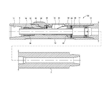
[0013] Figures 1 and 2 are cross-sectional views of a stabilizer 100 in
an extended
position and a retracted position, respectively, according to one embodiment
of the
present invention.
CA 02915251 2015-12-11
WO 2014/210539 PCT/US2014/044710
3
[0014] The stabilizer 100 may include a body 5, an adapter 7, a mandrel
10, one
or more seal sleeves 16, 17, and one or more arms 50. The body 5 may be
tubular
and have a longitudinal bore formed therethrough. Each longitudinal end 11, 12
of
the body 5 may be threaded for longitudinal and rotational coupling to other
members,
such as a drill string at one end 11 and the adapter 7 at the other end 12.
The body 5
may have an opening 51 formed through a wall thereof for accommodating an arm
50. The body 5 may also have a recess formed therein at least partially
defined by
shoulder 57 for receiving the lower seal sleeve 17. The body 5 may include a
profile
52 formed in a surface thereof for engaging each arm 50 adjacent the opening
51.
The upper seal sleeve 16 may be longitudinally coupled to the body 5 by a
threaded
connection. The lower seal sleeve 17 may be longitudinally coupled to the body
5 by
being disposed between the shoulder 57 and a top of the adapter 7. An end of
the
adapter 7 distal from the body 5 may be threaded for longitudinal and
rotational
coupling to another member of a bottom hole assembly (BHA). The BHA may
include
one or more tools such as a drill bit, a first underreamer, a second
underreamer, a
measuring while drilling tool, a logging while drilling tool, and combinations
thereof.
The BHA and the stabilizer may be coupled to a tubular string, such as a drill
pipe
string or a casing string.
[0015] The mandrel 10 may be a tubular having a longitudinal bore formed
therethrough, and may be disposed in the bore of the tubular body 5. The
mandrel 10
is coupled to the lower seal sleeve 17 using a coupling sleeve 22. The lower
end of
the mandrel 10 is abutted against the coupling sleeve 22, which in turn, is
releasably
connected to the lower seal sleeve 17 using a shearable member 23 such as a
shear
screw, a pin, or a collet. This arrangement prevents the arms 50 from
retracting
prematurely. In this embodiment, the coupling sleeve 22 is abutted to a
smaller
diameter portion at the lower end of the mandrel 10. In another embodiment,
the
mandrel 10 is connected to the lower seal sleeve 17 using a shearable member.
In
yet another embodiment, the arm 50 may be retained in the extended position
using a
shearable member that attaches the arm 50 to the body 5. In one example, each
of
the arms 50 may have a shear pin to retain the arm 50 against the body 5. A
lower
seal 32 is disposed between an outer surface of the mandrel 10 and an inner
surface
of the lower seal sleeve 17. An upper seal 31 may be disposed between the
upper
seal sleeve 16 and an outer surface of the mandrel 10. The upper seal 31 and
lower
seals 32 may be a ring or stack of seals, such as chevron seals, and made from
a
CA 02915251 2015-12-11
WO 2014/210539 PCT/US2014/044710
4
polymer, such as an elastomer. Various other seals, such as o-rings may be
disposed throughout the stabilizer 100. For example, an outer seal 36 may be
disposed between the upper seal sleeve 16 and the tubular body 5. As shown,
the
mandrel 10 is pressure balanced as a result of the upper seal 31 and the lower
seal
32 having the same size. As such, the mandrel 10 will not be moved by the
fluid
flowing through the stabilizer 100. In another embodiment, the lower seal 32
may be
larger than the upper seal 31 such that the mandrel 10 is no longer pressure
balanced. In this respect, the mandrel 10 may bias the arm 50 in the extended
position when fluid flows through the stabilizer.
[0016]
Each arm 50 may be movable between an extended position and a
retracted position and may initially be disposed in the opening 51 in the
extended
position, as shown in Figure 1. Each arm 50 may be pivotable relative to the
mandrel
10 via a fastener 25. A surface of the body 5 defining each opening 51 may
serve as
a rotational stop for a respective arm 50, thereby rotationally coupling the
arm 50 to
the body 5 (in both the extended and retracted positions). Each arm 50 may
include a
profile 53 (shown in Figure 2) formed in an inner surface thereof for engaging
the
corresponding profile 52. Movement of each arm 50 along the profile 52 forces
the
arm 50 radially outward from the retracted position to the extended position.
Each
profile 52, 53 may include a shoulder 62, 63. The shoulders 62, 63 may be
inclined
relative to a radial axis of the body 5 in order to secure each arm 50 to the
body 5 in
the extended position so that the arms 50 do not chatter or vibrate during
use. The
inclination of the shoulders 62, 63 may create a radial component of the
normal
reaction force between each arm 50 and the body 5, thereby holding each arm 50
radially inward in the extended position. Additionally, the shoulders 62, 63
may each
be circumferentially inclined (not shown) to retain the arms 50 against a
trailing
surface of the body 5 defining the opening 51 to further ensure against
chatter or
vibration.
[0017]
The arms 50 may be longitudinally aligned and circumferentially spaced
around the body 5. Optionally, junk slots 72 may be formed in an outer surface
of the
body 5 between the arms 50. The junk slots 72 may extend the length of the
openings 51 to maximize cooling and cuttings removal from the drill bit. The
arms 50
may be concentrically arranged about the body 5 to reduce vibration during
drilling.
The stabilizer 100 may include a plurality of arms 50, and each arm 50 may be
CA 02915251 2015-12-11
WO 2014/210539 PCT/US2014/044710
spaced circumferentially. In one embodiment, the stabilizer 100 is equipped
with
three arms 50, although the stabilizer 100 may have two, four, five, or more
arms.
The arms 50 may be made from a high strength metal or alloy, such as steel.
The
outer surface of the arms 51 may be arcuate, such as parabolic, semi-
elliptical, semi-
5
oval, or semi-super-elliptical. The arcuate arm shape may include a straight
or
substantially straight gage portion and curved leading and trailing ends.
[0018]
In use, the stabilizer 100 may be run into the wellbore in the configuration
shown in Figure 1. In this configuration, the arm 50 is prevented from
retracting due
to the shearable member 23.
[0019] In the event the stabilizer 100 becomes stuck, such as during
retrieval, an
upward force sufficient to shear the shearable member 23 is applied to the
stabilizer
100. In one example, the upward force urges the arm 50 against a restriction
in the
wellbore, which transfers the force to the shearable member 23 via the mandrel
10
and the coupling sleeve 22. The transferred force shears the shearable member
23,
which frees the coupling sleeve 22 to move downwardly and away from the
mandrel
10. No longer abutted by the coupling sleeve 22, the mandrel 10 is allowed to
move
relative to the body 5. A downward force from the restriction acting on the
arm 50
may be translated to the mandrel 10, thereby causing the mandrel to move
downwardly in the body 5. In turn, the arm 50 is moved along with the mandrel
10,
thereby rotating the arms inwardly to retract the arms, as shown in Figure 2.
In this
manner, the outer diameter of the stabilizer 100 is reduced to allow for
movement
through the restriction in the wellbore. As seen in Figure 2, the coupling
sleeve 22
may land on a shoulder formed at a lower portion of the seal sleeve 17.
[0020]
If fluid flow is restarted, the arms 50 will not re-extend because the
mandrel
10 is pressure balanced. In another embodiment, the mandrel 10 is not pressure
balanced and is biased upwards when the mud pumps are flowing. In yet another
embodiment, the stabilizer may include a locking device to retain the mandrel
10 in
the retracted position. For example, the locking device may be a collet such
as a
square shouldered collet. The fingers of the collet may expand into a recess
after the
arms 50 have retracted thereby locking the arms 50 and the mandrel 10 in the
retracted position. The locking device may prevent the arm 50 from extending
when
fluid is flowing through the mandrel 10.
CA 02915251 2015-12-11
WO 2014/210539 PCT/US2014/044710
6
[0021] Figures 3 and 4 illustrate another embodiment of a stabilizer
300. This
stabilizer 300 has many of the same features described with respect to the
stabilizer
100 shown in Figure 1. For sake of clarity, the same reference numbers will be
used
to denote the same features.
[0022] In this embodiment, the stabilizer 300 includes one or more fluid
ports 350
for selective fluid communication through the body 5. The fluid port 350 may
be
blocked by the coupling sleeve 322 when the arm 50 is in the extended
position, as
shown in Figure 3. The upper end of the coupling sleeve 322 abuts the mandrel
10
and is connected to the lower seal sleeve 17 using the shearable member 23.
The
lower end of the coupling sleeve 322 includes two seals 355 disposed between
the
coupling sleeve 322 and the body 5 and straddling the fluid port 350 for
blocking fluid
communication through the fluid ports 350. The coupling sleeve 322 also
includes
openings 360 adapted to align with the fluid ports 350 when the arms 50 are in
the
retracted position.
[0023] In use, the stabilizer 300 may be run into the wellbore in the
configuration
shown in Figure 3. In the event the stabilizer 300 becomes stuck, such as
during
retrieval, an upward force sufficient to shear the shearable member 23 may be
applied to the stabilizer 300. After shearing the shearable member 23, the
mandrel
10 is free to move in response to a force applied to the arm 50. A downward
force
from the restriction acting on the arm 50 causes the mandrel 10 and the
coupling
sleeve 322 to move downwardly. In turn, the arm 50 is moved along with the
mandrel
10, thereby allowing the arms to rotate inwardly to retract the arms, as shown
in
Figure 4. Also, the coupling sleeve 322 is moved to a position where the
openings
360 are aligned with the fluid port 350. In this manner, the outer diameter of
the
stabilizer 300 is reduced to allow for movement through a restriction in the
wellbore.
[0024] If fluid flow is restarted, the arms 50 will not re-extend
because the mandrel
10 is pressure balanced. However, the fluid is allowed to flow out of the
fluid ports
360. The fluid outflow may assist with fluid circulation and/or clearing the
annular
area between the stabilizer and the wellbore.
[0025] Figures 5 and 6 illustrate another embodiment of a stabilizer 500.
This
stabilizer 500 has many of the same features described with respect to
stabilizers
100, 300 shown in Figures 1 and 3. For sake of clarity, the same reference
numbers
CA 02915251 2015-12-11
WO 2014/210539 PCT/US2014/044710
7
will be used to denote the same features. Figures 5 and 6 are cross-sectional
views
of the stabilizer 500 in an extended position and a retracted position,
respectively.
Figures 5A and 6A are enlarged, partial cross-sectional views of the
stabilizer 500 of
Figures 5 and 6, respectively.
[0026] In this embodiment, the stabilizer 500 may include a body 5, an
adapter 7,
a mandrel 510, one or more seal sleeves 16, 17, and one or more arms 50. The
body
5 may be tubular and have a longitudinal bore formed therethrough.
Each
longitudinal end 11, 12 of the body 5 may be threaded for longitudinal and
rotational
coupling to other members, such as a drill string at one end 11 and the
adapter 7 at
__ the other end 12. The body 5 may have an opening 51 formed through a wall
thereof
for accommodating an arm 50. The body 5 may also have a recess formed therein
at
least partially defined by shoulder 57 for receiving the lower seal sleeve 17.
The body
5 may include a profile 52 formed in a surface thereof for engaging each arm
50
adjacent the opening 51. The upper seal sleeve 16 may be longitudinally
coupled to
__ the body 5 by a threaded connection. The lower seal sleeve 17 may be
longitudinally
coupled to the body 5 by being disposed between the shoulder 57 and a top of
the
adapter 7. An end of the adapter 7 distal from the body 5 may be threaded for
longitudinal and rotational coupling to another member of a bottom hole
assembly
(BHA).
[0027] The mandrel 510 may be a tubular having a longitudinal bore formed
therethrough, and may be disposed in the bore of the tubular body 5. The upper
end
of the mandrel 510 is at least partially disposed in the upper seal sleeve 16
and the
lower end of the mandrel 510 is at least partially disposed in the lower seal
sleeve 17.
A lower seal 32 is disposed between an outer surface of the mandrel 510 and an
__ inner surface of the lower seal sleeve 17. An upper seal 31 is disposed
between the
upper seal sleeve 16 and an outer surface of the mandrel 510. The upper seal
31
and lower seals 32 may be a ring or stack of seals, such as chevron seals, and
made
from a polymer, such as an elastomer. Various other seals, such as o-rings may
be
disposed throughout the stabilizer 500. For example, an outer seal 36 may be
__ disposed between the upper seal sleeve 16 and the tubular body 5. As shown,
the
mandrel 510 is pressure balanced as a result of the upper seal 31 and the
lower seal
32 having the same size. As such, the mandrel 510 will not move in response to
fluid
flowing through the stabilizer 500.
CA 02915251 2015-12-11
WO 2014/210539 PCT/US2014/044710
8
[0028]
A piston sleeve 535 is disposed between the mandrel 510 and a coupling
sleeve 522. The coupling sleeve 522, in turn, is releasably connected to a
retainer
sleeve 527 using a shearable member 523 such as a shear screw, a pin, or a
collet.
The retainer sleeve 527 may be threadedly connected to the body 5. This
arrangement prevents the arms 50 from retracting prematurely. In one
embodiment,
the piston sleeve 535 is movable relative to the coupling sleeve 522, the
mandrel 510,
or both. The piston sleeve 535 includes two seals 556, 557 disposed between
the
piston sleeve 535 and the body 5 and straddling the fluid port 550. The seals
556,
557 block fluid communication through the fluid ports 550 when the stabilizer
500 is in
the extended position. The upper seal 556 has a smaller diameter than the
lower seal
557. In this respect, the piston sleeve 535 is not pressure balanced. When
fluid is
flowing through the stabilizer 500, the piston sleeve 535 is urged upward to
help
retain the mandrel 510 and the arms 50 in the extended position. In this
embodiment,
the piston sleeve 535 is not attached to the coupling sleeve 522 and can move
upward relative to the coupling sleeve 522. This arrangement prevents the
piston
sleeve 535 from applying an upward force on the coupling sleeve 522 and the
shearable member 523 when fluid is flowing through the stabilizer 500.
[0029]
In one embodiment, the stabilizer 500 includes one or more fluid ports 550
for selective fluid communication through the body 5. The fluid ports 550 are
blocked
by the piston sleeve 535 when the arms 50 are in the extended position, as
shown in
Figures 5 and 5A. The piston sleeve 535 also includes openings 560 adapted to
align
with the fluid ports 550 when the arms 50 are in the retracted position.
[0030]
In use, the stabilizer 500 may be run into the wellbore in the extended
configuration shown in Figure 5. In this configuration, the arm 50 is
prevented from
retracting due to the shearable member 523 and the piston sleeve 535. When
fluid is
flowing through the stabilizer 500, the piston sleeve 535 is allowed to move
upward
relative to the coupling sleeve 522 to help maintain the arms 50 in the
extended
position.
[0031]
In the event the stabilizer 500 becomes stuck, such as during retrieval, an
upward force sufficient to shear the shearable member 523 is applied to the
stabilizer
500. For example, the tool string may be pulled upward to apply the upward
force to
the stabilizer. The upward force urges the arms 50 against a restriction in
the
wellbore, which transfers the force to the shearable member 523 via the
mandrel 510,
CA 02915251 2015-12-11
WO 2014/210539 PCT/US2014/044710
9
the piston sleeve 535, and the coupling sleeve 522. The transferred force
shears the
shearable member 523, which frees the coupling sleeve 522 to move downward and
away from the mandrel 510. No longer abutted by the coupling sleeve 522, the
mandrel 510 and the piston sleeve 535 are allowed to move relative to the body
5. A
downward force from the restriction acting on the arms 50 may be translated to
the
mandrel 510 and the piston sleeve 535, thereby causing the mandrel 510 and the
piston sleeve 535 to move downward in the body 5. Because the arms 50 are
moved
along with the mandrel 510, the arms 50 are rotated inwardly to retract the
arms 50,
as shown in Figures 6 and 6A. In this manner, the outer diameter of the
stabilizer 500
is reduced to allow for movement through the restriction in the wellbore. As
seen in
Figure 6A, the coupling sleeve 522 has landed on a shoulder formed at a lower
portion of the retainer sleeve 527.
[0032] If fluid flow is restarted, the arms 50 will not re-extend
because the mandrel
510 is pressure balanced and the upper seal 556 of the piston sleeve 535 is no
longer
engaged. As shown in Figure 6A, the upper seal 556 has moved into the retainer
sleeve 527, which has an inner diameter that is larger than the diameter of
the upper
seal 556. As a result, the upper seal 556 cannot sealingly engage the retainer
527.
Consequently, the fluid flow can no longer move the piston sleeve 535 upward
to urge
the mandrel 510 and the arms 50 to the extended position. Also, in the
retracted
position, the openings 560 of the piston sleeve 535 are in position for fluid
communication with the ports 550. The fluid is allowed to flow out of the
openings
560 and through the fluid ports 550. The fluid outflow may assist with fluid
circulation
and/or clearing the annular area between the stabilizer 500 and the wellbore.
In yet
another embodiment, the stabilizer may include a locking device to retain the
mandrel
510 in the retracted position.
[0033] In one embodiment, a method of drilling a wellbore includes
running a
drilling assembly into the wellbore through a casing string, the drilling
assembly
comprising a tubular string, a stabilizer, and a drill bit; applying a force
to an arm of
the stabilizer, thereby causing the arm to retract; and removing the
stabilizer and the
drill bit from the wellbore.
[0034] In one or more of the embodiments described herein, the arm of
the
stabilizer is run-in in an extended position.
CA 02915251 2015-12-11
WO 2014/210539 PCT/US2014/044710
[0035] In one or more of the embodiments described herein, a shearable
member
is used to retain the arm in the extended position.
[0036] In one or more of the embodiments described herein, the force
applied to
the arm is sufficient to shear the shearable member.
5 [0037] In one or more of the embodiments described herein, the
force is applied by
urging the arm against a restriction in the wellbore.
[0038] In one or more of the embodiments described herein, the method
also
includes opening a fluid port when the arm is retracted.
[0039] In another embodiment, a stabilizer for use in a wellbore
includes a tubular
10 body; a mandrel disposed in the tubular body; an arm rotatably coupled
to the
mandrel and movable between an extended position and a retracted position; and
a
coupling sleeve for retaining the arm in the extended position, wherein the
coupling
sleeve is releasably coupled to the tubular body.
[0040] In another embodiment, an assembly for forming a wellbore
includes a
tubular string; a drill bit coupled to the tubular string; an underreamer
coupled to the
tubular string; and a stabilizer coupled to the tubular string. The stabilizer
may
include a tubular body; a mandrel disposed in the tubular body; an arm
rotatably
coupled to the mandrel and movable between an extended position and a
retracted
position; and a coupling sleeve for retaining the arm in the extended
position, wherein
the coupling sleeve is releasably coupled to the tubular body.
[0041] In one or more of the embodiments described herein, a shearable
member
releasably couples the coupling sleeve to the tubular body.
[0042] In one or more of the embodiments described herein, a seal sleeve
is
attached to the body, and the coupling sleeve is releasably coupled to the
tubular
body via the seal sleeve.
[0043] In one or more of the embodiments described herein, the mandrel
is
pressure balanced.
[0044] In one or more of the embodiments described herein, the arm is
movable to
the retracted position when the coupling sleeve is released from the tubular
body.
CA 02915251 2015-12-11
WO 2014/210539 PCT/US2014/044710
11
[0045] In one or more of the embodiments described herein, a fluid port
is formed
in the tubular body.
[0046] In one or more of the embodiments described herein, the coupling
sleeve
blocks fluid communication through the fluid port when the arm is in the
extended
position.
[0047] In one or more of the embodiments described herein, a plurality
of seals are
disposed on the coupling sleeve for blocking fluid communication.
[0048] In one or more of the embodiments described herein, a piston
sleeve is
disposed between the mandrel and the coupling sleeve.
[0049] In one or more of the embodiments described herein, the piston
sleeve is
movable relative to the coupling sleeve.
[0050] In one or more of the embodiments described herein, a first seal
is
disposed on the piston sleeve and a second seal is disposed on the piston
sleeve,
wherein the second seal has a larger outer diameter than the first seal.
[0051] In one or more of the embodiments described herein, the piston
sleeve, the
first seal, and the second seal are configured to block fluid communication
through
the fluid port when the arm is in the extended position.
[0052] In one or more of the embodiments described herein, when the arm
is in
the extended position, the first seal is sealingly engaged with the body, and
wherein
when the arm is in the retracted position, the first seal is not sealingly
engaged with
any surface.
[0053] While the foregoing is directed to embodiments of the present
invention,
other and further embodiments of the invention may be devised without
departing
from the basic scope thereof, and the scope thereof is determined by the
claims that
follow.