Note: Descriptions are shown in the official language in which they were submitted.
CA 02915403 2015-12-14
,
=
WO 2013/185228
PCT/CA2013/050445
- I -
CONTINUOUSLY VARIABLE TRANSMISSION
FIELD OF THE INVENTION
[0001] The present invention relates to continuously
variable transmissions.
BACKGROUND
[0002] Personal tracked vehicles allow their riders to travel over
different
kinds of terrains. The best known example of a personal tracked vehicle is a
snowmobile. Other types include all-terrain vehicles outfitted with (usually
four)
tracks instead of wheels and stand-up personal tracked vehicles (such as the
one
shown in United States Patent No. 7,575,075).
[0003] In these types of vehicles, the track is typically driven by a
continuously variable transmission (CVT) connected to the track by a drive
sprocket
wheel. The vehicle's engine is connected to the CVT, and the CVT delivers
power
from the engine to the drive sprocket wheel as torque or rotational speed as
required
by the vehicle's speed and other driving conditions. Typically, at low vehicle
speeds or going up an incline, the rotational speed of the engine is greater
than that
of the drive sprocket wheel and the power from the engine is used to deliver a
large
torque to the drive sprocket wheel. Al high vehicle speeds and on level
ground, the
rotational speed of the engine is comparable to or greater than that of the
drive
sprocket wheel, the torque delivered to the drive sprocket wheel is smaller
and the
power from the engine is used to maintain the rotational speed of the drive
sprocket
wheel. The CVT provides an infinite number of gears or drive ratios (ratio of
rotational speed of the engine to rotational speed of the drive sprocket
wheel) to
allow better use of the engine's torque for different driving conditions.
[0004] This background information is provided for the
purpose of making
known information believed by the applicant to be of possible relevance to the
present invention. No admission is necessarily intended, nor should be
construed,
that any of the preceding information constitutes prior art against the
present
application.
CA 02915403 2015-12-14
=
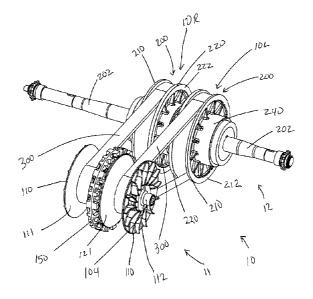
WO 2013/185228
PCT/CA2013/050445
- 2 -
SUMMARY
[0005] It is an object of the present invention to
ameliorate at least some of
the inconveniences present in the prior art.
[0006] In a first aspect there is provided a
continuously variable
5 transmission (CVT) system for a vehicle, including a driver pulley shaft,
adapted to
be operatively connected to an engine and adapted to be rotated by the engine,
a
driven pulley shaft parallel to the driver pulley shaft. A driver pulley
comprises a
first driver sheave and a second driver sheave having cones on opposing
surfaces,
each driver sheave being coaxially mounted on the driver pulley shaft for
rotation
10 therewith. The first driver sheave is moveable in an axial direction of
the driver
pulley shaft. The second driver sheave is fixed in the axial direction of the
driver
pulley shaft. A driven pulley comprises a first driven sheave and a second
driven
sheave having cones on opposing surfaces, each driven sheave being coaxially
mounted on the driven pulley shaft for rotation therewith. An endless belt is
15 supported between the opposing cones of the driver sheaves and the
opposing cones
at varying diameters. The endless belt is adapted to change the separation
between
the opposing cones of the driven pulley when the separation between the
opposing
cones of the driver pulley is changed. A roller weight guide is mounted on the
driver
pulley shaft adjacent to the first driver sheave on a side opposite to the
second driver
20 sheave. The roller weight guide is annular and has an inner periphery
and an outer
periphery. A plurality of guide rails are formed on the roller weight guide,
each
guide rail having an end near the inner periphery and another end near the
outer
periphery. A plurality of roller weights is mounted on the plurality of guide
rails. A
plurality of ramp structures extends in the radial direction on a surface of
the first
25 driver sheave adjacent to the roller weight guide, each of the plurality
of ramp
structures abutting one of the plurality of roller weights. Each of the
plurality of
roller weights is adapted to roll along at least one of the plurality of guide
rails in a
radial direction of the roller weight guide. The roller weights are adapted to
move
radially outwards with increasing rotation speed of the roller weight guide.
Each of
30 the plurality of guide rails is disposed parallel to one of the
plurality of ramp
structures. The first driver sheave moves towards the second driver sheave as
the
roller weights move radially outwards along the abutting ramp structures.
CA 02915403 2015-12-14
= .
=
WO 2013/185228
PCT/CA2013/050445
- 3 -
[0007] In a second aspect there is provided the driver
pulley is a left driver
pulley, the first driver sheave is a left inner driver sheave, the second
driver sheave
is a left outer driver sheave, the driven pulley shaft is a left driven pulley
shaft, the
driven pulley is a left driven pulley, the first driven sheave is a left inner
driven
sheave, the second driven sheave is a left outer driven sheave, each of the
plurality
of roller weights is a left roller weight, and the endless belt is the left
endless belt.
The CVT system further includes a right driven pulley shaft coaxially with the
left
driven pulley shaft, and a right driven pulley comprising a right inner driven
sheave
and a right outer driven sheave mounted on the right driven pulley shaft to
rotate
therewith. Opposing surfaces of the right inner and right outer driven sheaves
comprise opposing cones. A right driver pulley comprises a right inner driver
sheave and a right outer driver sheave mounted on the driver pulley shaft to
rotate
therewith. Opposing surfaces of the right inner and right outer driver sheaves
comprise opposing cones. The right inner driver sheave is adjacent to the
roller
weight guide. A plurality of ramp structures on a surface of the right inner
driver
sheave is adjacent to the roller weight guide. Each ramp structure of the
right inner
driver sheave coincides with one of the plurality of ramp structures of the
left inner
driver sheave. A right endless belt is supported between the opposing cones of
the
right driver pulley and the opposing cones of the right driven pulley. The
right and
left inner driver sheaves are moveable in the axial direction. The right and
left outer
driver sheaves are fixed in the axial direction. The right and left outer
driven
sheaves are moveable in the axial direction. A right roller weight is mounted
on the
roller weight guide adjacent to each left roller weight of the plurality of
roller
Weights to form a plurality of roller Weight pairs, each right roller weight
abutting
one of the plurality of ramp structures of the right inner driven sheave.
[0008] In a third aspect there is provided a vehicle
comprises an engine
having a crankshaft, one of a pair of wheels and a pair of tracks, and a CVT
system
according to the above aspects. The crankshaft is connected to the driver
pulley
shaft. A left one of the one of the pair of wheels and the pair of tracks is
connected
to the left driven pulley shaft, and a right one of the one of the pair of
wheels and
the pair of tracks is connected to the right driven pulley shaft.
CA 02915403 2015-12-14
WO 2013/185228
PCT/CA2013/050445
- 4 -
[0009] In a fourth aspect there is provided a driver pulley assembly
for a
continuously variable transmission (CVT) is provided. The driver pulley
assembly
includes a roller weight guide adapted to be mounted on a driver pulley shaft
of the
CVT, the roller weight guide being annular and having an inner periphery and
an
outer periphery:. A plurality of ramp windows extending radially along the
roller
weight guide is also included. Each ramp window includes a pair of guide rails
extending along opposite edges of the ramp window. A roller weight is mounted
on
the pair of guide rails, the roller weight being adapted to roll along the
pair of guide
rails in a radial direction of the roller weight guide. A ramp structure
coincides with
the ramp window, the ramp structure extending in the radial direction of the
roller
weight guide and abutting the roller weight. The roller weight is adapted to
move
radially outwards along the ramp structure with increasing rotation speed of
the
roller weight guide.
[0010] More particularly, in a fifth aspect there is provided a
continuously
variable transmission (CVT) system for a vehicle, comprising a main shaft,
adapted
to be operatively connected to an engine and adapted to be rotated by the
engine; a
drive shaft parallel to the main shaft; a driver pulley comprising a moveable
sheave
and a fixed sheave having cones on opposing surfaces, each of said moveable
sheave and said fixed sheave being coaxially mounted on the main shaft for
rotation
therewith; the moveable sheave being moveable in an axial direction of the
main
shaft; the fixed sheave being fixed in the axial direction of the main shaft;
a driven
pulley comprising a steering sheave and a torque-sensing sheave having cones
on
opposing surfaces, the steering sheave and torque-sensing sheave being
coaxially
mounted on the drive shaft for rotation therewith; an endless belt, supported
between the opposing cones of the moveable sheave and the fixed sheave and the
opposing cones of the steering sheave and the torque-sensing sheave, the
endless
belt being adapted to change the separation between the opposing cones of the
steering sheave and the torque-sensing sheave when the separation between the
opposing cones of the moveable sheave and the fixed sheave is changed: a
roller
weight guide mounted on the main shaft adjacent to the moveable sheave on a
side
opposite to the fixed sheave, the roller weight guide having an inner
periphery and
an outer periphery; a plurality of guide rails on the roller weight guide,
each guide
rail having an end near the inner periphery and another end near the outer
periphery;
CA 02915403 2015-12-14
. 1
WO 2013/185228
PCT/CA2013/050445
- 5 -
a plurality of roller weights mounted on the plurality of guide rails; a
plurality of
ramp structures extending in the radial direction on a surface of the moveable
sheave adjacent to the roller weight guide, each of the plurality of ramp
structures
abutting one of the plurality of roller weights; each roller weight of the
plurality of
5 roller weights being adapted to move along at least one of the plurality
of guide rails
in a radial direction of the roller weight guide; each roller weight being
adapted to
move radially outwards with increasing rotational speed of the roller weight
guide;
each guide rail of the plurality of guide rails being disposed substantially
parallel to
one of the plurality of ramp structures; the moveable sheave moving towards
the
10 fixed sheave as the roller weights move radially outwards along abutting
ramp
structures.
[0011] In sixth aspect the driver pulley is a left driver
pulley; the moveable
sheave is a left moveable sheave; the fixed sheave is a left fixed sheave; the
drive
shaft is a left drive shaft; the driven pulley is a left driven pulley; the
steering sheave
15 is a left steering sheave; the torque-sensing sheave is a left torque-
sensing sheave;
each of the plurality of roller weights is a left roller weight; and the
endless belt is a
left endless belt; and the CVT system further comprises a right driven pulley
comprising a right steering sheave and a right torque-sensing sheave coaxially
mounted on the right drive shaft to rotate therewith, opposing surfaces of the
right
20 steering sheave and the right torque-sensing sheave comprising opposing
cones: a
right driver pulley comprising a right moveable sheave and a right fixed
sheave
coaxially mounted on the main shaft to rotate therewith, opposing surfaces of
the
right moveable sheave and the right fixed sheave comprising opposing cones,
the
right moveable sheave being adjacent to the roller weight guide; a plurality
of ramp
25 structures extending in the radial direction on a surface of the right
moveable sheave
adjacent to the roller weight guide; and a right endless belt, supported
between the
opposing cones of the right moveable sheave and the right fixed sheave and the
opposing cones of the right steering sheave and the right torque-sensing
sheave, the
right endless belt being adapted to change the separation between the opposing
30 cones of the right steering sheave and the right torque-sensing sheave
when the
separation between the opposing cones of the right moveable sheave and the
right
fixed sheave is changed; wherein the right and left moveable sheaves are
moveable
in the axial direction; the right and left fixed sheaves are fixed in the
axial direction:
=
CA 02915403 2015-12-14
=
WO 2013/185228
PCT/CA2013/050445
- 6 -
the right and left torque-sensing sheaves are moveable in the axial direction;
a
plurality of right roller weights mounted on the plurality of guide rails each
of the
plurality of ramp structures abutting one of the plurality of roller weights
each of the
left and right roller weights being adapted to move radially outwards with
increasing rotational speed of the roller weight guide; and the right moveable
sheave
moving towards the right fixed sheave as the right roller weights move
radially
outwards along abutting ramp structures.
[0012] In a
seventh aspect there is provided a vehicle comprising a motor
having an output shaft; one of at least two wheels and a pair of tracks; and a
CVT
system according to the fifth or sixth aspect wherein the output shaft is
connected to
the main shaft: a left one of one of the at least two wheels and the pair of
tracks is
connected to the left drive shaft; and a right one of one of the at least two
wheels
and the pair of tracks is connected to the right drive shaft.
[0013] In an eight aspect
there is provided a driver pulley assembly for a
continuously variable transmission (CVT), comprising: a roller weight guide
adapted to be mounted on a main shaft of the CVT, the roller weight guide
having
an inner periphery and an outer periphery, a plurality of ramp windows
extending
radially along the roller weight guide; each ramp window including a pair of
guide
rails extending along opposite edges of the ramp window: a roller weight
mounted
on the pair of guide rails, the roller weight being adapted to move along the
pair of
guide rails in a radial direction of the roller weight guide; and a ramp
structure
coinciding with the ramp window, the ramp structure extending in the radial
direction of the roller weight guide and abutting the roller weight; the
roller weight
being adapted to move radially outwards along the ramp structure with
increasing
rotational speed of the roller weight guide.
[0014] For
purposes of the present application, terms related to spatial
orientation when referring to a continuously varying transmission and
components
in relation to the continuously varying transmission, such as "forwardly-,
"rearwardly",
"right-, -above- and "below-. are as they would be understood
by a driver of a vehicle to which the transmission is connected, with the
continuously varying transmission connected to the underside of the of the
vehicle.
CA 02915403 2015-12-14
=
=
WO 2013/185228
PCT/CA2013/050445
- 7 -
in a straight ahead orientation (i.e. not steered left or right), and in an
upright
position (i.e. not tilted). The explanations provided above regarding the
above terms
take precedence over explanations of these terms that may be found in any one
of
the documents incorporated herein by reference.
5 [0015] Embodiments of the present invention each have at least one of
the
above-mentioned object and/or aspects, but do not necessarily have all of
them. It
should be understood that some aspects of the present invention that have
resulted
from attempting to attain the above-mentioned object may not satisfy these
objects
and/or may satisfy other objects not specifically recited herein.
10 [0016] Additional and/or alternative features, aspects, and
advantages of
embodiments of the present invention will become apparent from the following
description, the accompanying drawings, and the appended claims.
BRIEF DESCRIPTION OF THE DRAWINGS
[0017] For a better understanding of the present
invention, as well as other
15 aspects and further features thereof, reference is made to the following
description
which is to be used in conjunction with the accompanying drawings, where:
[0018] Figure 1 is a perspective view taken from a
front, right side of a
personal dual-tracked vehicle;
[0019] Figure 2 is a right side elevation view of a
portion of the personal
20 dual-tracked vehicle of Figure 1;
[0020] Figure 3A is a left side elevation view of a
continuously variable
transmission (CVT) in accordance with one embodiment of the present
application
connected to an engine:
[0021] Figure 3B is a perspective view taken from the
top, left side of the
25 continuously variable transmission (CVT) of Figure 3A connected to an
engine:
[0022] Figure 3C is a top plan view of the CVT of
Figure 3B connected to
an engine;
CA 02915403 2015-12-14
=
=
WO 2013/185228
PCT/CA2013/050445
- 8 -
[0023] Figure 3D is a left side elevation view
illustrating the CVT of
Figures 3A-C housed in a closed housing chamber.
[0024] Figure 3E is a perspective view taken from the
top, left side of the
continuously variable transmission (CVT) of the present application shown in
5 isolation;
[0025] Figure 3F is a top plan view of the CVT of the
present application
shown in isolation;
[0026] Figure 4A, 4B and 4C are, respectively, a
perspective view taken
from the top, left side; a front elevation view; and a top plan view of the
driver
10 pulley assembly of the CVT of Figure 3E;
[0027] Figure 5A and 5B are cross-sectional views, taken
respectively along
the line A-A and B-B, of the driver pulley assembly of Figure 3E showing the
driver
pulley assembly in a disengaged configuration, with the belt removed for
clarity:
[0028] Figure 6A and 6B are cross-sectional views, taken
respectively along
15 the line A-A and B-B, of the driver pulley assembly of Figure 3E showing
the driver
pulley assembly in an underdrive configuration, with the belt removed for
clarity:
[0029] Figure 7A and 7B are cross-sectional views, taken
respectively along
the line A-A and B-B, of the driver pulley assembly of Figure 3E showing the
driver
pulley assembly in an overdrive configuration, with the belt removed for
clarity;
20 [0030] Figure 8 shows various views of the roller weight guide of the
CVT
of Figure 3E; Figure 8A is a left side elevation view. Figure 88 is a front
plan view;
Figure 8C is a perspective view taken from a front, left side of the roller
weight
guide; Figure shows various views of a two piece roller weight guide of the
CVT of
Figure 3E: Figure 8D is a left side elevation view, Figure 8E is a front plan
view;
25 and Figure 8F is a perspective view taken from a front, left side of the
roller weight
guide;
[00311 Figure 9 shows various views of a roller weight
button or slider of
the CVT of Figure 3E, Figure 9A is a perspective view taken from the front,
left
CA 02915403 2015-12-14
=
WO 2013/185228
PCT/CA2013/050445
- 9 -
side; Figure 9B is a top plan view; Figure 9C is a front elevation view; and
Figure
9D is a rear elevation view;
[0032] Figure 10 shows various views of a roller weight
of the CVT of
Figure 3E, Figure 10A is a perspective view taken from the front, left side;
Figure
5 10B is a top plan view; and Figure 10C is a cross-section taken along the
line B-B
of Figure 10B;
[0033] Figure 11 shows various views of a male moveable
sheave of the
CVT of Figure 3E, Figure 11A is a perspective view taken from the front, left
side;
Figure 11B is a left side elevation view; Figure 11C is a rear elevation view;
Figure
10 I 1D is a right side elevation view; Figure 11E is a cross-section taken
along the
line A-A of Figure 11B; and Figure 11F is a cross-section taken along the line
B-B
of Figure 11B;
[0034] Figure 12 shows various views of a female moveable
sheave of the
CVT of Figure 3E, Figure 12A is a perspective view taken from the rear, right
side;
15 Figure 12B is a right side elevation view; Figure 12C is a front
elevation view:
Figure 12D is a left side elevation view; Figure 12E is a cross-section taken
along
the line A-A of Figure 13B; and Figure 12F is a cross-section taken along the
line
B-B of Figure 12B;
[0035] Figure 13 is a perspective view, taken from a
front, right side, of a
20 portion of the roller weight assembly of the CVT of Figure 3E showing a
portion of
the male moveable sheave with a roller weight button or slider and a roller
weight
mounted thereon:
[0036] Figure 14 is a perspective view, taken from a
front, right side, of a
portion of the roller weight assembly of the CVT of Figure 3E showing a
portion of
25 the roller weight guide with a roller weight button or slider and a pair
of roller
weights mounted thereon:
[0037] Figure 15 is a left side elevation view of the
roller weight assembly
of the CVT of Figure 3E, with the female moveable sheave removed for clarity-,
and
showing the male moveable sheave and the roller weight guide having mounted
30 thereon a plurality of roller weight buttons or sliders and pairs of
roller weights;
CA 02915403 2015-12-14
. =
WO 2013/185228
PCT/CA2013/050445
- 10 -
[0038] Figure 16 is a close-up of the cross-sectional
view of a low speed
ramp (clutch ramp) and a high speed ramp (shift ramp) of the male moveable
sheave
of Figure 11E and 11F. taken respectively along the lines A-A and B-B;
[0039] Figure 17A and 17B are respectively, a
perspective view taken from
5 the front, left side: and a front elevation view of the driven pulley
assembly of the
CVT of Figure 3A:
[0040] Figure 18A is a perspective view taken from a
front, left side of the
left inner driven sheave of the CVT of Figure 3A; and Figure 18B is a
perspective
view taken from the top. left side of the left outer driven sheave of the CVT
of
10 Figure 3A;
[0041] Figure 19A is a perspective view taken from a
front, right side of the
left helix of the CVT of Figure 3A; Figure 19B is a perspective view taken
from a
front, right side of the left helix holder of the CVT of Figure 3A; Figure 19C
is a
perspective view taken from a front, right side of the left helix of the CVT
of Figure
15 3A depicting the left helix and left helix holder as a single piece; and
Figure 19D is
a perspective view taken from a rear, right side of the left helix and left
helix holder
of the CVT of Figure 3A depicting the left helix and left helix holder as a
single
piece;
[0042] Figure 20A is a cross-section taken along the
line A-A of the driven
20 pulley assembly of Figure 17, showing the driven pulley assembly in a
disengaged
or underdrive configuration with the belt removed for clarity;
[0043] Figure 20B is a cross-section taken along the
line A-A of the driven
pulley assembly of Figure 17, showing the driven pulley assembly in an
overdrive
configuration with the belt removed for clarity;
25 [0044] Figure 21 is a top plan view of a portion of a vehicle
according to
another embodiment, with the platform removed for clarity and showing the
steering system connected to the CVT; and
[0045] Figure 22 is a cross-section, taken along the
line A-A, of the portion
of the vehicle of Figure 21.
- = CA 02915403 2015-12-14
. =
WO 2013/185228
PCT/CA2013/050445
- 11 -
DETAILED DESCRIPTION
[0046] Although a personal stand-up dual tracked vehicle
is being described
herein, it is contemplated that other embodiments could include other kinds of
personal tracked vehicles, for example. a straddle-seat, dual-tracked vehicle.
Other
5 embodiments relate to wheeled vehicles.
[0047] With reference to Figures I and 2, a personal
stand up dual-tracked
vehicle I has a platform 2 mounted over a pair of left and right tracks, 4 and
5. The
left and right tracks 4. 5 are laterally spaced and define a longitudinal axis
3 of the
vehicle I. The vehicle 1 has a frame 6 and a suspension assembly 7 connected
to the
10 frame 6 supporting the endless tracks 4. 5. An engine 8, located between
the tracks
4 and 5 below the platform 2, is also connected to the frame 6.
[0048] The vehicle I is designed to be driven with a
rider standing on the
platform 2. The tracks 4. 5 extend laterally further than the platform 2, and
the
engine 8 and other components of the vehicle 1 are disposed between the tracks
4, 5
15 below the platform 2 so that the center of gravity of the vehicle 1 is
generally low,
for stability of the vehicle 1 even with a rider standing on the platform 2.
[00491 A handlebar 18 (shown in FIG. 2) with a throttle
control 20 controls
the engine 8. The handlebar 18 extends upwards so that the throttle control 20
is at a
level of rider's hands with the rider in a standing position. Alternatively,
the vehicle
20 1 can also be provided with a cable connected to the throttle control 20
instead of
the handlebar 18. It is also contemplated that the engine controls could be
connected wirelesslv to the engine and remotely controlled by the rider of the
vehicle 1.
[0050] The engine 8 propels the vehicle 1 by driving the
endless tracks 4, 5.
25 The engine 8 is operatively connected to the endless tracks 4, 5 by a
dual drive
continuously variable transmission (ddCVT) 10, which will be discussed in
further
detail below. The engine 8 is coupled to the ddCVT 10 by a crankshaft 14
(Figure
5A). The ddCVT 10 is connected to each track 4, 5 by a chain 44 and drive
sprocket wheel 40 at the rear of the vehicle 1. Although the drive wheel
depicted in
30 Figure 1 is a drive sprocket wheel any type of drive wheel can be
connected to the
CA 02915403 2015-12-14
. =
WO 2013/185228
PCT/CA2013/0504-15
- 12 -
ddCVT for driving the ddCVT. for example, a drive wheel connected to a pulley,
belt or gear.
[0051]
The vehicle 1 is steered by selectively driving one of the tracks 4, 5
faster than the other of the tracks 4. 5. Steering of the vehicle 1 is
controlled by
5 pivoting the platform 2. A steering system 16, comprising a steering rod
203
(Figures 20A 20B and 22) couples the platform 2 to the ddCVT 10 for steering
the
vehicle 1. When the platform 2 pivots about the longitudinal axis 3 to the
right side,
the left track 4 is driven faster than the right track 5 thereby steering
vehicle 1
towards the right side. Similarly, when the platform 2 pivots about the
longitudinal
10 axis 3 towards the left, the right track 5 is driven faster than the
left track 4 thereby
steering vehicle 1 towards the left. In some embodiments, the steering system
16
comprises a differential connected between the platform 2 and the ddCVT 10 for
steering the vehicle 1. In some embodiments, the steering system 16 can
comprise a
different control mechanism, or a control assist mechanism located elsewhere
on the
15 vehicle 1. Hydraulics can be used as an alternate control or control
assist
mechanism for the steering system 16.
[0052]
The platform 2 has a forward portion 22, a central portion 24. and a
rearward portion 26. The platform 2 has a right side 28 and a left side 30.
The
forward and rearward portions, 22 and 26, which are upwardly inclined with
respect
20 to the central portion 24, act as front and rear foot rests,
respectively. The platform
2 is pivotably connected to the frame 6 and selectively tilted by the rider by
selectively applying a greater fraction of weight to the left or right sides,
28 or 30,
of the platform 2. It is also contemplated that the steering assembly 16 could
be
configured such that a rightward tilt of the platform 2 corresponds to a
leftward
25 steering position and vice versa.
[0053]
When riding the vehicle 1, the rider places his/her feet on the forward
and rearward portions 22, 26 such that the central portion 24 is disposed bete
en
his/her legs. The rider usually twists his/her torso with respect to his/her
legs so as
to be able to look forward, similar to a skateboard rider. The positioning of
the feet
30 on the forward and rearward portions, 22 and 26, permits the rider to
control the
tilting of the platform 2 while minimizing chances of the rider becoming
unbalanced. US Patent No. 7.575,075. issued August 18, 2009, which is
CA 02915403 2015-12-14
=
=
WO 2013/185228
PCT/CA2013/050445
- 13 -
incorporated herein by reference, describes a personal tracked vehicle having
a
platform which is pivoted to steer the vehicle.
[0054]
With reference to Figures 3A, 3B. 3C and 3D, the ddCVT 10,
includes a driver pulley assembly 11, disposed towards the front of the
vehicle 1,
5 and a driven
pulley assembly 12, disposed towards the rear of the vehicle 1. The
driver pulley assembly 11 of the ddCVT 10 is connected to the crankshaft 14
(Figure 5A) of the engine 8 while the driven pulley assembly 12 is connected
to the
drive sprocket wheels 40 (Figure 21) at the rear of the vehicle 1. It is
however also
contemplated that the drive sprocket wheels could be disposed at the front of
the
10 vehicle 1, and
the driven pulley assembly 12 could be disposed towards the front of
the vehicle 1 with the driver pulley assembly disposed towards the rear of the
vehicle 1. In other embodiments, the engine 8 can be any power source with an
output shaft, for example and electric motor or an hydraulic motor.
[0055]
The ddCVT 10 has a pair of parallel CVTs, including a left CVT IOL
15 and a right CVT
10R. The left and right CVTs, IOL and 10R, are generally mirror
images of each other. Corresponding features of the left and right CVTs, 10L
and
10R, are denoted by a common reference number, in the discussion below. When
referring to features that are similar on the left and right sides, the
components will
be referred to only by the common reference number and without using "L" and
"R-
20 to distinguish
between the left and right side components (for example, -CVTs 10"
instead of -left and right CVTs, 10L and 10R"). When discussing features that
are
different on the left and right sides, the corresponding left and right sides
features
may be distinguished, for clarity, using "L- and "R" after the reference
number, or
by using different reference numbers for them.
25 [0056] Each CVT 10L,
IOR comprises a driver pulley 100, a driven pulley
200. and the endless belt 300 coupling the driver and the driven pulleys, 100
and
200. The drier pulleys 100L, 100R form part of the driver pulley assembly 11.
The
driven pulleys 200L, 200R form part of the driven pulley assembly 12. The
driver
and driven pulleys, 100 and 200, are variable diameter pulleys. The belt 300
defines
30 the effective
diameter of the driver and the driven pulleys, 100 and 200. The
effective diameter of the pulleys 100, 200 is varied by changing the radial
position
at which the belt 300 is held in the pulleys 100, 200.
= = CA 02915403 2015-12-14
=
WO 2013/185228
PCT/CA2013/050445
- 14 -
[0057]
With reference to Figures 4A to 7B the left and right driver pulleys
100 each comprise an inner or moveable sheave 120 and an outer or fixed sheave
110. The fixed sheaves 110, 110 are fixed in the axial direction while the
moveable
sheaves 120 are moveable in the axial direction. The belts 300, 300, are
disposed
5 between the
fixed sheaves 110, 110 and moveable sheaves 120, 120. Therefore, the
radial position of the belt 300 in the driver pulleys 100, 100 can be
controlled by
controlling the axial position of the moveable sheaves 120. 120.
[0058]
With reference to Figures 3C, 20A, 20B, and 22 the left and right
driven pulleys 200, 200 each comprise an outer or torque-sensing sheave 210
and an
10 inner or
steering sheave 220. Both the torque sensing sheaves 210, 210 and the
steering sheaves 220, 220 can move axially relative to the transmission
housing.
However, the axial position of the steering sheaves 220. 220 are actively
controlled
by the vehicle rider, while the axial position of the torque sensing sheaves
210, 210
are passively controlled by several opposing variable axial forces as
discussed in
15 detail below.
The left and right driven pulleys 200, 200 are respectively mounted on
left and right drive shafts 202, 202 and coupled by a steering rod 203
(Figures 3C.
20A, 20B and 22) to form the driven pulley assembly 12. The left and right
driven
pulleys 200 each comprise an outer or torque-sensing sheave 210 and an inner
or
steering sheave 220 (Figure 3B). The steering rod 203 (Figures 20A. 20B and
22) is
20 coupled to the
inner steering sheaves 220. Each of the left and right drive shafts,
202 and 202, is coupled to the respective endless track. 4 and 5, via a chain
44 and a
drive sprocket wheel 40 (shown in Figure 21).
[0059]
Opposing surfaces of the outer fixed sheaves 110 and inner moveable
sheaves 120, and the torque¨sensing sheave 210 and the steering sheave 220. of
25 each pulley 100,
200 have conical surfaces, 1 1 1 and 121, 211 and 221. The belt 300
is held between the opposing conical surfaces, 111 and 121. 211 and 221. The
radial
position of the belt 300 varies with the separation of the opposing conical
surfaces,
111 and 121, 211 and 221, thereby changing the effective diameter of the
pulleys,
100 and 200. Increasing the separation between the opposing conical surfaces,
1 1 1
30 and 121, 211 and
221, results in the belt 300 moving inwards towards the respective
main or drive shafts, 102 or 202, thereby decreasing the effective pulley
diameter.
Similarly, the effective diameter of the pulleys 100, 200 can be increased by
CA 02915403 2015-12-14
= .
WO 2013/185228
PCT/CA2013/050445
- 15 -
decreasing the separation between opposing conical surfaces, 1 1 1 and 121,
211 and
221.
[0060] As can be seen in Figure 3D, the ddCVT 10 is housed
in a closed
housing chamber 320 having an inlet 322 for drawing in cool air to cool the
ddCVT
10, and an outlet 324 from which the heated air exits the housing 320 after
cooling
the ddCVT system 10.
Driver Pulley Assembly
[0061] The driver pulley assembly 11 \ ki 1 1 now be
discussed with reference
to FIGs 4, 5A and 5B. The outer sheaves 110 of the driver pulley assembly 11
are
fixed sheaves 110, mounted at an end of the main shaft 102 and fixed with
respect
to motion in the axial direction of the main shaft 102. The inner sheaves 120
of the
driver pulley assembly 11 are moveable sheaves 120. mounted near the middle of
the main shaft 102 and moveable along the main shaft 102 towards and away from
the corresponding fixed driver sheaves 110 to vary the diameter of the driver
pulleys
100. The fixed and moveable sheaves, 110 and 120, are coupled to the main
shaft
102 to rotate as a unit with the main shaft 102 about its longitudinal axis.
The
driver pulley assembly ll can be constructed in several different
configurations
depending upon the desired combination of torque and speed required by the
ddCVT. In one embodiment one of the outer sheaves 110 is fixed and the other
is
moveable and controlled by a variator and the inner sheaves 120 are moveable.
In
yet another embodiment both outer sheaves 110 are moveable and controlled by
variators and the inner sheaves 120 are moveable. Again in each configuration
the
fixed sheave or sheaves are fixed rotationally and axially to the main shaft
102, the
moveable sheave or sheaves are fixed rotationally but not axially to the main
shaft
102. This allows the fixed and moveable sheaves that are coupled to the main
shaft
to rotate as unit with the main shaft 102 about the longitudinal axis.
[0062] The roller weight assembly 150, comprising a roller
weight guide
152, a plurality of roller weights 154. and a plurality of roller 'Weight
buttons or
sliders 156, is centered by and located between the left and the right
moveable
sheaves 120L and 120R. The roller weight assembly 150 is coupled to the
moveable
sheaves 120, 120 to form a clutch/variator for rotating with the main shaft
102 and
. CA 02915403 2015-12-14
WO 2013/185228
PCT/CA2013/050445
- 16 -
for moving the moveable sheaves 120, 120 along the main shaft 102 towards and
aw ay from the corresponding fixed sheaves 110, 110.
[0063] The fixed and moveable sheaves 110 and 120,
respectively, and the
roller weight guide 152 are annular structures, each having an outer periphery
and
an inner periphery best viewed in Figures 4A, 4B and 4C. As explained above,
opposing surfaces, 1 1 I of fixed sheaves 110 and 121 of moveable sheaves 120,
of
each driver pulley 100 have opposing cones. The surfaces 122 of the moveable
sheaves 120 facing the roller weight guide 152 have ramp structures 125. 128,
which couple to the roller weight assembly 150, which will be discussed in
further
detail below. The outer surface 112 of the left fixed driver sheave 110 has
fin-like
structures 114.
[0064] The left fixed sheave 110 is in proximity to the air
inlet 322 of the
chamber 320 housing the ddCVT 10, and the fin-like structures 114 act as
impellers
drawing air through the inlet 322 into the chamber 320 for cooling the ddCVT
10
(Figure 3D). It is contemplated that the outer surface 212 of the left outer
torque-
sensing sheave 210 could have fin-like structures and that the air inlet could
be
disposed near the driven pulleys 200 instead of the driver pulley 100. The
outer
surface of each steering sheave is designated 222 the Figures. It is also
contemplated that chamber 320 has more than one air inlet. It is contemplated
that
the ddCVT 10 could be housed in a partially closed chamber or not be housed in
a
closed chamber in which case the fin-like structures 114 on the left fixed
sheave 110
may not be needed for cooling. The fin-like structures 114 (Figure 4A) on the
left
fixed sheave 110 can also be omitted if the ddCVT 10 is housed in a closed
chamber
is provided with other means of cooling.
[0065] With reference now to Figures 5A and 5B, the main shaft 102 is a
hollow shaft, having a pair of coaxial and adjacent left and right spring
holders 106,
106 disposed inside. A driver spring 105 is disposed within the adjacent
spring
holders 106 between end walls 107 at their outer ends. The spring holders 106,
and
the driver spring 105 are coaxial with the main shaft 102 and rotate with it.
The left
and right spring holders 106 are moveable in the axial direction and coupled
to the
moveable sheaves 120. The left and right movable sheaves 120, 120 are coupled
to
the spring holders 106. 106 of the opposite side by keys 108 (Figure 5A) such
that
CA 02915403 2015-12-14
= .
WO 2013/185228
PCT/CA2013/050445
- 17 -
when the moveable sheaves 120. 120 are moved away from each other (by the
roller
weight assembly 150. as discussed below), the spring holders 106, 106 are
pushed
closer together compressing the spring 105. The end wall 107 of the left
spring
holder 106 is in the form of a removable cap to facilitate assembly and
maintenance.
5 In an alternative embodiment the end wall 107 is fixed and cannot be
removed.
100661 The crankshaft 14 of the engine 8 is inserted
from the right side into
the main shaft 102 through the right collar 104 and the end wall 107 of the
right
spring holder 106 into the center of the spring 105. A cap screw 109 is
inserted
from the left side into the main shaft 102 through the left collar 104 and the
end wall
10 107 of the left spring holder 106 into the end of the crankshaft 14 in
the center of
the spring 105 to fasten the driver pulley assembly 11 together. The preload
of the
cap screw 109 creates a friction force between the clamped elements (104, 110,
102,
110, 190) resulting in the elements rotating as a unit with the crankshaft.
The
moveable sheaves 120 and the roller weight assembly 150 are rotationally
coupled
15 together to rotate as a unit. The moveable sheaves 120 are rotationally
coupled to
the main shaft 102 by a plurality of keys 108 so that moveable sheaves 120 and
the
roller weight assembly 150 rotate as a unit with the crankshaft 14.
[0067] In this embodiment, the crankshaft 14 of the
engine 8, is connected
to the main shaft 102 from the right side, however, in other embodiments, the
20 crankshaft 14 can be connected to the main shaft 102 from the left side.
The
moveable sheaves 120 and the roller weight assembly 150 will be discussed in
more
detail below.
Roller Weight Assembly
[0068] Turning to Figures 5 to 16, the roller weight
assembly 150 will now
25 be discussed. With reference to Figures 13, 14 and 15, the roller weight
assembly
150 comprises a roller weight guide 152, a plurality of roller weight buttons
or
sliders 156. a plurality- of roller weights 154 and a plurality of ramp
structures, 125
and 128. The roller weights 154 are rotatably mounted on a pair of opposing
roller
weight buttons or sliders 156 which are slidably mounted on roller weight
guide
30 152. The roller weight guide 152 is mounted on the main shaft 102
between the two
CA 02915403 2015-12-14
,
WO 2013/185228
PCT/CA2013/050445
- 18 -
movable sheaves 120. The ramp structures, 125 and 128, are formed on the
surface
122 of the moveable sheaves 120, 120 adjacent to the roller weight guide 152.
[00691 With
reference to Figure 11, 12 and 13. mov cable sheaves 120 have
radially extending ramp structures, 125 and 128, on the surfaces 122 facing
the
roller weight guide 152. As can be clearly seen in Figure 11, the right
moveable
driver sheave 120 has eight equally spaced ramps 125 comprising alternating
ramps
125A and 125B. Each ramp, 125A or 125B, generally referred to as ramp 125,
extends radially from an outer edge 142 near the outer periphery to an inner
edge
143 near the inner periphery of the moveable sheave 120. The height of ramp
125
(with respect to a plane perpendicular to the axial direction of the main
shaft 102)
generally increases from the inner edge 143 towards the outer edge 142,
varying
according to ramp profile A for ramp structure 125A and according to ramp
profile
B for ramp structure 125B which will be discussed in more detail below.
Similar
configurations apply for ramp structures 128A, 128B. In one embodiment all the
ramps 125 are shown to have the same length (in the radial direction) and
width (in
the tangential direction), however, different ramps 125 on a moveable sheave
120
can have different lengths and widths. In some embodiments, the number of
ramps
125, on a moveable driver sheave 120 could be different from eight, for
example 3.
4. 5 or more. The ramp profiles the ramp structures 125 and 128 can be
manufactured in many configurations and combinations by changing the slope.
height. width, length or any combination thereof of the ramp profiles (902,
904,
906), including but not limited to and embodiment where the ramp profiles of
the
ramp structures 125A and 125B are identical. Thus the ramp profiles within the
moveable sheaves 120 of the ddC VT can be configured for harsher engagements
used for racing vehicles, for smoother engagements used for recreational
vehicles or
for engagement at higher or lower engine speeds to administer more torque as
required.
[0070] With
reference to Figure 10, a roller weight 154 has a hollow
cylindrical body portion 174 that rolls along the surface of the ramp 125.
128. Two
mounting portions 172 at opposite ends of the cylindrical body 174 and coaxial
with
its cylindrical (or rolling) axis 170, are received in corresponding mounting
holes
184 in the roller weight button or slider 156. The mounting portions 172 have
a
CA 02915403 2015-12-14
. =
WO 2013/185228
PCT/CA2013/050445
- 1 9 -
smaller diameter than the cylindrical body portion 174, however, it is also
contemplated that the diameter of the mounting portions 172 could be equal to
that
of the cylindrical body 174. As shown, the mounting portions 172 are formed
integrally with the cylindrical body 174, however, it is contemplated the
mounting
5 portions 172 can be formed separately, for example, of a different
material, and
attached to the cylindrical body 174, for example. by welding or with a
fastener. It
is contemplated that the roller weights 154 could be solid structures. It is
also
contemplated that the roller weights 154 could have different shapes so long
as the
roller weights 154 are capable of rolling or moving along the ramp structures
125.
10 128. For example, roller weights 154 can be wheels, have conical
sections or two or
more mounting positions 172. The configurations of the roller weights can be
cylindrical but other shapes and configurations are possible, for example. any
n-sided prism or polyhedron.
[0071] With reference to Figure 9, roller weight
buttons or sliders 156 are
15 designed to hold a pair of roller weights 154, 154 mounted with their
cylindrical
axes 170 parallel to each other. Roller weight buttons or sliders 156 have a
body
portion 180 with two opposing surfaces, a first surface 181 coupled to the
pair of
roller weights 154, 154 and a second surface 182 coupled to the roller weight
guide
152.
20 [0072] The first surface 181 has a pair of adjacent oblong mounting
holes
184, 184 extending into the body portion 180 from the first surface and
receiving
the mounting portions 172, 172 of roller weight pairs 154, 154. The oblong
mounting holes 184.184 allow rotation of the mounting portions 172 about the
respective central axes 170. 170 but limit their motion in directions
perpendicular or
25 parallel to the central axes 170. The mounting holes 184, 184 are spaced
apart such
that roller weights 154. 154 mounted in adjacent mounting holes 184, 184 abut
one
other. The mounting holes 184 are through-holes extending through the body
portion 180 between the first and second surfaces, 181 and 182. In some
embodiments, the mounting holes 184, extending from the first surface 181
towards
30 the second surface 182, are not through-holes. In one embodiment the
mounting
holes 184, 184 can be circular or can be a shape that allows rotation of the
roller
weight pairs 154 about the respective central axes but limits motion in
directions
CA 02915403 2015-12-14
. =
WO 2013/185228
PCT/CA2013/050445
- 20 -
perpendicular or parallel to the central axes of the roller weight pairs 154.
In some
embodiments, the pair of roller weights 154. 154 mounted in the pair of
mounting
holes 184, 184 do not abut each other.
[0073] Extending from the second surface 182 of the
roller weight button or
5 slider 156 are a pair of flanges 186, 186 separated by a gap in which the
guide rail
162 of the roller weight guide 152 is received. The shape of the flanges 186,
186
and the gap between them is configured to allow motion of the roller weight
button
or slider 156 in a direction parallel to the guide rails 162 but prevent
motion of the
roller weight button or slider 156 in the tangential and axial directions. The
flanges
10 186, 186 are shown extending perpendicularly from the second surface 182
of the
roller weight button or slider 156, however, it is contemplated that the
flanges 186
could be disposed at any angle to the second surface 182.
[0074] The gap between the flanges 186, 186 of the
roller weight button or
slider 156 is aligned with the gap between the mounting holes 184, 184 so that
the
15 roller weights 154, 154 mounted in the mounting holes 184, 184 of the
roller weight
button or slider 156 are on opposite (left and right) sides of the guide rail
162 of the
roller weight guide 152.
[0075] Other structures and configurations for mounting
a pair of roller
weights 154 in the roller weight button or slider 156 are also contemplated.
For
20 example, the roller weight button or slider 156 could have mounting
posts instead of
mounting holes 184, and the roller weight 154 could have corresponding holes
extending inwards from each end of the cylindrical body portion coaxial with
its
cylindrical axis 170 to receive the mounting posts of oppositely facing roller
weight
buttons or sliders 156. A single through-hole passing through the cylindrical
body
25 174 along its cylindrical axis 170 is also contemplated for receiving
the mounting
posts. As another example, the roller weight 154 could have a single mounting
shaft in a through-hole extending along its central axis 170, the mounting
shaft
could be received fixedly in mounting holes 184 of roller weight buttons or
sliders
156 so that the cylindrical body 174 can rotate around the stationary mounting
shaft.
30 In some embodiments, the roller weights 154 are directly mounted on the
roller
weight guide 152. In another example a pair or plurality of roller weight
buttons or
CA 02915403 2015-12-14
. =
WO 2013/185228
PCT/CA2013/050445
- 21 -
sliders 156 can be joined together to act as a single roller weight button or
slider to
facilitate a larger roller weight 154.
[0076] With reference to Figures 8, 14 and 15, the
roller weight guide 152 is
an annular disc configured to hold pairs of roller weights 154, 154 mounted on
5 roller weight buttons or sliders 156 and to guide the roller weights
pairs 154, 154
along the surface of the ramps, 125 and 128, of the adjacent moveable sheaves.
120L and 120R. The configuration of the roller weight guide 152 is preferably
annular, however, in other embodiments the configuration of the roller weight
guide
may be square, octagonal, hexagonal or any other shape that when centrifugal
force
10 is applied during rotation causes the roller weights 154 and roller
weight buttons or
sliders 156 to move radially outwards in the roller weight guide 152.
Accordingly,
the roller weight guide 152 has eight radially distributed ramp windows 160
arranged to coincide with the ramp structures, 125 and 128, and the shapes of
the
ramp windows 160 are adapted to accommodate the shapes of the ramp structures,
15 125 and 128. The ramp windows 160 extend radially along the roller
weight guide
152 between two opposite edges: an inner edge 163 near the center of the
roller
weight guide 162 and an outer edge 164 near the outer periphery of the roller
weight
guide 152. Two parallel edges, 165 and 166, extend between the edges 163, 164.
The inner and outer edges, 163 and 164, are parallel to each other and extend
in the
20 tangential direction. In some embodiments, the inner and outer edges,
163 and 164,
are not parallel, and in some other embodiments, the edges 163 and 164, extend
in a
circumferential direction. In embodiments where the roller weight guide is
manufactured in a two piece design the parallel edges 165, 166 are absent.
[0077] Guide rails 162, 162 extend along the parallel
edges 165, 166 of the
25 ramp windows 160. When the roller weight guide 152 is placed adjacent to
a
moveable sheave 120, the ramp structures 125 extend in the radial and axial
direction in the middle of the ramp windows 160 with the guide rails 162, 162
of
opposite edges, 165 and 166, extending parallel to the ramp structures 125 on
either
side of it. A flange 168 extends radially inwards from the outer edge 164 into
the
30 ramp window 160 for mating with a complementary flange 123 (Figure 11)
of the
ramp structures 125 and 128. Although ramp structures 125 were outlined above
similar configurations and arrangements are used for ramp structures 128.
CA 02915403 2015-12-14
. =
WO 2013/185228
PCT/CA2013/050445
- 22 -
[0078] All of the ramp windows 160 are shown to be
identical. In other
embodiments, however, the ramp windows 160 of a roller weight guide 152 could
be different, for example, to accommodate different types of ramp structures
125 on
the moveable sheave 120, or to accommodate different types of roller weights
154
5 or roller weight buttons or sliders 156 on the same roller weight guide
152.
[0079] As best seen in Figure 14, the guide rails 162
are complementary to
the flanges 186 of the roller weight buttons or sliders 156. The guide rail
162 fits in
the gap between the flanges 186 of the roller weight button or slider 156. The
separation between the opposite guide rails 162, 162 of opposite edges 165,
166 of a
10 ramp window 160 is configured to accommodate a roller weight 154 mounted
between a pair of facing roller weight buttons or sliders 156, 156 mounted on
the
opposite guide rails 162, 162. The roller weight button or slider 156 and the
roller
weight guide 152 are contemplated to have other complementary sets of
structures.
For example, the roller weight button or slider 156 could have a flange that
is
15 configured to slide in a complementary slot extending radially along the
roller
weight guide 152.
[0080] As best seen in Figures 14 and 15, the rolling
axis 170 of each roller
weight 154 held between facing roller weight buttons or sliders 156, 156
mounted
on opposing guide rails 162, 162 of a ramp window 160, is in a tangential
direction
20 of the roller weight guide 152. Each of the pair of roller weights 154,
154 held
between the facing roller weight buttons or sliders 156, 156 abuts a moveable
sheave 120 on one side of the roller weight guide 152. The roller weight guide
152
is placed between the left and right moveable sheaves 120, 120 so that their
ramp
structures, 125 and 128, coincide with the ramp windows 160, and the roller
weights
25 154 abutting ramp structures, 125 and 128, are able to roll along the
ramp structures,
125 and 128, when the roller weight buttons or sliders 156 slide along the
guide
rails 162.
[0081] The roller weights 154, roller weight buttons or
sliders 156 and the
roller weight guide 152 rotate along with the main shaft 102. Centrifugal
force
30 experienced during rotation causes the roller weights 154 and roller
weight buttons
or sliders 156 to move radially outwards in the roller weight guide 152. The
roller
weight buttons or sliders 156 slide radially outwards along the guide rails
162 and
CA 02915403 2015-12-14
- =
. =
WO 2013/185228
PCT/CA2013/050.145
- 23 -
the roller weights 154 roll radially outwards and upwards along corresponding
ramp
structures. 125 and 128.
[0082] With reference to Figures 5A, 5B, 6A, 6B, 7A and
7B. as the pair of
roller weights 154, 154 move up the ramp structures, 125 and 128, the moveable
5 sheaves 120, 120 are pushed away from the roller weight guide 152 and
towards the
corresponding fixed driver sheaves 110. 110 in order to accommodate the roller
weights 154, 154 rolling up the corresponding ramp structures, 125 and 128.
When
the separation between the moveable sheaves, 120 and the fixed sheaves 110,
decreases, the belts 300 held between the moveable sheaves, 120 and the fixed
10 sheaves 110, are pushed radially outwards. thereby increasing the
effective diameter
of the left and right driver pulleys 100, 100, and changing the configuration
of the
ddCVT from disengaged (Figures 5A and 5B), to engaged and underdrive (Figures
6A and 6B) and overdrive (Figures 7A and 7B).
Moveable Driver Sheaves and Ramp Structures
15 [0083] Turning now to Figures 11 to 13, 15 and 16, the moveable
sheaves
120, 120 and the ramp structures. 125 and 128, of the moveable sheaves 120,
120
will be discussed in more detail. The right moveable sheave 120R is a male
sheave
and the left moveable driver sheave 120L is a female sheave complementary to
the
male sheave 120R. Each of the male and female moveable sheaves, 120R and
20 120L. are complementary to the roller weight guide 152 so that the
roller weight
guide 152 can be held between the moveable sheaves 120L, 120R with the ramp
structures. 125 and 128, of the male and female moveable sheaves, 120R and
120L,
coinciding with the ramp windows 160 of the roller weight guide 152.
[0084] The ramp structures 125 of the male moveable
sheave 120R have a
25 single ramp structure 125 extending along the radial direction, while
the
corresponding ramp structures 128 of the female moveable sheave 120L have a
pair
of ramps 128 separated by a gap 129 extending along the radial direction. Each
ramp structure 125 of the male sheave 120R coincides with the gap 129 of the
female sheave 120L. One of the roller weights 154 of the pair of roller
weights 154,
30 154 mounted within the ramp window 160. abuts the ramp structure 125 of
the male
CA 02915403 2015-12-14
= .
. =
WO 2013/185228
PCT/CA2013/050445
- 24 -
sheave 120R, while the other abuts the ramp structure 128 of the female sheave
120L.
[0085]
When the roller weights 154, 154 of the roller weight guide 152 are
at the bottom of the ramp structures 125, 128 the male ramp structure 125 of
the
5 male sheave 120R
fits within the gap 129 of the female sheave 120L. This occurs
when the moveable sheaves 1201_ 120R are disposed in positions closest to one
another and farthest from the corresponding fixed sheaves 110L, 110R, and the
belts
300 are disengaged from the driver pulleys 100. As the roller weights 154 move
up
the ramp structures, 125 and 128. the ramp structure 125 and ramp structure
128 are
10 pushed further
apart. thereby pushing the male and female sheaves, 120L and 120R,
away from each other and towards the corresponding fixed sheaves 110, thus
engaging the belt 300 between the opposing cones, 111 and 121, of
corresponding
fixed sheaves 110 and moveable sheaves.
[0086]
In the embodiment shown, the ramp structures 125. 128 of each
15 moveable sheave
120 are either all of the type 125 (male) or the type 128 (female).
In some other embodiments, each moveable sheave 120 has both types of ramp
structure, 125 and 128. For example, each moveable driver sheave 120 could
have
ramp structures. 125 and 128, in an alternating pattern. In some embodiments,
the
moveable sheaves 120L, 120R are rotationally coupled to the roller weight
guide
20 152, but the two
moveable sheaves 120L, 120R are not rotationally coupled
together. In still other embodiments only one of the moveable sheaves 120 is
rotationally coupled to the roller weight guide 152.
[0087]
With reference now to Figures, 5 to 7, 11. 12, 13 and 16, the ramp
profiles 900 of the ramp structures, 125 and 128, will now be discussed. The
male
25 moveable sheave
120R has alternating ramp structures 125A and 125B. The female
moveable sheave 120L has alternating pairs of ramp structures 128A and 128B.
[0088]
As mentioned above, the height of ramp structures 125 and 128,
(with respect to a plane perpendicular to the axial direction of the main
shaft 102)
generally increases from the inner edge 143 towards the outer edge 142,
varying
30 according to
ramp profile A for ramp structures 125A and 128A, and according to
ramp profile B for ramp structures 125B and 128B. As will be described below,
CA 02915403 2015-12-14
. ,
. =
WO 2013/185228
PCT/CA2013/050415
- 25 -
ramp structures 125A and 128A are low speed ramps for controlling the axial
position of the moveable sheaves 120 at low speeds while ramp structures 125B
and
128B high speed ramps for controlling the axial position of the moveable
sheaves
120 at high speeds.
5 [0089] The low speed or clutch ramps and the high speed or shift ramps
will
be discussed below with respect to ramp structures 125A and 125B of the male
moveable sheave 120R. but it will be understood that the discussion also
applies to
the ramp structures 128A and 128B of the female moveable sheave 120L. For the
purpose of the discussion below, the roller weights 154 abutting ramp
structure
10 125A will be referred to as roller weights 154A and the roller weights
154 abutting
ramp structure 125B will be referred to as roller weights 154B. although the
roller
weights 154A and 154B are identical in the illustrated embodiment. In some
embodiments (not shown here) roller weights 154A and 154B are not identical
but
are capable of maintaining contact with ramp structures 125 and 128.
15 [0090] As best seen in Figure 16, moving radially outwards from the
inner
edge 143 towards the outer edge 142, the ramp structures, 125A and 125B, have
a
generally flat profile 902 at the bottom of the, ramp structures, 125A and
125B
followed by upwardly inclined middle profile 904 and a top profile 906 of the
ramp
structures. 125A and 125B. In one embodiment of ramp structure 125B, between
the
20 bottom and top profiles, 902 and 906, respectively, the ramp profile
900B increases
linearly with a constant slope through middle profile 904. For ramp structure
125A,
in first middle profile 904, the upward slope of profile 900A is less than the
slope of
ramp profile 900B, while nearing the top profile 906, ramp profile 900A has a
steeper slope than ramp 900B. It will be appreciated that many different
shapes,
25 slopes, heights, widths, lengths, number or combinations thereof of ramp
profiles of
the ramp structures 125A. 125B, 128A and 128B are possible and within the
design
parameters recited herein to achieve different configurations of the ddCVT
from
disengaged (Figures 5A and 5B), to engaged and underdrive (Figures 6A and 6B)
to
overdrive (Figures 7A and 7B) or any combination thereof As noted above the
30 different ramp profiles within the moveable sheaves 120 of the ddCVT can
be
configured for harsher engagements used for racing vehicles, for smoother
= . CA 02915403 2015-12-14
. =
WO 2013/185228
PCT/CA2013/050445
- 26 -
engagements used for recreational vehicles or for engagement at higher or
lower
engine speeds to administer more torque as required.
[0091] Figures 5A and 5B show the roller weights, 154Aõ
154A and 154B,
154B. respectively disposed at the bottom of ramp structures 125A, 128A and
125B,
5 128B, with the driver pulley assembly 11 in a disengaged configuration.
When the
engine rotation speed is low, the belt 300 is disengaged from the driver
pulleys 100
of the ddCVT 10, the moveable sheaves 120 rotate slowly and the roller
weights,
154A (abutting ramp 125A) and 154B (abutting ramp 125B), are at the ramp
bottom
profile 902 as best seen in Figures 5A and 5B. More specifically, when the
vehicle 1
10 is at rest and the engine 8 is idling, the driver pulley assembly 11
rotates with the
crankshaft 14, causing a centripetal force in the roller weights 154A and
154B. The
centripetal acceleration moves the roller weights 154A and 154B radially
outwards
until they contact the ramp structures 125A and 125B. The ramp structures 125A
and 125B split the radial force into a force that acts partially radially and
partially
15 axially. The axial force acting on the moveable sheaves 120, is opposed
by the
driver pulley spring 105 force coupled to the main shaft 102 via the keys 108
and
the spring holders 106. At idle the spring force exceeds the axial force
roller weight
force, thus the moveable sheaves 120 remain fully disengaged/closed. the
result
being zero displacement.
20 [00921 As the engine rotations increase in speed, the centripetal
force of the
roller weights increases to the point where it overcomes the spring force and
pushes
the roller weights 154A and 154B radially outward and upward along the ramp
structures 125A and 125B, as best seen in Figures 6A. 6B, 7A and 7B. Roller
weights 154A on ramp structures 125A and roller weights 154B on ramp
structures
25 125B move radially outward starting from the ramp bottoms 902, through
the
middle profile 904 to the top profile 906 of the ramp structures 125A and
125B.
[0093] With reference to Figure 16, in the profile 904,
ramp structures
125B, have a steeper slope than ramp structures 125A. Therefore, roller
weights
154A move further outward along the middle profiles 904 of ramp structures
125A
30 than roller weights 154B on ramp structures 125B for the same rotation
speeds. As
the abutting roller weight pairs 154A move outward and upward along ramp
structures 125A. the ramp structures 125A are pushed apart by the abutting
roller
= = CA 02915403 2015-12-14
=
. =
WO 2013/185228
PCT/CA2013/050445
- 27 -
weights 154A. pushing moveable sheaves 120L, 120R away from each other
towards the corresponding fixed sheaves 110, 110 thereby decreasing the
distance
between the fixed sheaves 110 and the moveable sheaves 120 and the belts 300
to
the point where the gap is completely eliminated and the belts 300 engage.
5 [0094] Figures 6A and 6B show the roller weight pairs, 154A. 154A and
154B, 154B, respectively disposed in the first middle profile 904 of ramp
structures
125A and 128A (Figure 6A), and ramp structures 125B and 128B (Figure 6B), with
the driver pulley assembly 11 in an underdrive (low speed, high torque)
configuration. Roller weights 154A move further out along profile 904 of ramp
10 structures 125A and 128A. In one configuration roller weights 154B can
remain
closer to the bottom profile 902 on ramp structures 125B and 128B. In other
configurations, the radial position of bottom profile 902 of the ramp profile
of ramp
structures 125A, 128A can be the same, greater than or less than the radial
position
of bottom profile 902 of the ramp profile of ramp structures 125B, 128B. In
yet
15 other configurations, the radial position of top profile 906 of the ramp
profile of
ramp structures 125A. 128A can be the same, greater than or less than the
radial
position of the top profile 906 of ramp profile of ramp structures 125B I28B
so long
as contact between the ramp structures 125A. 125B, 128A and 128B is maintained
with the roller weights 154A and 154B.
20 [0095] As the rotational speed of the engine 8 increases further,
roller
weights 154A and 154B, move further outward along ramp structures. 125A and
125B, into top profile 906. With reference to Figure 16, in the top profile
906. ramp
structure 125A is much more steeply inclined than ramp structure 125B.
Therefore.
roller weights 154B exert a much larger axial force on the movable sheaves
120,
25 120 than roller weights 154A, and thus control the axial displacement of
the main
shaft 102 to a much greater extent than roller weights 154A. The combined
roller
weight forces push the moveable sheaves 120, 120 further apart, and push the
engaged belt 300 further outwards to a larger diameter position, thereby
further
increasing the diameter of the driver pulleys 100, and increasing the rotation
speed
30 of the driven pulleys 200. Roller weights 154B and ramp structures 125B
thus
perform the shifting function for the ddCVTs 10 at high speed as can be seen
in
Figures 7A and 7B.
= CA 02915403 2015-12-14
WO 2013/185228
PCT/CA2013/050445
- 28 -
[0096] Figures 7A and 7B show the roller weight pairs, 154A,
154A and
154B, 154B, respectively disposed in the top profile 906 of ramp structures
125A,
128A and 125B, 128B, with the driver pulley assembly 11 in an overdrive
configuration. In the overdrive position the ends of the spring holders 106
contact
each other and act as a physical stop that prevents the movable sheaves 120
from
moving further apart. In other embodiments, another part of the driver pulley
assembly 11 or driven pulley assembly 12 could act as a physical stop.
[0097] The ddCVT system 10, having a roller weight assembly
150 as
described above, leads to greater operational efficiency, as the separate set
of low
speed ramp structures 125A and high speed ramp structures 125B, can be
respectively optimized for the clutching and shifting functions of the ddCVT
system
10. Typically, the belt 300 of the ddCVT 10 is engaged by the fixed sheaves
110,
and the moveable sheaves 120 with the engine rotations at a low revolutions
per
minute (rpm) (2000 rpm, for example) and relatively smaller forces on the belt
300.
The shape of the low speed ramp structures 125A is adapted to engage the belt
300
with an appropriate force at low engine rotation speeds and to have a minimal
role
at higher engine rotations. The high speed ramp structures 125B, on the other
hand,
are adapted to provide optimal forces at higher engine rotation speeds and to
have a
minimal role at lower engine rotation speeds.
[0098] Another advantage of the roller weight assembly 150 is the use of
pairs of roller weights 154, 154. In prior art systems, the roller weights 154
(which
are not arranged as pairs of roller weights) move outward along a surface of
the
moveable sheaves 120, by sliding. Sliding between the surfaces of the roller
weights
154 and the moveable sheaves 120 leads to wear and tear of the mutually
contacting
surfaces. In the arrangement of roller weight assembly 150 described here,
each
roller weight 154 rolls against the other roller w eight 154 of the pair of
roller
weights 154, 154. and also rolls along the surfaces of the ramp structures,
125 and
128, of the adjacent moveable sheaves 120. In this configuration, sliding
motion is
minimized as is wear and tear of mutually contacting surfaces of the roller
weights
154 and the moveable sheaves 120.
[0099] The roller weight assembly 150 being disposed between
the driver
pulleys 100, as in the embodiment show-n in the figures. reduces the overall
volume
. CA 02915403 2015-12-14
WO 2013/185228
PCT/CA2013/050445
- 29 -
of the ddCVT system 10. It is, however, contemplated that the roller weight
assembly 150 could be at an end of the driver pulley assembly 11. In this
configuration the outer (fixed) sheaves 110 described above of the driver
pulley 100
are moveable while the inner (movable) sheaves 120 described above are fixed,
and
a separate roller weight assembly 150 is provided for each of the now moveable
sheaves 110 of each driver pulley 100. In yet another configuration one of the
outer
(fixed) sheaves 110 and one of the inner (moveable) sheaves 120 are moveable,
and
the roller weight assembly 150 could be coupled to the now moveable outer
sheave
110. In this embodiment, the roller weight guide 152 is adapted to have roller
weights 154 mounted on one side instead of both sides.
Driven Pulley Assembly
[00100] With reference to Figure 17, the driven pulley
assembly 12
comprises a pair of left and right driven pulleys 200, 200 respectively
mounted on a
pair of spaced and coaxial left and right drive shafts 202, 202. Each driven
pulley
200 comprises an inner steering sheave 220 and an outer torque-sensing sheave.
210, which control steering and torque, respectively. Opposing surfaces, 221
and
211, of the steering sheave 220, and torque-sensing sheave 210 of each driven
pulley 200 are conical and adapted to hold the belt 300 between them. In some
embodiments one or more of the inner sheaves are the torque-sensing sheaves
and
one or more of the outer sheaves is the steering sheave. In other embodiments
the
inner or outer sheaves performs both the steering and torque-sensing
functions.
[001011 With reference to Figure 17, 18 and 19, in the left
side of the driven
pulley assembly 12, which is generally a mirror image of the right side of the
driven
pulley assembly 12, the left steering sheave 220 of the left driven pulley 200
is
coupled to the left drive shaft 202 by a left helix 230 mounted adjacent to
the left
torque-sensing sheave 210, and a left helix holder 240 mounted adjacent to the
left
helix 230, on the left drive shaft 202. The left steering sheave sheave 220
has three
radially distributed splined flanges 224 (Figure 18A) extending outward from
the
conical surface 221 near the inner periphery. The splined flanges 224 are
inserted
through three radially distributed apertures 214 of the left torque-sensing
sheave 210
(Figure 18B) to engage splined sections 232 of the rim of the left helix 230
(Figure
19A). The rim of the left helix 230 also has ramped sections 234, which engage
= CA 02915403 2015-12-14
WO 2013/185228
PCT/CA2013/050445
- 30 -
curved projections 216 on the surface 212 of the adjacent left torque-sensing
sheave
210. The left helix 230 and the left helix holder 240 (Figure 19B) are engaged
by
complementary teeth on the mutually contacting rims. The left steering and
torque-
sensing sheaves, 220 and 210, of the left helix 230 and left helix holder 240,
mounted on the left drive shaft 202, rotate as a unit with the left drive
shaft 202. In
some embodiments the helix 230 and the helix holder 240 are machined as a
single
piece.
[00102] The left helix 230 and the left helix holder 240 are
axially fixed on
the left drive shaft 202. The left torque-sensing sheave 210 is moveable in
the axial
direction and resiliently biased against [Steve this is a "term of art- and
used here to
mean that the sheave is biased by the driven spring 242, please confirm that
his is
correct] the left helix holder 240 by a left driven spring 242 (Figure 20A,
20B)
mounted concentrically between the left drive shaft 202 and a cylindrical
flange 218
(Figure 18B) of the left torque-sensing sheave 210 extending outwards from the
surface 212 of the torque-sensing sheave 210 towards the left helix 230. The
right
helix 230 and the right helix holder 240 are similarly configured.
[00103] The separation between the left steering sheave, 220
and the torque-
sensing sheave 210, is determined by the belt 300 held between them. The belt
300
spans the left driven pulley 200 and the left driver pulley 100. Since the
length of
the belt 300 and the distance between the driver pulley 100 and the driven
pulley
200 is fixed, the belt 300 moves radially outwards on the driver pulley 100.
and
radially inwards on the driven pulley 200 as the rotation speed of the engine
8
increases and the ddCVT 10 changes from a disengaged to engaged, underdrive
and
overdrive configurations.
[00104] The separation between the left steering sheave 220L and the left
torque-sensing sheave 210L of the left driven pulley 200 is increased by the
left belt
300 pulling on their opposing cones to push the steering sheaves 220 and the
torque-
sensing sheaves 210 away from each other. When the left torque-sensing sheave
210 is pushed away from the left steering sheave 220. the left driven spring
242 is
compressed. The compression of the left driven spring 242, and therefore, the
inward force exerted by the left driven spring 242 on the torque-sensing
sheave 210
(towards the steering sheave 220) increases with the separation between the
torque-
. , CA 02915403 2015-12-14
=
, =
WO 2013/185228
PCT/CA2013/050445
- 3 1 -
sensing sheave 210 and the steering sheave 220, or as the effective diameter
of the
belt 300 on the driven pulley 200 decreases. An additional inward force from
the
helix 230 to the torque sensing sheave 210, is created through the engagement
of the
projections 216 of the torque-sensing sheave 210 with the ramped sections 234
of
5 the helix 230, which creates a transmission of the force through the
torque-sensing
sheave 210 to the helix 230. This force is proportional to the magnitude of
the
torque transmitted from the torque-sensing sheave 210 to the helix 230. The
equilibrium position of the torque-sensing sheave 210. which determines the
effective diameter of the driven pulley 200, is at an axial position of the
torque-
10 sensing sheave 210 where the inwardly directed forces of the left driven
spring 242
and the helix 230 on the torque-sensing sheave 210 are balanced by the
outwardly
directed force of the belt 300 on the torque-sensing sheave 210.
[00105] When a load is applied to the drive shaft 202
(for example, while
going uphill or braking) the helix 230, engaging the projections 216 of the
torque-
15 sensing sheave 210, exerts a larger inwardly directed force applied on
the left
torque-sensing sheave 210, pushing the torque-sensing sheave 210 inwards
towards
the corresponding left steering sheave 220, and thereby pushing the belt 300
radially
outwards between the torque-sensing and steering sheaves, 210 and 220,
respectively. to increase the diameter of the left driven pulley 200 and
increase the
20 torque delivered by the engine to the drive sprocket wheel 40 connected
to the drive
shaft 202.
[00106] As the ddCVT 10 changes from a disengaged to
engaged, underdrive
and overdrive configurations, the belts 300 move radially outwards on the
driver
pulleys 100, and radially inwards on the driven pulleys 200. The belts 300
therefore
25 also move axially outwards towards the ends of the main shaft 102, and
axially
outwards towards the outer ends of the left and right drive shafts 202, 202,
thereby
always remaining aligned with respect to both the driver pulley 100 and driven
pulley 200 on each side.
[00107] With reference to Figures 20A and 20B, a
steering rod 203,
30 connected to the steering system 16 of the vehicle 1, is inserted from
the right end of
the right drive shaft 202, through the right drive shaft 202 into the left
drive shaft
202. The steering rod 203 extends coaxially inside the right and left drive
shafts,
= = CA 02915403 2015-12-14
=
WO 2013/185228
PCT/CA2013/050445
- 32 -
202 and 202, but is uncoupled from them. The steering rod 203 does not rotate,
but
can be displaced leftward or rightward (in the axial direction) inside the
drive shafts
202, for steering the vehicle 1. A pair of coaxial bearing hubs 204, 204
surround the
steering rod 203 between the spaced drive shafts, 202 and 202. The rotatable
5 steering sheaves 220, 220 are mounted on the stationary bearing hubs 204,
204 by a
pair of roller bearings 205, 205. A bearing spacer 206, mounted concentrically
on
the pair of bearing hubs 204, 204 between the pair of roller bearings 205. 205
maintains a fixed separation between the roller bearings 205, 205 and thereby
between the steering sheaves 220, 220.
10 [00108] The steering rod 203 is coupled to the steering sheaves 220
by
retaining rings 207 to move the steering sheaves 220, leftward or rightward
(in the
axial direction) for steering the vehicle 1. When the steering sheaves 220 are
moved
leftward, the effective diameter of the left driven pulley 200 increases
relative to the
effective diameter of the right driven pulley 200, thereby driving the
attached right
15 chain 44R (Figures 21, 22), the right drive sprocket wheel 40R and the
right track 5
relatively faster (than the left chain 441... left drive sprocket wheel 40L
and left track
4), and turning the vehicle 1 leftward. In the steering system 16 of the
illustrated
embodiment, the leftward or rightward displacement of the steering rod 203 is
effected by pivoting the platform 2. In other embodiments, the steering rod
203 is
20 actuated by electric means, by hydraulic means or any other mechanism in
the art
that can be fitted to actuate the steering rod 203.
[00109] As explained above, the platform 2 can pivot about
a pivot axis 32 so
that the tight side 30 is lower than the left side 28 or the left side 28 is
lower than
the right side 30 of the platform 2. With reference to Figures 21 and 22, a
steering
25 lever or tie rod 250 is pivotably connected at one end 252 to the
platform 2. The
end 252 of the steering lever or tie rod 250 is aligned laterally with the
pivot axis 32
and spaced below the pivot axis 32 so that when the platform 2 pivots about
the
pivot axis 32, the end 252 rotates about the pivot axis 32, explained in more
detail
below.
30 [00110] The steering lever or tie rod 250 is connected at the second
end 254
to the right end of the steering rod 203 via a slider sleeve 256 so that when
the right
side 30 of the platform 2 is pushed down, the end 252 rotates counter-
clockwise, the
= CA 02915403 2015-12-14
WO 2013/185228
PCT/CA2013/050445
- 33 -
steering rod 203 is pushed rightwards out of the drive shaft 202, pushing the
steering sheaves 220, 220 rightwards, thereby decreasing the effective
diameter of
the left driven pulley 200L (relative to the right driven pulley 200R).
Decreasing the
relative effective diameter of the left driven pulley 200L increases the
rotation speed
of the left drive chain 44L and the left drive sprocket wheel 40L (relative to
right
drive chain and the drive sprocket wheel, 44R and 40R, respectively), causing
left
track 4 to move faster (relative to the right track 5) and the vehicle 1 to
turn
rightward. Thus, when the right side 30 of the platform 2 is pushed down, the
vehicle 1 is steered rightward, and similarly, the vehicle 1 is steered
leftward by
pushing down on the left side of platform 2.
[00111] The platform 2 is biased to be in a center position
where the left and
right sides, 28 and 30, are at the same vertical level, so that the steering
sheaves
220, 220 are in a center position such that the effective diameters of the
right and
left driven pulleys 200, 200 are equal.
[00112] It is contemplated that the vehicle 1 could have a different
steering
system, for example, a tension cable could be connected between the platform 2
and
the steering rod 203 for steering the vehicle 1 by pivoting the platform. The
steering
rod 203 for the vehicle 1, can be readily adapted to be controlled by other
power
means, for example, by a electronically powered engine or an hydraulically
powered
engine. En some other embodiments, the vehicle 1 is steered by means other
than
pivoting the platform 2. The configuration and interconnections of the inner
and
outer sheaves, 220 and 210, and the drive shafts 202, is not to be considered
limiting.
[00113] Modifications and improvements to the above-described
embodiments of the present invention may become apparent to those skilled in
the
art. The foregoing description is intended to be exemplary rather than
limiting. The
scope of the present invention is therefore intended to be limited solely by
the scope
of the appended claims.