Note: Descriptions are shown in the official language in which they were submitted.
METHODS AND DEVICES FOR PROTECTING CATHETER TIPS AND STEREOTACTIC
FIXTURES FOR MICROCATHETERS
CROSS-REFERENCE TO RELATED APPLICATIONS
[0001] This application claims priority to U.S. Provisional Application No.
61/835,905 filed on
June 17, 2013 and to U.S. Provisional Application No. 61/984,061 filed on
April 25, 2014.
FIELD
[0002] Methods and devices for protecting catheter tips and stereotactic
fixtures for
microcatheters are disclosed herein.
BRIEF DESCRIPTION OF THE DRAWINGS
[0003] The invention will be more fully understood from the following detailed
description
taken in conjunction with the accompanying drawings, in which:
[0004] FIG. 1 is a perspective view of an exemplary microcatheter;
[0005] FIG. 2 is a perspective view of an exemplary stereotactic system;
[0006] FIG. 3 is a perspective view of an exemplary tip protector;
[0007] FIG. 4 is a perspective view of the tip protector of FIG. 3 shown with
the microcatheter of
FIG. 1;
[0008] FIG. 5 is another perspective view of the tip protector of FIG. 3 shown
with the
microcatheter of FIG. 1;
[0009] FIG. 6 is another perspective view of the tip protector of FIG. 3 shown
with the
microcatheter of FIG. 1;
[0010] FIG. 7 is a perspective view of the tip protector of FIG. 3, the
microcatheter of FIG. 1, and
an exemplary stereotactic system;
[0011] FIG. 8 is another perspective view of the tip protector of FIG. 3, the
microcatheter of FIG.
1, and an exemplary stereotactic system;
[0012] FIG. 9 is another perspective view of the tip protector of FIG. 3, the
microcatheter of FIG.
1
CA 2915505 2020-11-30
1, and an exemplary stereotactic system;
[0013] FIG. 10 is a perspective view of the tip protector of FIG. 3, the
microcatheter of FIG. 1,
and an exemplary depth stop;
[0014] FIG. 11 is perspective view of the tip protector of FIG. 3, the
microcatheter of FIG. 1, the
depth stop of FIG. 10, and an exemplary stereotactic system;
[0015] FIG. 12 is a perspective view of the tip protector of FIG. 3, the
microcatheter of FIG. 1, and
another exemplary stereotactic system;
[0016] FIG. 13 is a perspective view of an exemplary guide tube;
[0017] FIG. 14 is a perspective view of the tip protector of FIG. 3, the
microcatheter of FIG. 1, the
guide tube of FIG. 13, and another exemplary stereotactic system;
[0018] FIG. 15 is a perspective view of the tip protector of FIG. 3, the
microcatheter of FIG. 1, the
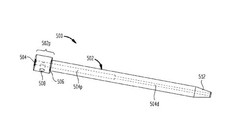
depth stop of FIG. 10, and the guide tube of FIG. 13;
[0019] FIG. 16 is another perspective view of the tip protector of FIG. 3, the
microcatheter of
FIG. 1, the depth stop of FIG. 10, and the guide tube of FIG. 13;
[0020] FIG. 17 is a perspective view of another exemplary stereotactic system;
[0021] FIG. 18 is a perspective view of the tip protector of FIG. 3, the
microcatheter of FIG. 1, the
depth stop of FIG. 10, the guide tube of FIG. 13, an exemplary guide stop
adapter, and an
exemplary guide block adapter;
[0022] FIG. 19 is another perspective view of the tip protector of FIG. 3, the
microcatheter of FIG.
1, the depth stop of FIG. 10, the guide tube of FIG. 13, and the guide stop
and guide block adapters
of FIG. 18; and
[0023] FIG. 20 is a perspective view of the tip protector of FIG. 3, the
microcatheter of FIG. 1, the
depth stop of FIG. 10, the guide tube of FIG. 13, the guide stop and guide
block adapters of FIG.
18, and an exemplary stereotactic system.
BACKGROUND
[0024] In convection-enhanced delivery (CED), drugs are infused locally into
tissue through a
needle, cannula, or microcatheter inserted into the tissue. Transport of the
infused material is
dominated by convection, which enhances drug penetration into the target
tissue compared with
2
CA 2915505 2020-11-30
diffusion-mediated delivery or systemic delivery.
[0025] The devices used to perform CED, as well as devices used in several
other fields, can
include a very small, thin tip (e.g., a microfabricated tip). For example, as
shown in FIG. 1, a
microcatheter 100 can include a catheter body 102 with a microfabricated tip
104 at the distal
end thereof. The tip can be damaged or broken during handling and/or during a
surgical
procedure. For example, the tip can either break during handling as a user
hits the catheter tip
against an object, or the surgeon may break the tip while inserting it in the
brain through a
stereotactic system. Stereotactic systems generally have a lumen with a small
inside diameter
(ID) to snugly fit the catheter. For example, as shown in FIG. 2, an exemplary
stereotactic
system 200 has a small-diameter central lumen 202 extending therethrough. The
surgeon is
required to "aim" the small catheter into the tight lumen to get the catheter
loaded into the
stereotactic system. Catheters with small tips may get damaged as the surgeon
may hit the tip
against the stereotactic system while manually trying to align the catheter to
the small lumen. In
addition, stereotactic systems are generally sized for larger instruments and
cannot adequately
support and protect catheters with small diameters or small tips.
[0026] A need exists for methods and devices for protecting catheter tips and
stereotactic fixtures for
microcatheters.
SUMMARY
[0027] Methods and devices are disclosed herein that generally provide
protection for devices
(e.g., microcatheters) having small tips. Methods and devices are also
disclosed herein that
generally facilitate use of commercially-available stereotactic systems with
devices (e.g.,
microcatheters) having small tips.
[0028] In some embodiments, a tip protection device includes an elongate body
having a central
lumen extending longitudinally therethrough, the lumen being sized and
configured to slidably
receive a catheter, and a locking mechanism configured to selectively maintain
the elongate body in a
fixed longitudinal position relative to a catheter inserted through the
central lumen.
[0029] The locking mechanism can include a screw. The elongate body can
include an increased-
diameter portion configured to act as a depth stop when the elongate body is
inserted through a
lumen of a stereotactic system. The elongate body can be formed from at least
one of silastic,
poly-urethane, poly-ester, PTFE, E-PTFE, stainless steel, polycarbonate, PVC,
Delrin,
aluminum, PEEK, plastic, metal, and titanium. The elongate body can be
fabricated using at least
one of extrusion, molding, and machining. The elongate body can include a
sharpened distal tip.
3
CA 2915505 2020-11-30
The distal tip can be separable from the elongate body along a perforated snap
portion. The
elongate body can include a distal cylindrical portion having a first diameter
and a proximal
cylindrical portion having a second diameter that is greater than the first
diameter. The central
lumen can have a diameter of about 0.5 mm to about 4.0 mm.
[0030] In some embodiments, a system includes a tip protection device (e.g.,
of the type described
above) and a depth stop comprising a cylindrical body portion having a central
lumen extending
longitudinally therethrough and a locking mechanism configured to selectively
engage a catheter
inserted through the cylindrical body portion.
[0031] In some embodiments, a system includes a tip protection device (e.g.,
of the type described
above) and a guide tube that includes an elongate body having a central lumen
extending
longitudinally therethrough, the central lumen including a proximal portion
having a first diameter
and a distal portion having a second diameter that is less than the first
diameter, the proximal
portion being sized to receive a reduced diameter distal portion of the tip
protection device and the
distal portion being sized to receive at least a portion of a catheter
inserted through the tip
protection device.
[0032] The elongate body of the guide tube can include a proximal portion
having an outside
diameter which is greater than an outside diameter of a distal portion of the
elongate body of the
guide tube. A distal end of the guide tube can be tapered. The system can
include a guide stop
adapter comprising a cylindrical disc having an inside diameter sized to
receive the distal portion
of the guide tube therethrough and an outside diameter sized to fit within a
guide stop of a
stereotactic system, and a guide block adapter comprising a cylindrical sleeve
having an inside
diameter sized to receive the distal portion of the guide tube therethrough
and an outside
diameter sized to fit within a guide block of a stereotactic system. The guide
tube can have a
length sufficient to span a distance between the guide block of the
stereotactic system and a skull
of a patient to which the stereotactic system is registered.
[0033] In some embodiments, a method of inserting a catheter into a patient
includes registering
a stereotactic system to the patient, inserting a catheter having a tip
protection device disposed
over a distal tip thereof into a working channel of the stereotactic system
until a depth stop on
the tip protection device prevents further insertion, releasing a locking
mechanism of the tip
protection device and advancing the catheter distally into the patient, and
engaging a locking
mechanism of the stereotactic system with the tip protection device, thereby
engaging the tip
protection device with the catheter to maintain a fixed longitudinal position
between the catheter
and the stereotactic device.
4
CA 2915505 2020-11-30
[0034] The method can include delivering a therapeutic agent through the
catheter using
convection-enhanced delivery. The method can include, before said releasing
and engaging,
piercing the dura of the patient with a sharpened distal tip of the tip
protection device, removing the
tip protection device from the stereotactic frame, snapping off the sharpened
distal tip of the tip
protection device, and reinserting the tip protection device through the
stereotactic frame. The
method can include inserting the tip protection device through a central lumen
of a guide tube
mounted in the stereotactic system such that a distal end of the tip
protection device is received
within a proximal portion of the central lumen of the guide tube. Advancing
the catheter can
include advancing a distal tip of the catheter through a distal portion of the
central lumen of the
guide tube, the distal portion of the central lumen of the guide tube having a
diameter that is less
than a diameter of the proximal portion of the central lumen of the guide
tube, such that at least
a portion of the catheter is disposed within the distal portion of the central
lumen of the guide
tube. The method can include inserting the guide tube through a guide stop
adapter and a guide
block adapter mounted in the stereotactic system.
Accordingly, in one aspect the present invention resides in a system,
comprising:
a tip protection device, comprising: an elongate body having a central lumen
extending
longitudinally therethrough, the lumen being sized and configured to slidably
receive a catheter;
and a locking mechanism configured to selectively maintain the elongate body
in a fixed
longitudinal position relative to [[a]]the catheter inserted through the
central lumen; and a guide
tube comprising: an elongate body having a central lumen extending
longitudinally therethrough,
the central lumen including a proximal portion having a first diameter and a
distal portion having a
second diameter that is less than the first diameter, the proximal portion
being sized to receive a
reduced diameter distal portion of the tip protection device and the distal
portion being sized to
receive at least a portion of the catheter inserted through the tip protection
device; and a set screw
received in a lateral opening formed in a proximal end of the guide tube, the
set screw locking the
tip protection device in place within the central lumen of the elongate body
of the guide tube.
[0035] The present invention further provides devices, systems, and methods as
additionally
described herein.
CA 2915505 2020-11-30
CA 02915505 2015-12-15
WO 2014/204954 PCT/US2014/042726
DETAILED DESCRIPTION
[0036] Methods and devices are disclosed herein that generally provide
protection for devices
(e.g., microcatheters) having small tips. Methods and devices are also
disclosed herein that
generally facilitate use of commercially-available stereotactic systems with
devices (e.g.,
microcatheters) having small tips.
[0037] Certain exemplary embodiments will now be described to provide an
overall
understanding of the principles of the structure, function, manufacture, and
use of the methods,
systems, and devices disclosed herein. One or more examples of these
embodiments are
illustrated in the accompanying drawings. Those skilled in the art will
understand that the
methods, systems, and devices specifically described herein and illustrated in
the accompanying
drawings are non-limiting exemplary embodiments and that the scope of the
present invention is
defined solely by the claims. The features illustrated or described in
connection with one
exemplary embodiment may be combined with the features of other embodiments.
Such
modifications and variations are intended to be included within the scope of
the present
invention.
[0038] In some embodiments, a tip protector is provided in the form of a
sleeve. The sleeve can
be formed by cutting a length of tubing or using extrusion, molding, and/or
machining processes.
The sleeve can include a central lumen extending longitudinally therethrough,
defined by a
relatively thin wall. The sleeve can be slid over the catheter (or similar
small-tip device) to
protect the catheter tip from breakage or damage during handling or use. The
tip protector can
be configured to sit over the catheter or other device such that it covers and
protects the micro-
tip. The tip protector can be secured on the catheter using a set-screw or a
snap feature, or other
feature that can easily be un-deployed to slide the catheter through the
sleeve as needed. The tip
protector can be packaged and shipped with the catheter (e.g., with the
protector pre-installed
over the tip of the catheter).
[0039] In use, the surgeon/user can align the catheter to the stereotactic
system using the sleeve
as a reference. Once aligned, the tip protector and catheter can be slid
inside the stereotactic
system (the tip protector can be sized to fit existing systems). Once inside
the stereotactic
system, the user can loosen the set-screw on the tip protector to slide the
catheter further into the
6
brain or other tissue. The proximal end of the tip protector can have a large
outside diameter (OD)
stop or collar that does not allow it to slide inside the stereotactic system
as the catheter is being
inserted into the brain. Once the catheter is inserted into the brain, the
stereotactic system set-screw
can be tightened over the tip-protector sleeve (due to the thin wall) onto the
catheter to fix it in place
and prevent the catheter from sliding. The tip protector can be MRI compatible
so that it does not
interfere with MR imaging.
[0040] FIG. 3 illustrates an exemplary embodiment of a tip protector 300
having a set screw and
a large diameter stop portion. As shown, the tip protector 300 includes an
elongate sleeve 302.
The distal portion 320d of the sleeve 302 has an outside diameter which is
less than the outside
diameter of the proximal portion 302p of the sleeve. The outside diameter of
the sleeve 302 can
be curved, ramped, stepped, or tapered at the junction of the proximal and
distal portions to
provide a transition or shoulder 304. This transition 304 can act as a
shoulder or stop surface to
limit the degree to which the tip protector 300 can be advanced distally
through a cylindrical
opening, such as the opening of a stereotactic system. A central cylindrical
lumen 306 extends
through the tip protector 300 from a proximal end of the sleeve 302 to a
distal end of the sleeve.
The lumen 306 is sized and configured to receive at least a portion of a
catheter therethrough.
The tip protector 300 also includes a set screw 308 threadably mounted in a
channel 310 which
extends perpendicular to the central lumen 306. Rotation of the set screw 308
in a first direction
can be effective to advance the set screw within the channel 310 such that it
extends into the
central lumen 306 and engages a catheter or other instrument inserted
therethrough. Rotation of
the set screw 308 in a second, opposite direction can be effective to withdraw
the set screw
within the channel 310 such that it does not extend into the central lumen 306
and does not
engage a catheter or other instrument inserted therethrough.
[0041] The tip protector 300 is shown in FIG. 4 with an exemplary embodiment
of a
microcatheter 100 for convection-enhanced delivery. It will be appreciated
that any of a variety
of microcatheters or other instruments can be used with the tip protector.
Exemplary
microcatheter devices are disclosed in the following references: U.S.
Publication No.
2013/0035560 entitled MULTI-DIRECTIONAL MICROFLUIDIC DRUG DELIVERY
DEVICE; U.S. Publication No. 2013/0035574 entitled MICROFLUIDIC DRUG DELIVERY
DEVICES WITH VENTURI
7
CA 2915505 2020-11-30
EFFECT; U.S. Publication No. 2013/0035660 entitled MULTIDIRECTIONAL
MICROFLUIDIC DRUG DELIVERY DEVICES WITH CONFORMABLE BALLOONS; U.S.
Application No. 14/132,762 entitled SYSTEMS AND METHODS FOR REDUCING OR
PREVENTING BACKFLOW IN A DELIVERY SYSTEM; U.S. Publication No.
2010/0098767 entitled CONVECTION ENHANCED DELIVERY APPARATUS, METHOD,
AND APPLICATION; and U. S . Publication No. 2013/0046230 entitled ULTRASOUND-
ASSISTED CONVECTION ENHANCED DELIVERY OF COMPOUNDS IN VIVO WITH A
TRANSDUCER CANNULA ASSEMBLY.
[0042] As shown in FIG. 5, the microcatheter 100 can be inserted through the
central lumen 306
of the tip protector 300. The set screw 308 can be tightened to secure the tip
protector 300 to the
microcatheter 100 and prevent longitudinal translation of the tip protector
relative to the
microcatheter. The microcatheter 100 can also be positioned such that the tip
104 of the
microcatheter protrudes from a distal end of the tip protector 300, as shown
in FIG. 6. This
relative positioning of the tip protector 300 and the microcatheter 100 would
typically be used
only after the microcatheter is inserted into the stereotactic system,
although the user may wish to
slide the tip 104 out of the tip protector before insertion to confirm fluid
flow during priming,
etc., and then retract the tip back into the tip protector before inserting
the catheter through the
stereotactic system.
[0043] The tip protector can be used with any of a variety of stereotactic
systems. For example,
as shown in FIGS. 7-9, the tip protector 300 can be used with a stereotactic
system 200 of the
type available from MEDTRONIC, INC. under the NAVIGUSTM brand. The illustrated
stereotactic system 200 includes a base 204 with a locking ring 206 and a stem
208 that can be
positioned at various angles with respect to the base. The stem 208 includes a
set screw 210 to
secure a device inserted through an inner lumen 202 of the stem. In use, the
base 204 is installed
over a portion of the patient (e.g., a burr hole formed in the patient's
skull).
[0044] As shown in FIG. 7, the microcatheter 100 can be aligned to the small
hole 202 in the stem 208
without damaging the catheter tip by using the tip protector 300 as a visual
and contact reference. The
outside diameter of the distal portion 302d of the tip protector 300 can be
sized to substantially match
the inside diameter of the central lumen 202 of the stem 208 such that the tip
protector fits snugly
within the stereotactic system 200, as shown in FIG. 8. As shown in FIG. 9,
8
CA 2915505 2020-11-30
CA 02915505 2015-12-15
WO 2014/204954 PCT/US2014/042726
the tip protector 300 can be advanced distally within the stem 208 until the
shoulder portion 304
of the tip protector engages the proximal end of the stem and prevents further
insertion. The
large diameter stop portion 302p on the tip protector 300 can thus prevent the
tip protector from
being advanced too far through the stereotactic system 200. The distal portion
302d of the tip
protector 300 can have a length that substantially corresponds to the length
of the stem 208, such
that the distal end of the tip protector is aligned with the distal end of the
stereotactic system 200
when the tip protector is inserted up to the shoulder portion 304.
[0045] Once the tip protector 300 is inserted through the stem 208, the set
screw 308 of the tip
protector can be loosened to allow the microcatheter 100 to be translated
longitudinally relative
to the tip protector and the stem, such that the catheter tip can be advanced
distally into the
patient or retracted proximally from the patient. The set screw 210 on the
stem 208 can be
tightened over the tip protector 300 to secure the catheter 100 and the tip
protector with respect
to the stem.
[0046] The terminal distal end of the tip protector 300 can also be made to be
sharp and, when
the tip protector is fully-advanced into the stereotactic system 200, the
distal tip of the tip
protector can extend into the skull and past the dura to ensure the dura and
corresponding
anatomies are pierced and will not interfere with the catheter micro-tip 104
during insertion. For
example, the distal tip of the tip protector 300 can be pointed or otherwise
sharpened and can
extend a few millimeters beyond the skull when inserted through the
stereotactic system 200.
The length of the tip protector 300 can thus be selected based on the
stereotactic system with
which it will be used to achieve the desired degree of protrusion. In an
exemplary method of
use, the catheter 100 and that elongated, sharp-tipped protector 300 can be
inserted through the
stereotactic system 200 such that the distal tip of the tip protector extends
through the skull and a
few millimeters past the dura, thereby opening, tearing, and/or piercing the
dura. The catheter
100 and the tip protector 300 can then be removed and the sharp tip of the tip
protector can be
broken or snapped off (e.g., along a perforated snap section or frangible
portion) to expose the
lumen 306 of the tip protector. The tip protector 300 and the catheter 100 can
then be re-inserted
and used as described above.
[0047] As shown in FIG. 10, a depth stop 312 can be included for setting the
desired insertion
depth of the microcatheter 100 and preventing over-insertion. The illustrated
depth stop 312
9
CA 02915505 2015-12-15
WO 2014/204954 PCT/US2014/042726
includes a collar 314 that can be longitudinally slidable with respect to the
catheter 100 and can
include a thumb screw 316 for engaging the catheter to secure the collar in a
fixed longitudinal
position with respect thereto. In particular, the set screw 316 can be
selectively positioned such
that a tip of the set screw extends into a central lumen 318 of the collar 314
to engage the
microcatheter 100 disposed therein. As the microcatheter 100 is advanced
distally through the
tip protector 300, the collar 314 eventually contacts the proximal end of the
tip protector,
preventing further insertion of the catheter. The depth stop 312 can thus be
slid along the
catheter 100 and locked in place to set the maximum insertion depth. The
catheter 100 can also
include depth markings on the catheter body 102 to help a user place the depth
stop 312 at the
desired calculated depth.
[0048] In some embodiments, the tip protector can have a standard length to
allow easy depth
registration between the tip protector, the catheter, and the stereotactic
system. In some
embodiments, the distal portion of the tip protector is approximately 5 cm in
length and the
proximal, increased-diameter portion of the tip protector is approximately 1
cm in length such
that the tip protector has an overall length of approximately 6 cm.
Accordingly, a catheter with
marked depth graduations on its exterior sidewall can be advanced into the tip
protector to the 6
cm marking, indicating that the distal end of the catheter is aligned (i.e.,
not protruding or
recessed) with the distal end of the tip protector. Similarly, the tip
protector can be fully-
advanced into a stereotactic system having a 5 cm stem length, such that the
distal end of the tip
protector is aligned (i.e., not protruding or recessed) with the distal end of
the stereotactic
system.
[0049] In some embodiments, the central lumen of the tip protector can have an
inside diameter
that corresponds to (e.g., is substantially equal to or slightly greater than)
the outside diameter of
the catheter. For example, the central lumen of the tip protector can have a
diameter of about 0.5
mm to about 4.0 mm. In some embodiments, the central lumen of the tip
protector can have a
diameter of about 1.5 mm Tn some embodiments, the central lumen of the tip
protector can have
a diameter of about 3.0 mm.
[0050] While an exemplary microcatheter 100 and an exemplary stereotactic
system 200 are
shown and described above, it will be appreciated that the tip protector 300
can be sized or
otherwise configured to work with any of a variety of catheters or other small-
tipped devices,
and can likewise be sized or otherwise configured to work with any of a
variety of stereotactic
systems, stems, collets, sleeves, frames, etc. In addition, one or more
fixtures, adapters, guides, or
other accessories can be included to facilitate use of the tip protector
and/or a microcatheter with a
particular stereotactic system.
[0051] Exemplary stereotactic systems include the NAVIGUSTm system available
from
MEDTRONIC, INC. and the VARIOGUIDETm system available from BRAINLABlm. Both of
these
systems are "frameless," meaning they are mounted directly or close to the
patient's head, and do not
need the functional "frame" per conventional stereotactic procedures.
[0052] As shown above and in FIG. 11, the tip protector 300 can be sized to be
received within the
inner lumen of the NAVIGUSTm system 200. For example, the distal portion 302d
of the tip
protector 300 can have a length that is equal to the length of the stem 208,
such that when the tip
protector is inserted up to the proximal, increased-diameter portion 302p, the
distal end of the tip
protector is aligned with the distal end or center of the pivoting stem, which
typically serves as the
depth reference point in the system 200. This can advantageously allow for
simple depth
registration between the catheter 100, the tip protector 300, and the system
200. In some
embodiments, the distal portion 302d of the tip protector 300 has a length of
approximately 5 cm.
[0053] Similarly, as shown in FIG. 12, the length of the tip protector 300 can
be selected to
correspond with the diameter of the circular guide block 400 of the
VARIOGUIDETm system,
thereby facilitating depth registration between the catheter 100, the tip
protector 300, and the
system.
[0054] In some embodiments, a guide tube can be provided to facilitate
coupling of the tip
protector 300 and/or the catheter 100 to the stereotactic system. FIG. 13
illustrates an exemplary
embodiment of a guide tube 500. As shown, the guide tube 500 has an elongate
body 502 with a
central lumen 504 extending longitudinally therethrough. The inside diameter
of the central
lumen 504 is stepped, such that the lumen includes an increased-diameter
proximal portion 504p
sized to receive the distal end 302d of the tip protector 300 and a decreased-
diameter distal
portion 504d sized to snugly receive a portion of the catheter 100 that
protrudes from the distal
end of the tip protector. The guide tube 500 also has a proximal end 502p with
an enlarged
outside diameter such that a shoulder 506 is defined on the exterior of the
guide tube. In use, the
11
CA 2915505 2020-11-30
guide tube 500 can be inserted distally through the guide block of a
stereotactic system until the
shoulder 506 engages the guide block. The tip protector 300 can be inserted
into the central
lumen 504 of the guide tube 500 such that the tip protector is supported and
stabilized in the
stereotactic system. A lateral opening 508 can be included in the proximal end
of the guide tube
500 to receive a set screw 510 for locking the tip protector 300 in place
within the central lumen
504. The enlarged proximal end 502p of the guide tube 500 can have a standard
length (e.g., 1
cm) to aid in depth registration. The guide tube 500 can also include a
tapered distal tip 512 for
easy insertion of the guide tube into the guide block of the stereotactic
system.
[0055] FIG. 14 illustrates an exemplary frame-based stereotactic system ¨ the
CRW frame
available from INTEGRA LIFESCIENCESTm. As shown, the guide tube 500 can be
sized to fit the
existing guide block 602 of the frame 600 and help guide the catheter 100 from
the guide block to
the top of the skull 604. For example, the guide tube 500 can have an outside
diameter of 0.25" to
correspond with the inside diameter of the frame's guide block 602. The guide
tube 500 can thus
allow the frame 600 to be used with microcatheters 100 that would not
otherwise fit in the guide
block 602. In some embodiments, a kit including a plurality of guide tubes
having different lengths
can be provided. Accordingly, as the arc of the frame 600 is moved towards or
away from the
patient's skull 604 depending on target depth, a guide tube having an
appropriate length can be
selected such that the guide tube supports the full length or a significant
portion of the full length
of the microcatheter 100 extending between the guide block 602 and the skull
604.
[0056] FIG. 15 is a schematic illustration of a microcatheter 100 coupled to a
tip protector 300 and
depth stop 312 and aligned with the guide tube 500. FIG. 16 is a schematic
illustration of the
microcatheter 100 and tip protector 300 inserted through the guide tube 500.
As shown, the tip
protector 300 can be advanced until the enlarged proximal end 302p of the tip
protector engages the
proximal end surface of the guide tube 500.
[0057] FIG. 17 illustrates another exemplary frame-based stereotactic system ¨
the LEKSELLTm
frame available from ELEKTATm. As shown, the system 700 includes an upper
guide stop 702
mounted to the arc 704 of the frame. The system 700 also includes a lower
guide block 706
mounted to an arm 708 that extends down from the arc 704 towards the patient's
skull 710. In some
embodiments, a guide stop adapter 802 and a guide block adapter 804 can be
provided to
12
CA 2915505 2020-11-30
facilitate coupling of the guide tube 500, tip protector 300, and/or the
catheter 100 to the
LEKSELLTm system 700 or to other similar systems.
[0058] FIG. 18 illustrates a microcatheter 100 (with a depth stop 312 and a
tip protector 300), a guide
tube 500, a guide stop adapter 802, and a guide block adapter 804. These
components are illustrated
in an assembled configuration in FIG. 19 and installed in the LEKSELLTm frame
700 in FIG. 20.
[0059] As shown, the guide stop adapter 802 can be a cylindrical disc having
an inside diameter
sized to receive the guide tube 500 and an outside diameter sized to fit
within the guide stop 702 of
the stereotactic system 700. The guide stop adapter 802 can include an
enlarged proximal end 802p
that defines an exterior shoulder 806.
[0060] The guide block adapter 804 can be a cylindrical sleeve having an
inside diameter sized
to receive the guide tube 500 and an outside diameter sized to fit within the
guide block 706 of
the stereotactic system 700. The guide block adapter 804 can include an
enlarged proximal end
804p that defines an exterior shoulder 808. Lateral openings 810, 812 can be
formed in the guide
stop adapter 802 and/or the guide block adapter 804 to receive set screws 814,
816 for locking
the guide tube 500 in position. In use, the guide stop adapter 802 and the
guide block adapter 804
can be fitted to the guide stop 702 and guide block 706, respectively, of the
stereotactic frame
700 and adjusted to the desired heights. The guide tube 500 can then be
inserted through the
adapters 802, 804, and can be secured in a fixed longitudinal position by
tightening the set
screws 814, 816 of the guide stop adapter 802 and the guide block adapter 804.
The
microcatheter 100 and attached tip protector 300 can then be inserted through
the guide tube 500.
The set screw of the guide tube 500 can be tightened to secure the tip
protector 300 to the guide
tube, before or after advancing the microcatheter 100 relative to the tip
protector to the desired
depth. The set screw 308 of the tip protector 300 can also be tightened to
secure the
microcatheter 100 in a fixed longitudinal position relative to the tip
protector.
[0061] It will be appreciated that similar adapters can be made to fit other
frames to facilitate
stereotactic use of the tip protectors and microcatheters disclosed herein.
The systems and
methods disclosed herein can facilitate precision-targeted drug delivery
(e.g., via convection-
enhanced delivery) using a stereotactic system and a microcatheter. In an
exemplary
13
CA 2915505 2020-11-30
CA 02915505 2015-12-15
WO 2014/204954 PCT/US2014/042726
embodiment, a stereotactic system is registered to a patient, for example
using MR images. A
microcatheter and associated tip protector can be coupled to the stereotactic
system using one or
more guide tubes, guide block adapters, and/or guide stop adapters as
disclosed herein and aimed
towards a target site in the patient. The microcatheter can then be advanced
into the patient
under stereotactic guidance until one or more fluid outlet ports of the
microcatheter are
positioned at the target site. Drug-containing fluid can then be infused under
positive pressure to
deliver the drug through the catheter to the target site via convection-
enhanced delivery.
[0062] The tip protectors, depth stops, fixtures, adapters, guides, and other
components or
devices disclosed herein can be manufactured or produced using any of a
variety of techniques,
including extrusion, molding, machining, and combinations thereof. The tip
protectors, depth
stops, fixtures, adapters, guides, and other components or devices disclosed
herein can be formed
from a variety of materials, including silastic, poly-urethane, poly-ester,
PTFE, E-PTFE,
stainless steel, titanium, polycarbonate, PVC, Delrin, aluminum, PEEK,
plastic, metal, and
combinations thereof.
[0063] Although the invention has been described by reference to specific
embodiments, it
should be understood that numerous changes may be made within the spirit and
scope of the
inventive concepts described. Accordingly, it is intended that the invention
not be limited to the
described embodiments, but that it have the full scope defined by the language
of the following
claims.
14