Note: Descriptions are shown in the official language in which they were submitted.
CA 2915555 2015-12-16
PCT/IB 2014/001 244 - 21-08-201
cõ.4.24.A. urn
e..ot-solzg
= 1
Method for energy saving.
The present invention relates to a method for energy saving
applied in industrial processes.
More specifically, the invention is intended for the
recovery of energy by coupling a heat-requiring industrial
process to a cold-requiring industrial process.
It is known that many industrial processes require heat. An
example is the process whereby French fried potatoes are
fried in vegetable oil at 180 C.
It is also known that many industrial processes require
cold. An example is the freezing of pre-fried French fried
potatoes at a temperature of -33 C.
Traditionally a lot of energy is lost in a heat-requiring
industrial process due to cooling and the emission of heat
to the atmosphere. In the process in which potatoes are
fried as French fried potatoes or potato crisps for
example, when frying, water present in the potatoes
evaporates, and the steam and oil vapour formed is cooled
in the air, so that the heat energy therein is emitted to
the atmosphere.
In order to entirely or partially utilise this heat energy,
it is known to exchange the heat of these vapours with
another medium such that the water and oil in the vapour
condenses. It is also known that when the other medium is
AMENDED SHEET
CA 2915555 2015-12-16
PCT/IB 2014/001 244 - 21-08-201
2
water, hot water can hereby be produced. If the other
medium has a binary composition, consisting of water and
ammonia, a complete or partial phase transition can occur
which is then brought to a higher pressure by means of a
compressor.
The compressed binary medium is then guided through a heat
exchanger that acts as a heating installation for the
cooking oil still to be heated up, i.e. cooled cooking oil
from the fryer and new cooking oil that makes up for the
loss of cooking oil, whereby a proportion of the heat from
the compressed binary medium is emitted to the cooled or
new cooking oil such that this binary medium entirely or
partially condenses.
Then the entirely or partially condensed binary medium is
expanded in an expander whereby electrical energy is
generated. The flow of fluid that leaves the expander is a
flow that comprises two phases (liquid and vapour) that is
traditionally fed back to the condenser where the vapour is
condensed into liquid and whereby the energy-recovery
circuit is closed.
Also in an industrial process whereby refrigeration to
deepfreeze temperatures (approx. -30 C) is required, part
of the energy that must be supplied to obtain the
refrigeration is not recovered by means of an expander that
generates electricity, but by means of a reducing valve
that reduces the pressure in order to develop cold
according to the Joule-Thomson effect. Using a condenser
the heat energy developed by the compressor is emitted to
AMENDED SHEET
CA 2915555 2015-12-16
PCT/IB 2014/001 244 - 21-08-201
3
the atmosphere, in heat exchangers with which the heated
and compressed coolant gas is cooled.
The refrigeration is obtained by compressing a suitable
coolant gas, generally ammonia, after which the compressed
and condensed coolant gas is expanded in a reducing valve
whereby the temperature of the coolant gas falls sharply
and is further guided to a phase separator that separates
the gas phase from the cold liquid phase (approx. -30 C)
which can be used for all kinds of refrigerating
installations such as a freezer line, a frozen storage zone
and other cold stores.
The heated coolant gas that results after refrigeration can
now be compressed again, partly with the electricity
generated, in order to be expanded as a compressed coolant
gas in an expander whereby the coolant gas circuit is
closed.
Extra energy saving is possible by transferring heat from a
first industrial process to which heat has been supplied to
another industrial process whereby cold must be produced.
This is possible by converting the low value residual heat
of the first industrial process into high value cold for
the second industrial process that requires cold.
In the aforementioned example the process for frying
potatoes to prepare French fried potatoes is coupled to the
process for freezing these French fried potatoes and
putting them on the market as a frozen product, resulting
in an extra energy saving.
AMENDED SHEET
CA 2915555 2015-12-16
PCT/IB 2014/001 244 - 21-08-201
4
In order to measure the efficiency of an industrial energy-
saving process, an energy coefficient of performance (COP)
is frequently used that reflects the ratio of the recovered
energy with respect to the energy that must be supplied for
the recovery thereof. Only when this COP is greater than
two and a half (2.5) is the recovery process economically
worthwhile in view of the KWe and KWth price ratio.
A number of systems for heat recovery from a heat-requiring
process are already known.
W02009/045196 and EP 2514931 describe heat recovery from a
heat source by means of cascaded Rankine cycles with
organic energy carriers that are not compressed by
compressors.
W02013/035822 also describes heat recovery by means of
cascaded Rankine cycles, each with a pure substance as an
energy carrier and without a compressor.
CN202562132 describes the coupling of a heat-requiring
process (swimming pool) to a cold-requiring process (ice
rink) and uses a compressor for a gaseous energy carrier.
0S4573321 recovers heat from a heat source by means of a
coolant composed of a component with high volatility and
components with low volatility. The method does not use a
compressor but countercurrent heat exchangers.
AMENDED SHEET
5
W02011/081666 recovers heat with a Rankine cycle that uses
ammonia as an energy carrier and uses a compressor for
compressing CO2 gas whereby heat is exchanged between CO2
and ammonia in heat exchangers. A binary energy carrier is
not used.
EP 1.553.264 A2 describes an improved Rankine cycle for a
steam pbwer plant. Steam is injected directly and the
resulting two-phase flow is pressurized by multiphase
pumps. It is clear from figures 3 and 4 that the Rankine
cycle does not avoid the supercritical condition, but shows
an important spike in the area where superheated steam is
produced which is then used to drive a turbine. The energy
carrier is not a binary fluid.
GB 2.034.012 A describes a method of producing process
steam by feeding a two-phase mixture of water and steam
into the inlet of a helical screw compressor and by
evaporating the water component of the mixture. A fine
spray of water is injected at the entrance of the
compressor. It is clear from figure 2 that the
supercritical condition of superheated steam is not avoided
in this system, and that the fluid used is not a binary
fluid.
The purpose of the present invention is to enable extra
energy saving by providing a method for coupling a first
heat-requiring industrial process to a second cold-
requiring industrial process, whereby a first circuit for
energy recovery from the first industrial process transfers
heat to a second circuit for cold production for the second
CA 2915555 2017-10-16
6
cold-requiring industrial process, whereby in the first
circuit for energy recovery the first energy carrier is a
binary mixture of water and ammonia which has two phases and
is compressed by a compressor specifically suitable for
compressing a two-phase fluid such as a compressor with a
Lysholm rotor or equipped with vanes or a variant developed
to this end, whereby all or part of the liquid phase
evaporates as a result of compression such that overheating
does not occur and such that less working energy must be
supplied, and such that the total energy coefficient of
performance or COP of the coupled processes is increased
with respect to the total COP of non-coupled processes.
An advantage of the use of such a compressor suitable for a
two-phase fluid is that it consumes less energy to compress
a two-phase fluid to a certain temperature and pressure
than to compress an exclusively gaseous fluid to this
temperature and pressure. In a two-phase fluid, all or part
of the liquid phase evaporates as a result of compression
such that overheating does not occur and such that less
working energy must be supplied.
Preferably the method whereby the circuit for energy
recovery from the first industrial process is coupled to
the circuit for cold production of the second industrial
process, whereby the heat of the first energy carrier in
the first circuit, that remains after expanding the energy
carrier in an expander for electricity generation, is
additionally utilised to heat the second energy carrier of
the second industrial process by means of a heat exchanger
between the first circuit for energy recovery and the
CA 2915555 2017-10-16
7
second circuit for cold production that additionally heats
the energy carrier of the second process before it is
expanded in the expander of the second circuit for
electricity and cold production.
An advantage of this coupling of the two circuits is that
the total energy saving for the coupled circuits is greater
than the sum of the energy recovery of each circuit when
they are not coupled.
Preferably the energy carriers of the first and second
circuit for energy saving in this method for energy
recovery differ from one another. For example the second
energy carrier of the second circuit for energy saving can
have a lower boiling point than first the energy carrier of
the first circuit for energy recovery, such that it is
suitable for use in refrigerating installations.
Part of the heat that remains after expanding the energy
carrier in the first expander for electricity generation is
recovered by this coupling as electrical energy in the
second expander.
Preferably in this method for energy recovery a proportion
of the heat that is generated by a first compressor in the
first energy carrier of the first circuit for energy
recovery is used to heat a process fluid in the form of a
liquid or gas in the first industrial process, and this by
means of a heat exchanger between the first circuit for
energy recovery and a pipe for the supply of the process
fluid to the process vessel of the first industrial
CA 2915555 2017-10-16
8
process, where it is brought to the desired temperature for
a production stage in the first industrial process.
An advantage of this utilisation of recovered heat for use
in a production stage in the first industrial process is
that less energy needs to be supplied from the outside,
which leads to an energy saving in the first industrial
process.
The first energy carrier of the first circuit for energy
saving being water and ammonia is a two phase fluid i.e.
consists of a mixture of a liquid phase and a vapour or gas
phase.
An advantage of such an energy carrier is that it can be
brought to the liquid or gas state according to desire by
controlling the pressure and temperature.
The second energy carrier of the second circuit for cold
production in this method for energy recovery consists of
ammonia, whereby an entire or partial phase transition
between the gas phase and liquid phase occurs that is then
brought to a higher pressure by means of a compressor.
At atmospheric pressure ammonia has a boiling point of
-33 C, such that a low temperature can be obtained due to
the expansion of the second energy carrier.
CA 2915555 2017-10-16
9
An advantage of ammonia as an energy carrier is that its
low boiling point enables the energy carrier to be utilized
in liquid form for industrial refrigeration processes such
as the freezing of foodstuffs or other substances.
Preferably the second circuit for cold production is
equipped with an electric pump with which the second energy
carrier of the second circuit for cold production is
brought to a higher pressure before being expanded in a
second expander of the second circuit for cold production.
An advantage of this electric pump is that it brings the
second energy carrier to a higher pressure, such that more
energy can be released by expansion in the second expander
and that it can be partially driven by recovered
electricity originating from one or both expanders of the
coupled industrial processes.
Preferably the second circuit for cold production comprises
a separator, between the second expander for expanding and
a compressor for compressing the second energy carrier, for
separating the liquid phase from the gas phase in the
second energy carrier, followed by one or more
refrigerating installations for one or more production
stages in the second industrial process that utilises the
liquid phase far cooling.
An advantage of this separator is that the liquid phase of
the second energy carrier can be guided to the industrial
refrigerating installations that are thereby cooled, while
CA 2915555 2017-10-16
10
the gas phase can be guided to a compressor to increase the
pressure in the gas phase.
Preferably the second energy carrier of the second circuit
for cold production, after compression in a compressor to a
pressure whereby it becomes liquid again due to ambient
cooling, is further guided to a heat exchanger in which as
an option surplus heat can be transferred from the second
energy carrier to another process liquid that is used
elsewhere in the coupled production processes, in this case
demineralised water that is converted to steam.
An advantage of this heat exchanger is that surplus heat
can be utilized directly in the industrial process such
that less external energy needs to be supplied to reach the
required temperature.
Preferably the heat exchanger for the surplus heat of the
second energy carrier is connected by means of a tap to a
separator in which saturated steam and saturated
demineralised water are separated from one another at a
pressure of 400 kPa.
An advantage of this separator is that steam can be
produced for industrial use.
Preferably the condensed part of the separator is fed back
to the supply flow of this heat exchanger, as well as the
condensate from the consumed steam.
CA 2915555 2017-10-16
11
The water originating from another separator, with which
the water vapour originating from the first production
process, in this case the water that evaporates from the
potatoes due to the frying process, is recovered, and after
filtration is available for industrial use, which reduces
the need for potable water in the first industrial
production process.
The second energy carrier of the second circuit for cooling
is now further guided in gas form to a condenser in which
the gas is condensed into a liquid and further guided to a
pump that further drives the energy carrier to a heat
exchanger between the first circuit for energy recovery and
the second circuit for cold production, after which the
second energy carrier of the second circuit for cold
production is reused in a subsequent cycle.
The advantage of this heat exchanger is that it enables
heat transfer between the first circuit for energy recovery
and the second circuit for cold production, such that both
industrial processes are connected together.
With the intention of better showing the characteristics of
the invention, a preferred embodiment of a device for
energy saving according to the invention is described
hereinafter by way of an example, without any limiting
nature, with reference to the accompanying drawings,
wherein:
CA 2915555 2017-10-16
12
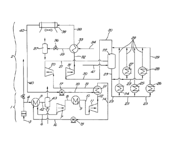
figure 1 schematically shows a flow diagram of two
industrial processes connected together according to
the invention;
figures 2 to 5 show the heat flow as a function of the
temperature through the heat exchangers 5, 9, 13 and 33
of figure 1;
figure 6 shows the pressure enthalpy diagram of
ammonia.
Figure 1 shows the flow diagram of a circuit for heat
recovery 1 of a first industrial production process that is
coupled to a second circuit for cold production 2 of a
second industrial production process. The first industrial
production process 3 supplies hot gases or vapours that
flow through pipe 4 to a heat exchanger 5 that forms part
of the first circuit for heat recovery 1 and in which the
first energy carrier, a mixture of water and ammonia, of
this first circuit is heated and guided via pipe 6 to a
compressor 7, suitable for compressing a two-phase mixture
from where the compressed energy carrier is guided via pipe
8 to a second heat exchanger 9 for steam production, and is
further guided via pipe 10 to an expander 11 in which the
first energy carrier is expanded and further guided via
pipe 12 to a third heat exchanger 13 for heat transfer to a
circuit for cold production in the second industrial
process 2, and is guided further via pipe 14 to a pump 15
that drives the first energy carrier of the first circuit
to the first heat exchanger 5 via pipe 16, in order to be
heated again and to go through the first circuit 1 again
for energy recovery.
CA 2915555 2017-10-16
13
The pump 17 in the second circuit for cold production 2
drives the second energy carrier of this second circuit for
cold production, i.e. ammonia, via pipe 18 to the heat
exchanger 13 in which the energy carrier absorbs heat from
the first circuit for energy recovery 1, and is guided via
pipe 19 to an expander in which the second energy carrier
is expanded, and is further guided via pipe 21 to a
separator 22 for separating the gas phase and the liquid
phase of the energy carrier from where the liquid phase of
the energy carrier is guided via pipe 23 to industrial
refrigerating devices, in this case a freezer tunnel 24, a
frozen storage area 25 and a chilled area 26 for the
collection of orders, and to other refrigerating
installations 27,28 that all form part of the second
industrial production process where cold is required.
The evaporated energy carrier from the refrigerating
devices is combined with the gas phase from the separator
22 via the pipes 29 and further guided via pipe 30 to a
compressor 31 from where the compressed gas is guided via
pipe 32 to the heat exchanger 33 where surplus heat can be
emitted to a flow of demineralised water 34, that can flow
to a steam generator 37 via pipe 35 when the tap 36 is
open. The second energy carrier of the second circuit for
cold production is guided from the heat exchanger 33 via
pipe 38 to a heat exchanger 39, in which the second energy
carrier is condensed by an air flow, after which the
second energy carrier is further guided via pipe 40 to the
pump 17 from where the energy carrier is further guided by
pipe 18 and reused in a subsequent cycle of the second
circuit 2 far cold production. Additional supplements of
CA 2915555 2017-10-16
14
second energy carrier in the second circuit for cold
production can be added via pipe 41 to the liquid phase in
the separator 22. Via pipe 42 hot gases, that are supplied
from the first production process 3, are used for heating
water .in the generator 43 for hot water.
Figures 2 to 5 graphically show the relationship between
the temperature in C of the energy carrier and the heat
flow in KJ/s through the subsequent heat exchangers: 5
(figure 2), 9 (figure 3), 13 (figure 4) and 33 (figure 5).
The temperature of the flow that is heated (OUT), and of
the flow that is cooled (IN) in the heat exchanger, is
indicated in each case.
Figure 6 shows a Mollier diagram of ammonia, the preferred
second energy carrier of the second circuit for cold
production, whereby the enthalpy is presented along the
abscissa in kJ/kg, and the pressure along the ordinate in
MPa.
The curve presents all pressure and enthalpy points where
the liquid phase (below the curve) is in equilibrium with
the gas phase (above the curve).
The operation of the device 1 is very simple and as
follows.
A first production process that requires heat can be an
industrial frying installation for French fried potatoes
for example, in which they are pre-fried, or it can be an
installation for frying potato crisps.
CA 2915555 2017-10-16
15
The first production process 3 that requires heat is
provided with a first circuit 1 for energy recovery in
which the energy present in the hot vapours originating
from the first production process 3 is partly recovered by
transferring the heat of the hot gases in a heat exchanger
5 to a first energy carrier, being a mixture of water
and ammonia, present in this first circuit 1 and then
expanding the first energy carrier in an expander 11 with
which electrical energy is generated that can be used in
the process again.
Another fraction of the energy present in the hot vapours
is utilised to generate hot water by guiding this fraction
through pipe 42 to a hot water generator 43.
Another fraction of the energy present in the hot gases is
transferred via heat exchanger 13 from the first energy
carrier in the first circuit 1 for energy recovery to the
second energy carrier, i.e. ammonia, in a second circuit 2
for cold production, whereby the transferred heat is
utilised to heat the second energy carrier of the second
circuit 2 for cold production before it is expanded in
expander 20 with which electrical energy is generated that
can be used in the process again.
The cooled second energy carrier of the second circuit 2 is
guided to a separator 22 that separates the liquid phase of
the energy carrier from the gas phase, after which the
liquid phase (-33 C) is utilised in the second industrial
process that requires cold, and from which the
CA 2915555 2017-10-16
16
refrigerating installations are supplied with the liquid
phase of the second energy carrier via the pipes 23 so that
applications, such as a freezer tunnel 24, a frozen storage
area 25, a collection zone 26 for frozen goods and other
refrigerating installations 27,28 can be cooled. The second
industrial process that requires cold can be the frozen and
chilled storage of foodstuffs for example.
For maximum energy recovery for the two coupled industrial
processes it is advantageous to have a different energy
carrier in the first circuit for energy recovery and in the
second circuit for cold production. In the given example
the first energy carrier of the first circuit is water with
a fraction of ammonia, while the second energy carrier in
the second circuit is ammonia.
After expansion in the first expander 11 the first energy
carrier is a two-phase flow that has already been cooled,
but from which more heat energy can be emitted to the
second energy carrier, pure ammonia, that has a much lower
boiling point (-33 C), and this absorbs heat in the heat
exchanger 13. This additional heat is utilised in the
second expander 20 of the second circuit for cold
production, where the energy carrier of the second circuit
is expanded.
The ammonia of the second circuit for cold production
heated in the heat exchanger 13 is expanded in the second
expander 20 whereby the second energy carrier becomes two
phase (liquid and gas), whereby these phases are separated
from one another in the separator 22. The liquid phase,
CA 2915555 2017-10-16
17
liquid ammonia, has a temperature of -33 C and can be used
for the connected industrial refrigerating installations.
The pressure-enthalpy diagram of figure 6 shows how much
energy (work) can be recovered by lowering the pressure of
ammonia in the liquid phase to a two-phase system, whereby
this energy is extracted from the expander as electricity.
In the following tables the energy coefficient of
performance or COP is calculated for two examples of a
heat-requiring process to a cold-requiring process.
Table 1 gives the energy account for an installation for
French fried potato production, coupled to a freezing
installation. The energy recovered column gives the sum of
all saved energy, while the energy supplied column gives
the sum of the energy that had to be supplied to enable
recovery. The ratio of the recovered energy to supplied
energy or COP is 3.95 in this case and is higher than the
COP for the total process in which the circuits for energy
recovery and cold production are not coupled.
CA 2915555 2017-10-16
CA 2915555 2015-12-16
PCT/IB 2014/001 244 - 21-08-201
18
Energy account potato crisp production and refrigerating
installation
' Energy saved Energy supplied
gain kWh Loss kWh
Hot water 323 Electricity 1206
Water/steam 815
Steam 1888
Refrigeration 1744
Water prod.
Table I: energy account for French fried potato production
coupled to freezing installation.
Table II shows the energy account for an installation for
potato crisp production, without coupling to a second
industrial process. The energy recovered column gives the
sum of all saved energy, while the energy supplied column
gives the sum of the energy that had to be supplied to
enable recovery. The ratio of the recovered energy to
supplied energy or COP is 4.59 in this case.
Energy account potato crisp production
Energy saved Energy supplied
gain kWh Loss kWh
Hot water 595 Electricity 896
Oil heating 3513
Water Prod.
Table II: energy account for potato crisp production.
AMENDED SHEET
Uk 293.5555 2015-12-16 PCT/IB 2014/001 244 - 21-08-
201
4 19
It goes without saying that the invention can be applied to
couple any industrial processes whereby one process
requires heating and the other process requires cooling.
The invention can also be applied at different temperature
ranges and with different energy carriers than those stated
in the examples, as long as they can be two-phase for the
first circuit for heat recovery.
The present invention is by no means limited to the
embodiments described as an example and shown in the
drawings, but a device for energy saving according to the
invention can be realised in all kinds of forms and
dimensions, without departing from the scope of the
invention, as described in the following claims.
AMENDED SHEET