Note: Descriptions are shown in the official language in which they were submitted.
CA 02915745 2015-12-1.6
WO 201 4/202942 PCT/GB2014/00706
- I -
Irprovemente in Waste_Heat Recovey...Units
The present invention relates to waste heat recovery units
(WHRUs),
$
Gas turbines are commonly used in oil and gas facilities,
both onshore and offshore, to provide shaft power to drive
compressors or other machinery and for power generation. The
gas turbine exhaust consists of a large quantity of hot gas,
typically- in the. range of 450-600, Such oil/gas facilities
typically also require heat for other parts of the process.
Therefore heat can be recovered from the gas, turbine exhaust
by means of a waste heat recovery unit, which is a heat
exchanger using heat from the exhaust gasses to heat a
stream of water, oil or other fluid.
A. WHRU essentially consists of a heat exchanger with an
array of tubing through which a stream of fluid to be heated
is. circulated. Exhaust gases from the gas' turbine are passed
around the exterior of the tubing thereby transferring heat
to the fluid stream within the tubing.
'
It is desirable to reduce the size and weight of WERUs,
especially for offshore applications. This can be achieved
by maximiaing the heat transfer co-efficients, thus
minimising the size and weight of the tube bank. It is also
desirable to recover the maximum possible amount of heat to
reduce the need to satisfy additional heat requirements by
burning fossil fuels.
The present invention provides a waste heat -recovery unit
comprising a duct for hot gas, wherein the duct is divided
,
CA 02915745 2015-12-16
WO 201 4/202942
PCT/GB2014/00706
into first, second and:third adjacent and parallel channels
each with an inlet and an outlet, a heat exchanger located
in each of the first and third channels, the second channel
being located between the first and third channels and
providing a bypass channel,. further comprising a damper
system operable to selectively open and close the inlets of
the first, second and third channels.
In this way, a more compact arrangement is provided which is
easier to manufacture and maintain and requires a smaller
space envelope.
Preferably, the damper system comprises a plurality of
rotatable blades mounted to walls dividing the duct into the
first, second and third channels, and connected to a common
actuator.
Preferably, this actuator is operable. to rotate the blades
simultaneously and in opposite directions, whereby the
blades are rotated towards one another to close the 'inlet to
the bypass channel and are rotated away from another to
.close the inlets to the heat exchanger. channels.
Preferably, the cross section. of each channel is
substantially rectangular
- In one embodiment, each heat exchanger comprises an. array of
tubing for circulating fluid to be heated, the tubing
supported by a support structure and extending across the
respective heat exchanger channel, wherein a portion of the
array extends through the support structure such that a
plurality of tubing portions are located outside the main
CA 02915745 2015-12-16
WO 201 4/202942
PCT/GB2014/00706
- 3 -
flow channel, the tubing portions arrangeu awjacent to and
spaced from one another, and further comprising a plurality
of baffles each located. between adjacent tubing portions to
at least partially fill the space in between them.
Preferably, the tubing comprises a portion of finned larger
outer diameter extending across the duct and through the
support structure, and a. portion of smaller out diameter-
located external to the support structure, such that a
smaller- spacing is provided between adjacent larger outer
diameter tubing portions, and a larger spacing is provided
between adjacent smaller outer diameter tubing portions, and.
wherein the baffles are provided in a larger spacing. .
Each baffle may comprise a rigid plate within an outer
insulating blanket. By way of example, the rigid, plate may
be formed of metal and the blanket of ceramic or body
soluble fibres,
Preferably, the damper system comprises a plurality- of
rotatable blades, each blade comprlsing an upstream plate
spaced from a downstream plate, and means to supply
pressurised as into the spacing between the upstream and
downstream plates, wherein a plurality of apertures are
formed in at least some of the downstream plates to allow
leakage of pressurised gas.
In a second aspect, the present invention, provides a heat
exchanger for a waste heat recovery unit, comprising a duct
defining a main flow channel for hot gas, an array of tubing
supported by a support structure and extending across the
duct for circulating fluid to be heated, wherein part of the
CA 02915745 2015-12-16
WO 201 4/202942 MC-
VG B 20 1 4 / 050706
- 4 -
array extends through the support structure such that a
plurality of tubing portions are located outSide the main
flow channel, adjacent to and spaced from one another, and
further comprising a plurality of baffles each located.
between adjacent tubing portions so as to at least partially
fill the spacing between them.
In a third aspect, the present invention provides a waste
heat recovery unit comprising at least one duct for
1.0 directing hot gas to a heat exchanger unit and at least one
as duct to bypass hot gas around the heat- exchanger
unit, and a damper system comprising a plurality of
rotatable blades, each blade rotprising an upstream plate
spared from a downstream plate, and means to supply
pressurised gas into the spacing between the upstream and
downstream plates, wherein a plurality of apertures are. =
formed in at least some of the downstream plates to allow
leakage of pressurised gas into the or each heat exchanger
duct.
The invention will now be described in detail by way of
example only and with reference to the accompanying drawings
in which;
Figure. 1 is a. schematic illustration of a conventional
waste heat recovery unit;
Figure 2 is a schematic illustration of a conventional
WHRUnwith an integral bypass duct;
Figure 3 is a schematic illustration of a conventional
WHRU with a separate bypass duct;
CA 02915745 2015-12-16
WO 201 4/202942 MC-
VG B 20 1 4 / 050706
- 5 -
Figure 4 is a schematic perspective view of a central
bypass configuration WHRU in accordance with the present
invention-;
Figure 5 is a cross section. of Figure 5 along the line
AA;
Figure 6 is an enlarged detail view of a baffle plate
system for use with the present. invention;
Figure 7 is a schematic illustration of a WHRU damper
blade for use with the present invention.
A typical- conventional WHRU configuration is shown.
schematically in Figure 1, The WHRU 10 comprises a duct 12
for carrying hot exhaust gases indicated by. arrows E) from
a gas turbine 14 to an array- of heat exchanger tubing 16.
For clarity, a single length of tubing 16 is shown. In
practice, a plurality of such tubes are provided and May be
referred to as a bundle or coil. As shown, the tubing 16
passes across the duct 12 multiple times with -18e turns at
each side, The tubing 16 is supported on each side, and
sometimes at intermediate points, by tube sheets 18, The
180 return bends 20 of the tubing 16 are located in header
boxes 22 on the exterior side of the tube sheets 18, out of
the main flow channel. The fluid to be heated is circulated
through the tubing 16i usually in a counter current
configuration, entering at the upper end of the WHIM 10 and
exiting at the lower end as shown by the arrows F in Figure
,
.1.
CA 02915745 2015-12-16
WO 201 4/202942
PCT/GB2014/00706
- 6 -
In oil and gas facilities utilising WHRUs, the required
amount of heat can vary with plant requirements and. feed
stock changes over the lifespan of the equipMent. In
addition, the flow and temperature of the hot gas from the
gas turbine may vary with ambient conditions and mach.ine
loading. Current practice is to design the WNRU for the
worst case combination of gas turbine exhaust conditions and
heat demand. However, this means that for most of the tAme
surplus heat is available. Current systems control this by
bypassing a. portion of the gas turbine exhaust flow around
the heat exchange tubing array.
One popular configuration uses an integral bypass
arrangement as shown schematically in Figure 2, This
arrangement consists of a bypass duct B. in parallel with the
duct 12 containing the heat exchanger tubing 16, creating
two parallel streams for the exhaust. gas, Each of the ducts
12, 13 is provided with a damper system D to selectively open
and close the ducts, The damper systems are typically
mechanically linked to each other so that as one opens the
other closes. This enables the flow of hot gas to the tubing
16 to be controlled.
However, there are a number of disadvantages with this
arrangementi it is necessary to have some space between the
two parallel channels and this increases the overall apace
requirement for the unit. Indeed, in some configurations, as
shown in Figure 3, the bypass duct B is entirely separate
and is set at a much greater distance from the duct 12
including the WHRU tubing 16, to avoid leakage of heat from
the bypass duct to the. tubing 16. However, this further
increases the space requirement for the whole unit, In
CA 02915745 2015-12-16
Mi() 20 1 4/202942 PCT/GB2014/00706
- 7 -
addition, the walls of the bypass duct B are typically made
_
of steel and the weight of the unit is thus increased, which
is disadvantageous in offshore- of applications. The
isolation damper for the WBRU Section of the duct 12 is
large and this adds to the overall cost of the unit, The
tubing 16 of the WHRO is a single item of significant weight
and this may. even exceed. crane capacity of the offshore
facility.
=
Another solution is known as the "CIBAS" design. This uses a
central bypass channel concentric with and surrounded by an
annular heat exchange duct containing an. annular array of
tubing. This has some advantages over the system mentioned
above in that there is no gap between the separate ducts for
the heat exchange tubing and for the bypass flow and a large
damper System is avoided.
However, this design also has major drawbacke. The tubes of
the heat exchanger have to be bent into the annular
configuration which adds to the cost of manuiacture. and '
creates integrity. risks. The annular arrangement means that
welds in the construction are not accessible and individual
tubes cannot be removed for maintenance. In addition, the
overall circular design does not take advantage of the
corners of an available plot of space on a facility.
The present invention provides an alternative configuration
in order to address these issues. As shown in Figure4 the
WKRU 10 again comprises a duct 12 for the flow of hot
exhaust gas from the gas turbine. At the inlet to the wHRU
section the duct 12 may be of circular cross section as
shown, or rectangular or any other convenient shape, but the
CA 02915745 2015-12-16
WO 201 4/202942 PCT/GB2014/00706
- 8 -
cross section of the 1,41.1aU itself is generally square or
rectangular. Two dividing walls 40, 42 separate the duct 12
into three adjacent parallel channels 44, 46, 4:4 of
generally rectangular or square cross. section.
The outer channels 44, 48 each contain an array of heat
exChange tubing although this is not shown in Figure 4 for
clarity, This may be arranged in any conventional manner. It
may include the 'baffle plate system described further below.
'MB central channel 46 does not include any heat exchange
tubing. and provides a bypass duct.
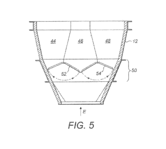
As shown in Figure 5, a damper system 50 controls the flow.
of exhaust gas and determines which ducts It will pass
through. The damper system 50 typically comprises a pair of
damper blades 52, 54 which are rotatably mounted at the
lower extremity of the dividing walls 40, 42,
.
Preferably, rotation of the damper blades 52, 54 is
Controlled by a. common actuator so that the blades 52, 54
will rotate in Unison but in opposite directions. Thus, to
pass hot gas through the two beat exchanger Arrays in the
outer channels 44, 48, one damper blade 52 is rotated
anticlockwise and the other damper blade 54 is rotated
clockwise so that they move towards each. other and together
they close the entrance to the bypass channel 46.
=
In order to close the heat exchanger channels 44, 48 the.
actuator rotates the damper blade 52 clockwise and the other
damper blade 54 anticlockwise in order to open the bypass.
channel 46 and close the heat exchanger channels 44, 48, The
CA 02915745 2015-12-16
WO 201 4/202942 PCT/GB2014/00706
- 9 -
damper blades 52, 54 may also be positioned at an
intermediate point so that some flow passes through the heat
exchanger channels 44, 48 and some through the bypass
channel 46.
Thus, a WHRU including a bypass duct is provided in a
compact arrangement which is more straightforward to
manufacture and maintain and has a reduced space requirement
than the previous configurations.
,:,n..,
In the construction of a. WERU, whether of a conventional
configuration or the central bypass configuration described
above, the tubing 16 and tube sheets 18 require space to
expand as they heat up in the flow of exhaust gas.
Therefore, clearances must be left in the structure and it
is not possible to completely seal all the gaps between the
tubing 16 and the tube sheets 18. Consequently, some exhaust
gases will escape through such gaps and bypass the main flow
. channel containing- the majority of the array of tubing 16.
To compensate for the losses caused by such bypass flow,
conventional systems may be made larger and 'heavier to
maintain a desired heat transfer performance. However:, this
conflicts with the general desire to reduce size and weight
of the HRU.
In a further feature of the present invention a baffle
system to' restrict such bypass flow of hot gas may be
provided, As shown in Figure 8, the portion 24 of the tubing
16 within the main flow channel of the duct 20 and between
the tube sheets 18 has an enlarged outer diameter and
increased surface area. Typically this is created by forming
CA 02915745 2015-12-16
WO 201 4/202942 PCT/GB2014/00706
- 10 - =
a helical fin which is -welded to the exterior of the tubing
16 to provide a larger surface area for heat transfer. In a
conventional system, the parts of the tubing 16 which are
within the header box 22 and are external to the tube sheets
18 and the main flow channel, include some of the portion 24
with the fin, and also a reduced outer diameter portion 26,
without the fin, for forming the return bends 20.
Accordingly, a small gap 28 is left: between adjacent parts
of the larger diameter portion 24 of the tubing 16, where
the fin is present A larger gap 30 is left between adjacent
parts of the smaller diameter portion 26 of the tubing 16,
where no fin is present.
Furthermore, there is a gap 29 between the tube sheet 18 and
the larger diameter portion 24 of the tubing: 16 which
includes the fin This gap 29 is necessary for contruction
and to allow. for thermal expansion, but it creates a leakage
path indicated by arrows L which can reduce the performance
of the heat exchanger as hot gasses bypass the main flow
channel and the main body of the tubing. 16. In addition, the
tube sheet. 18 is normally not integral with the wall of the
duct 12 and there are further gaps 11 around the edges of
the tube sheet 16, creating a further leakage path also
indicated by arrows L.
2s
In the present invention baffle plates 32 are located in the
larger gaps 30 between the smaller diameter portions 26 of
the tubing 6 in the header box 22. Each baffle plate 52
consists of a rigid inner plate 34, for example a metal
plate approximately 3mm in thickness, which is encased in an
insulating outer blanket 36, for example a Ceramic fibre
blanket approximately 25mm thick. The baffle plates 32 block
CA 02915745 2015-12-16
WO 201 4/202942
PCT/GB2014/00706
- 11 -
the larger gaps 30 so that the bypass flow of exhaust. gas
which has entered the header box 22 via gaps 29 and 31, can
then only flow past the exterior of the larger diameter
finned portion 24 of the tubing 16. Thus, although some
. .!.i bypass flow still occurs, this can be utilised for heat
transfer into the fluid within the tubing 16 because it
contacts the fin providing the larger surface area.
In this way the heat transfer performance of. the WW1 10 can.
be maintained despite the bypass flow and without increasing
the size and weight of the unit. The baffle plates may be
incorporated in a WHRU of conventional design, or the
central bypass configuration described above,
A. further issue which arises with. IIHRUt which include a
bypass channel is that in order to run the gas turbine, a
small flow of heat transfer medium must be maintained
through the array of tubing 16 even if substantially all of
the exhaust flow is passed through the bypass duct. This is
because there may be some leakage of heat back to the heat
exchange tubing from the outlet of the bypass flow channel,
or heat leakage through. the damper system. This heat leakage
is indicated by arrows L in Figure 2.
One existing solution is to have an entirely separate bypass
duct widely spaced from the duct 12 containing the heat
exchange tubing as in Figure 5. However, this solution
requires more space for the entire unit, adds weight and
creates the need for an additional stack emission point.
Another known solution is to form the damper blades from two
parallel plates with a spacing between them. Pressurised air
CA 02915745 2015-12-16
WO 2014/202942
PCT/GB2014/050706
- 12 -
is supplied into the spacing, which can exit at edges of the
blade. Thus, an area of increas d pressure is provided at
the damper, which. is a higher pressure that. the flow of
exhaust gas and serves to further seal the entrance to the
WHRU.
However, this is not effective in preventing, heat leakage
occurring at the downstream end from the bypass duct outlet
back to the heat exchanger outlet.
In Figure 7, a damper blade 60 for addressing this problem
is illustrated. The damper blade 60 cc prices a pair of
spaced parallel plates 62, 64. In use, these are arranged
with the plate 62 upstream and the plate 64 downstream.
Thus, when the damper is closed, exhaust gasses will impinge
on the upstream plate 62. A series of apertures 66 is
provided in the downstream plate 64. This deliberately
allows the pressurised seal air supplied to the interior
spacing between the plates 62, 64 to leak out of the
downstream plate 64 and into the flow channel of the WHRU,
In this way, the sealing effect is enhanced and the
temperature of the heat exchange tubing 16 is kept below.
acceptable limits, even when there is no flow of heat
transfer fluid in the tubing 16. This has the advantage of
enabling the operator to start or continue to run the gas
turbine even if the system which circulates the heat
transfer fluid through the tubing 16 is out of service.
This arrangement of perforated damper plates may be
incorporated in any conventional WHRU design, or used in
CA 02915745 2015-12-16
WO 2014/202942 .
PCT/GB2014/050706
- la. -
't'ond',.1n.ctii.Jt. *ith lotther or .oth: tIle.1-WfIe= plate syetett and
the: ...central. bypa$0 .penf.igur*.,õWo.p.e:Oeeex.ed. abOve.
ThUs, the. preent Inventiell. provides an improved. Vagte 'beet
recovery it whict 10 :mere. ftf.i.ce-1...lt thi,.m: twilvehtittal.
sy4ltetz, The: ..z"zikilled peron will.appteciete: that v.i.011$
,todificatibb tAy be made. to: the px.-...eci,ze det4i1A..debtribed
above :whilst not departing from the: scope: of the. iftVe:atioh.
A.O. pVt. out: In the .tolaow.,i,hg e'J.,a,i.xlie