Language selection

Search

Patent 2915896 Summary

Third-party information liability

Some of the information on this Web page has been provided by external sources. The Government of Canada is not responsible for the accuracy, reliability or currency of the information supplied by external sources. Users wishing to rely upon this information should consult directly with the source of the information. Content provided by external sources is not subject to official languages, privacy and accessibility requirements.

Claims and Abstract availability

Any discrepancies in the text and image of the Claims and Abstract are due to differing posting times. Text of the Claims and Abstract are posted:

  • At the time the application is open to public inspection;
  • At the time of issue of the patent (grant).
(12) Patent: (11) CA 2915896
(54) English Title: CONE BRAKE FRICTION SURFACE COATING
(54) French Title: REVETEMENT DE SURFACE DE FRICTION DE FREIN A CONE
Status: Granted
Bibliographic Data
(51) International Patent Classification (IPC):
  • F16D 49/00 (2006.01)
  • C23C 4/129 (2016.01)
  • B64C 11/00 (2006.01)
  • C23C 4/10 (2016.01)
  • F16H 57/02 (2012.01)
(72) Inventors :
  • HASSLER, KYLE A. (United States of America)
  • WARRENBURG, SEAN (United States of America)
  • SWIFT, JOSEPH A. (United States of America)
  • MOCK, KEVIN (United States of America)
  • WINELY, MARK (United States of America)
(73) Owners :
  • ROLLS-ROYCE CORPORATION (United States of America)
(71) Applicants :
  • ROLLS-ROYCE CORPORATION (United States of America)
(74) Agent: GOWLING WLG (CANADA) LLP
(74) Associate agent:
(45) Issued: 2021-08-03
(22) Filed Date: 2015-12-21
(41) Open to Public Inspection: 2016-07-13
Examination requested: 2020-12-04
Availability of licence: N/A
(25) Language of filing: English

Patent Cooperation Treaty (PCT): No

(30) Application Priority Data:
Application No. Country/Territory Date
62/102,686 United States of America 2015-01-13

Abstracts

English Abstract

An exemplary cone brake device includes a brake drum and a thermal sprayed coating deposited and bonded to the outer surface. The thermal sprayed coating is configured to engage a friction lining when one of the brake drum and the friction element is moved toward the other of the brake drum and the friction element, so as to decrease the speed of an aerospace propeller.


French Abstract

Un dispositif de frein conique en exemple comprend un tambour de frein et un revêtement métallisé au pistolet et lié à la surface extérieure. Le revêtement par métallisation au pistolet est configuré pour entrer en contact avec une garniture de friction lorsque le tambour de frein ou lélément de frottement est déplacé vers lautre, de sorte à réduire la vitesse dune hélice aérospatiale.

Claims

Note: Claims are shown in the official language in which they were submitted.

CLAIMS
What is claimed is:
1. A cone brake device, comprising:
an outer member having an annular inner surface;
a friction element attached to the annular inner surface of the outer member;
a brake drum having an outer surface and configured to move toward the
friction element;
and
a thermal sprayed high velocity oxygen fuel coating including molten or semi-
molten
material attached to the outer surface of the brake drum and having a
thickness greater than 1.5
mm, and the thermal sprayed coating is configured to engage the friction
element when one of the
brake drum and the friction element is moved toward the other of the brake
drum and the friction
element.
2. The cone brake device of claim 1, wherein the thermal sprayed coating is
a tungsten
carbide ¨ 17% cobalt hard material.
3. The cone brake device of claim 1, wherein the friction element is a
sintered bronze material.
4. The cone brake device of claim 1, wherein the outer surface is a
frustoconical surface.
5. The cone brake device of claim 1, wherein the brake drum is a ring
having a first end and
a second end, and the ring has an outside diameter that tapers from the first
end to the second end.
6. The cone brake device of claim 1, wherein one of the outer member and
the brake drum is
connected to an aerospace propeller.
7. A gear box, comprising:
a gear set; and
Date Recue/Date Received 2020-12-04

a cone brake device including an outer member, a friction element, a brake
drum and a
thermal sprayed high velocity oxygen fuel coating including molten or semi-
molten material and
having a thickness greater than 1.5 mm;
wherein the outer member has an annular inner surface;
wherein the friction element is attached to the annular inner surface of the
outer member;
wherein the brake drum has an outer surface and is configured to move toward
the friction
element; and
wherein the thermal sprayed high velocity oxygen fuel coating is attached to
the outer
surface of the brake drum, and the thermal sprayed coating is configured to
engage the friction
element when one of the brake drum and the friction element is moved toward
the other of the
brake drum and the friction element.
8. The gear box of claim 7, wherein the thermal sprayed coating is a
tungsten carbide ¨ 17%
cobalt hard material.
9. The gear box of claim 7, wherein the friction element is a sintered
bronze material.
10. The gear box of claim 7, wherein the outer surface is a frustoconical
surface.
11. The gear box of claim 7, wherein the brake drum is a ring having a
first end and a second
end, and the ring has an outside diameter that tapers from the first end to
the second end.
12. The gear box of claim 7, wherein one of the outer member and the brake
drum is connected
to an aerospace propeller.
13. An aircraft propeller system, comprising:
an aerospace propeller; and
a gear box including a gear set and a cone brake device;
wherein the gear set is configured to rotate the aerospace propeller;
6
Date Recue/Date Received 2020-12-04

wherein the cone brake device includes an outer member, a friction element, a
brake drum
and a thermal sprayed high velocity oxygen fuel coating including molten or
semi-molten material
and having a thickness greater than 1.5 mm;
wherein the outer member has an annular inner surface;
wherein the friction element is attached to the annular inner surface of the
outer member;
wherein the brake drum has an outer surface and is configured to move toward
the friction
element; and
wherein the themial sprayed high velocity oxygen fuel coating is attached to
the outer
surface of the brake drum, and the thermal sprayed coating is configured to
engage the friction
element when one of the brake drum and the friction element is moved toward
the other of the
brake drum and the friction element, so as to decrease a speed of the
aerospace propeller.
14. The aircraft propeller system of claim 13, wherein the thermal sprayed
coating is a tungsten
carbide ¨ 17% cobalt hard material.
15. The aircraft propeller system of claim 13, wherein the friction element
is a sintered bronze
material .
16. The aircraft propeller system of claim 13, wherein the outer surface is
a frustoconical
surfac e.
17. The aircraft propeller system of claim 13, wherein the brake drum is a
ring having a first
end and a second end, and the ring has an outside diameter that tapers from
the first end to the
second end.
7
Date Recue/Date Received 2020-12-04

Description

Note: Descriptions are shown in the official language in which they were submitted.


CONE BRAKE FRICTION SURFACE COATING
[0001]
FIELD OF TECHNOLOGY
[0002] The present disclosure relates to gearboxes for aircraft propeller
systems and more
particularly, but not exclusively, to a gear box having a cone brake device
that has a thermal sprayed
coating, which has greater hardness so as to increase the service life of the
brake device.
BACKGROUND
[0003] Turboprop manufacturers produce cone brake devices that are
configured to slow down
the rotation of a propeller during and after engine shutdown. In particular,
the typical cone brake
device can have an outer surface that is urged into direct contact with an
element connected to the
propeller. Over the service life of the turboprop, the outer surface can
become worn, thus adversely
affecting the coefficient of friction at the interface between the outer
surface and the component.
For this reason, the propeller may freely "windmill" during and after engine
shutdown.
100041 It would therefore be helpful to provide a cone brake device that is
configured to slow
down rotation of a propeller over a longer service life of the turboprop, thus
reducing maintenance
of the turboprop and improving overall performance of the same.
1
Date Recue/Date Received 2021-02-12

CA 02915896 2015-12-21
BRIEF DESCRIPTION OF THE DRAWINGS
[0005] While the claims are not limited to a specific illustration, an
appreciation of the various
aspects is best gained through a discussion of various examples thereof.
Referring now to the
drawings, exemplary illustrations are shown in detail. Although the drawings
represent the
illustrations, the drawings are not necessarily to scale and certain features
may be exaggerated to
better illustrate and explain an innovative aspect of an example. Further, the
exemplary illustrations
described herein are not intended to be exhaustive or otherwise limiting or
restricted to the precise
form and configuration shown in the drawings and disclosed in the following
detailed description.
Exemplary illustrations are described in detail by referring to the drawings
as follows:
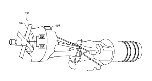
[0006] FIG. 1 schematically illustrates some aspects of one non-limiting
example of an aircraft
propeller system including a gear box that has a cone brake device, in
accordance with one non-
limiting exemplary embodiment of the present disclosure;
[0007] FIG. 2 is a cross-sectional view of one portion of the cone brake
device of FIG. 1, having
a conical drum and a thermal sprayed coating; and
[0008] FIG. 3 is an enlarged view of the conical drum of FIG. 2.
DETAILED DESCRIPTION
[0009] An exemplary cone brake device ("brake device") is described herein
and shown in the
attached drawings. The exemplary brake device is a component of a gear box
that is configured to
operate a propeller for an aerospace propeller system. The exemplary aerospace
propeller system
can be a single shaft, modular design military turboprop with a 14 stage axial
flow compressor
driven by a four stage turbine. However, the cone brake device can instead be
a component of other
suitable gear boxes for various propulsion or drive mechanisms corresponding
with any vehicle. In
this example, the cone brake device includes a brake drum and a thermal
sprayed coating deposited
and bonded to the outer surface of the brake drum. The thermal sprayed coating
is configured to
engage a friction lining when one of the brake drum and the friction lining is
moved toward the
other of the brake drum and the friction element, so as to decrease the speed
of an aerospace
2

CA 02915896 2015-12-21
propeller. One exemplary benefit of the thermal sprayed coating is that it
maintains its surface
roughness and increases the service life of the brake device, thus increasing
its overall performance.
[0010] Referring to Figure 1, there is illustrated one non-limiting example
of an aircraft
propeller system 100 having an aerospace propeller 102 and a gear box 104,
which includes a gear
set 106 that is connected to the propeller 102 and configured to rotate the
same. The gear box 104
further includes a cone brake device 108, which in this example, is configured
to decrease the speed
of the propeller 102.
[0011] Figure 2 illustrates a cross sectional view of a portion of the cone
brake device 108
("brake device"), having a brake drum 110, and Figure 3 is a cross-sectional
view of a portion of
the brake drum 110, illustrating that the brake device 108 has a thermal spray
coating 112. The
thermal spray coating 112 can have a thickness in the range between 20
micrometers to several
millimeters. Thus, the coating 112 is schematically represented by a line in
Figure 3, which is not
drawn to scale. Of course, the coating can instead have any thickness above or
below this range.
[0012] More specifically, as shown in Figure 2, the exemplary brake device
108 includes an
outer member 114, which has an annular inner surface 116. The brake device 108
also includes a
friction element 118, pad or lining, which is attached to the annular inner
surface 116. The friction
element 118 can be riveted to the outer member 114. However, the friction
element 118 can be
attached to the outer member 114 by other suitable fasteners and attachment
methods.
Furthermore, the brake drum 110 also has an outer surface 120, and in
particular, the brake drum
110 can be a ring 122 having a first end 124 and a second end 126, and the
ring can have an outside
diameter that tapers from the first end 124 to the second end 126, such that
the outer surface 120 of
the brake drum 110 is a frustoconical surface 128. The thermal sprayed coating
112 is attached to
the outer surface 120 of the brake drum 110, and the thermal sprayed coating
112 is configured to
engage the friction element 118 when the friction element 118 is moved toward
the brake drum 110
so as to contact the same, thus decreasing a speed of the propeller 102. Of
course, another example
of the brake device can be configured to move the brake drum toward the
friction element so as to
decrease propeller speed. One example of the coating 112 is a High Velocity
Oxygen Fuel (HVOF)
coating made of Tungsten Carbide ¨ 17% Cobalt hard material. The HVOF coating
is applied by a
3

CA 02915896 2015-12-21
thermal spray coating process in which molten or semi-molten materials are
sprayed onto the outer
surface 120 by means of the high temperature, high velocity gas stream. In
particular, this process
produces a dense spray coating that can be ground to a very high surface
finish. The HVOF coating
112 has an increased density and hardness, thus increasing resistance to
erosion, wear, and
corrosion, and maintaining the roughness of the coating 112 over a longer
service life of the brake
device 108. In other examples, other processes can be utilized for applying
the coating to the outer
surface.
[0013] The friction element 118 can be made of sintered bronze material.
Sintering is the
process of compacting and forming a solid mass of material by heat and/or
pressure without
melting it to the point of liquefaction. Sintering happens when the atoms in
the materials diffuse
across the boundaries of the particles, fusing the particles together and
creating one solid piece. One
exemplary advantage of the sintering process is that it can utilize heat below
the melting point of
the material, thus reducing manufacturing costs corresponding with materials
having considerably
high melting points, such as tungsten. The sintered material has multiple
distinctive structural
characteristics. As one example, the sintered material can preserve its purity
at least because of the
fewer steps in the fabrication process. Furthermore, in the sintering process,
there is an absence of
binding contact between segregated powder particles or "inclusions," as can
often occur in melting
processes.
[0014] All terms used in the claims are intended to be given their broadest
reasonable
constructions and their ordinary meanings as understood by those knowledgeable
in the
technologies described herein unless an explicit indication to the contrary is
made herein. In
particular, use of the singular articles such as "a," "the," "said," etc.
should be read to recite one or
more of the indicated elements unless a claim recites an explicit limitation
to the contrary.
4

Representative Drawing
A single figure which represents the drawing illustrating the invention.
Administrative Status

For a clearer understanding of the status of the application/patent presented on this page, the site Disclaimer , as well as the definitions for Patent , Administrative Status , Maintenance Fee  and Payment History  should be consulted.

Administrative Status

Title Date
Forecasted Issue Date 2021-08-03
(22) Filed 2015-12-21
(41) Open to Public Inspection 2016-07-13
Examination Requested 2020-12-04
(45) Issued 2021-08-03

Abandonment History

There is no abandonment history.

Maintenance Fee

Last Payment of $210.51 was received on 2023-12-08


 Upcoming maintenance fee amounts

Description Date Amount
Next Payment if standard fee 2024-12-23 $277.00
Next Payment if small entity fee 2024-12-23 $100.00

Note : If the full payment has not been received on or before the date indicated, a further fee may be required which may be one of the following

  • the reinstatement fee;
  • the late payment fee; or
  • additional fee to reverse deemed expiry.

Patent fees are adjusted on the 1st of January every year. The amounts above are the current amounts if received by December 31 of the current year.
Please refer to the CIPO Patent Fees web page to see all current fee amounts.

Payment History

Fee Type Anniversary Year Due Date Amount Paid Paid Date
Registration of a document - section 124 $100.00 2015-12-21
Application Fee $400.00 2015-12-21
Maintenance Fee - Application - New Act 2 2017-12-21 $100.00 2017-12-04
Maintenance Fee - Application - New Act 3 2018-12-21 $100.00 2018-12-04
Maintenance Fee - Application - New Act 4 2019-12-23 $100.00 2019-12-13
Request for Examination 2020-12-21 $800.00 2020-12-04
Maintenance Fee - Application - New Act 5 2020-12-21 $200.00 2020-12-08
Final Fee 2021-08-26 $306.00 2021-06-15
Maintenance Fee - Patent - New Act 6 2021-12-21 $204.00 2021-12-07
Maintenance Fee - Patent - New Act 7 2022-12-21 $203.59 2022-12-07
Maintenance Fee - Patent - New Act 8 2023-12-21 $210.51 2023-12-08
Owners on Record

Note: Records showing the ownership history in alphabetical order.

Current Owners on Record
ROLLS-ROYCE CORPORATION
Past Owners on Record
None
Past Owners that do not appear in the "Owners on Record" listing will appear in other documentation within the application.
Documents

To view selected files, please enter reCAPTCHA code :


To view images, click a link in the Document Description column. To download the documents, select one or more checkboxes in the first column and then click the "Download Selected in PDF format (Zip Archive)" or the "Download Selected as Single PDF" button.

List of published and non-published patent-specific documents on the CPD .

If you have any difficulty accessing content, you can call the Client Service Centre at 1-866-997-1936 or send them an e-mail at CIPO Client Service Centre.


Document
Description 
Date
(yyyy-mm-dd) 
Number of pages   Size of Image (KB) 
Request for Examination / PPH Request / Amendment 2020-12-04 12 385
Claims 2020-12-04 3 99
Interview Record Registered (Action) 2021-02-04 1 14
Amendment 2021-02-12 6 126
Description 2021-02-12 4 193
Amendment 2021-03-08 6 171
PPH OEE 2021-03-08 14 851
Final Fee 2021-06-15 4 125
Representative Drawing 2021-07-09 1 8
Cover Page 2021-07-09 1 36
Electronic Grant Certificate 2021-08-03 1 2,527
Abstract 2015-12-21 1 10
Description 2015-12-21 4 194
Claims 2015-12-21 4 100
Drawings 2015-12-21 2 24
Representative Drawing 2016-06-15 1 9
Cover Page 2016-08-03 1 35
New Application 2015-12-21 12 382