Note: Descriptions are shown in the official language in which they were submitted.
CA 02916599 2016-01-04
1
DESCRIPTION
Device for Combating the Varroa Mite in a Bee Brood
The invention relates to a device for combating the varroa mite in a bee
brood, comprising at least one middle wall that can be inserted in particular
into a beehive and that is provided with brood cells for female bees.
Bee colonies are generally kept by beekeepers in beehives, also called brood
boxes, and are used here to produce honey. The beehives are normally cu-
boid. Rectangular middle walls, suspended next to one another, are inserted
into the beehives and are surrounded by frames by means of which they can
be inserted removeably into the beehives. Within the context of the present
description and claims the term " middle wall" is to be understood here as
meaning a wall with any outline that is provided on one or on both sides with
pre-shaped brood cells independently of whether the middle wall is sur-
rounded by a frame or not.
In most cases the middle walls are in the form of rolled or cast sheets made
of bees wax, in which the brood cells are impressed in the form of hexagons
with equal sides and which respectively form the honeycombs. After sus-
pending the middle walls in the bee colony, the bees grip onto the honey-
comb pattern and extend the pre-formed brood cells with the aid of the bees
wax produced by them so as to form a brood comb.
As regards the middle walls, a distinction is made between middle walls with
brood cells for female bees ¨ the so-called worker inner cells, and brood
cells
CA 02916599 2016-01-04
2
for male bees ¨ the so-called drone cells. The latter have a considerably
greater diameter and depth than the worker inner cells.
For a number of years beekeepers have been confronted with a drastic in-
s crease in the mortality rate of bee colonies, in particular winter bee
colonies.
Mites that are harmful to bees, especially the varroa mite, are held responsi-
ble for the high mortality rate. In order to combat the varroa mite, basically
two methods have been used, namely on the one hand chemical treatment,
for example by means of organic acids, and on the other hand thermal treat-
ment. The disadvantage of the chemical treatment is that there is the risk
that
residues from the treatment product will pass into the honey. This risk does
not exist with the purely thermal treatment.
For the thermal treatment special heating cabinets have been developed in
is which the brood combs are subjected to a flow of warm air for a number
of
hours. For this purpose the brood combs infested with varroa mites are re-
moved from the beehive, and the bees sitting on the latter are shaken or
wiped off. The bee-free brood combs are then suspended in the heating cab-
inet. Then the temperature of the flow of warm air air is slowly increased
until
zo a temperature of between 39 und 42 C is reached in the brood cells. This
temperature is then maintained for a number of hours (WO 92/14355 Al and
EP 2 250 880 B1).
The treatment by means of a separate heating cabinet is very time-
25 consuming due the necessity of bringing the brood combs into the heating
cabinet and back into the beehive. Moreover, the purchase of the heating
cabinet represents a considerable, hardly cost-effective investment for ama-
teur beekeepers. Therefore, due to the simpler handling and the lower costs,
many beekeepers therefore still resort to the chemical approach.
CA 02916599 2016-01-04
3
As an alternative to the warm air treatment in separate heating cabinets it
has been proposed to combat the varroa mite by providing a middle wall or a
number of middle walls with brood cells for the drones with a heating device
that has a resistance heating element embedded in the middle wall and a
control device connected to the latter (see US 8,272,921 B1). The middle
wall equipped in this way or the middle walls equipped in this way are insert-
ed into the brood box and is/are extended by the bees to form a drone brood
comb or drone bee combs. During the development of the drone larvae into
adult drones the heating device can be switched on in order to heat the drone
brood comb or the drone brood combs. In a few minutes this causes the
drone brood comb(s) to heat up to approximately 65 C. After a similarly small
number of minutes the heating device is switched off again. This strong heat-
ing causes both the varroa mites and the drone brood to die.
It is an advantage of this system that no special heating cabinet with
handling
necessary for its use is required. It is a disadvantage, however, that the ef-
fectiveness is unsatisfactory because the combating of the varroa mites is
restricted to the drone brood comb designed for drones, and accordingly the
brood cells for the workers, which are substantially more important for the
bee colony population, remain untreated, and so unprotected. In addition,
that brood combs for the drone brood are only liable to a varroa mite infesta-
tion during the relatively short breeding season for drones, and so it is only
possible to combat the varroa mite during this time.
The object underlying the invention is to provide a device for combating the
varroa mite in a bee brood that is easy to handle and enables substantially
better protection of the bee colony from mites that are harmful to bees over
the entire yield period.
81793509
4
According to the invention this object is achieved with an apparatus of the
type specified at the start
in that an electrical heating device is provided that has a resistance heating
element embedded in
the middle wall with brood cells for female bees, and a control device
connected to the latter, the
control device being designed such that an automatically running heating
process can be initiated
with a temporally pre-determined heat-up phase that lasts until a temperature
of 39 C to 45 C,
preferably 39 C to 42 C, is reached in the bottoms of the brood cells in the
region of the resistance
heating element, and then with a subsequent phase of maintaining this
temperature for a
predetermined period of time. Therefore, the basic idea behind the invention
is to provide a device
with at least one middle wall with brood cells for female bees which, after
having been inserted into
the beehive, can be electrically heated in such a way that only the varroa
mites are killed here,
whereas the bees and bee larvae in this area remain unharmed. Therefore,
unlike with the device
according to US 8,272,921 B2, the heating also only takes place to a
temperature which is
exclusively harmful to the varroa mites. It has been shown that in this way it
is possible to combat
the varroa mite in an extremely effective way because the heating process
takes place where the
varroa mite is particularly harmful. In order to initiate the heating process
it is not necessary to
remove the brood comb from the beehive, i.e. the heating process is preferably
initiated in the
beehive itself, and so it is not necessary to handle the brood comb or the
brood combs.
In some embodiments, there is provided a device for combating the varroa mite
in a bee brood,
comprising at least one middle wall that can be inserted in particular into a
beehive and that is
provided with brood cells for female bees, an electrical heating device that
has a resistance heating
element embedded in the middle wall and a control device connected to the
latter which is designed
such that an automatically running heating process can be initiated with a
temporally predetermined
heat-up phase that lasts until a temperature of 39 C to 45 C, is reached at
the bottom of the brood
cells in the region of the resistance heating element and then with a
subsequent phase of
maintaining this temperature for a predetermined period of time, wherein the
resistance heating
element is in the form of a PTC resistor and the control device is configured
such that the
temperature in the heat-up phase and in the maintenance phase is controlled by
adapting the
respectively measured values for current and voltage in the PTC resistor to
values stored in the
control device.
When applying the basic idea behind the invention it is not ruled out to
additionally provide at
least one, preferably all of the middle walls with brood cells for drones,
with the heating device
according to the invention and to also subject these middle walls to the
heating process according
to the invention after insertion into the beehive and during the breeding
period in order to combat
the varroa mite in this area too. However, in order to protect the workers
this additional measure
is not necessary, especially as the varroa
CA 2916599 2018-04-03
CA 02916599 2016-01-04
mite infestation in the area of the brood cells hardly causes any damage to
the drones.
The resistance heating element can be of any shape and extension. Advan-
5 tageously it should not extend over the entire surface of the middle
wall, but
rather be restricted to a central area. It should cover at least 80% of the
brood surface. The upper feeding zone, the side cells for pollen stocks and
any empty remaining cells on the lower side can be kept free from the re-
sistance heating element.
Under no circumstances should the heat-up take place as quickly as with the
apparatus according to US 8,272,921 B1. So that the brood cells heat up
evenly and the bee brood is protected from rapid increases in temperature
the heat-up phase should last for at least 30 minutes, in particular at least
1
is hour. The heating up should take place evenly at a specific rate, for
example
a maximum of 0.1 C/min. The maintenance phase should also be consider-
ably longer than with the apparatus according to US 8,272,921 B2, i.e. at
least 30 minutes, in particular at least 1 hour, preferably at least 1.5
hours, in
particular 2 hours. It can also be considerably longer. Ultimately, the length
of
the maintenance phase is determined with the aim of on the one hand killing
the varroa mites that are in the brood cells of the brood combs, but on the
other hand of not consuming power needlessly.
The control device can be designed such that the lengths of time for the
maintaining and heat-up phase are set in the control device. However, the
control device can also be designed so that the user of the device according
to the invention can adjust the lengths of time and so adapt to the respective
situation in which the beehive is set up.
CA 02916599 2016-01-04
6
According to another feature of the invention provision is made such that the
control device is designed such that after the initiation of a first heating
pro-
cess at least one additional heating process is automatically brought about.
The intervals between two consecutive heating processes can be adapted to
the intensity of the varroa mite infestation. During the breeding period from
March to September heating processes can be initiated at weekly intervals,
for example every three weeks, the control device carrying this out automati-
cally. Other, for example longer intervals, can also be provided. It is
possible
here to set the intervals in the control device so that they are fixed.
Advanta-
geously however, the control device has a setting means for the beekeeper
so that the beekeeper can determine the length of time of the intervals him-
self, preferably within reasonable limits as gained from experience. It is im-
portant that the beekeeper does not have to observe and actuate the device
because the individual heating processes are initiated by the control device
itself without the beekeeper's involvement or intervention.
A particularly advantageous feature of the invention is that the resistance
heating element is in the form of a FTC resistor or thermistor. It is a charac-
teristic of these FTC resistors that the electric resistance increases approxi-
mately linearly with the temperature. This opens up the possibility of control-
ling the temperature in the heat-up phase and in the maintenance phase by
adapting the respectively measured values for current and voltage in the FTC
resistor to values stored in the control device. This type of control device
is of
elegant design and renders the installation of a temperature sensor in the
connected middle wall unnecessary.
In a particularly preferred configuration the device has a number of middle
walls with resistance heating elements embedded in the latter and which are
all connected to the control device by means of which a heating process can
then respectively be initiated in each of the middle walls. Preferably, as al-
CA 02916599 2016-01-04
7
ready mentioned above, these are all middle walls with brood cells for female
bees. Here the middle walls can form groups each comprising a number of
middle walls, each group being intended for use in a respective beehive.
Therefore, the device according to the invention is also suitable for combat-
ing the varroa mite in a number of beehives of a beehouse, the heating pro-
cesses being controlled centrally by a single control device in the middle
walls extended to form brood combs. As also already mentioned above, the
brood combs provided for the drone brood can also be included here by
these respectively also being subjected to a heating process according to the
invention.
In the configuration of the device according to the invention described above,
the control device should be designed such that the heating processes for
the individual brood combs are carried out one after the other. In this way
excessive heat input within a beehive and also excessive current consump-
tion which would occur if the heating processes ran in parallel is avoided.
The
individual heating processes should follow on immediately from one another.
However, this is not essential, i.e. for the purpose of further reducing the
heat
input of the beehive intervals of time can also be provided between two heat-
ing processes of adjacent middle walls or brood combs. After the conclusion
of the heating processes for all of the brood combs, in this respect
repetition
of these heating processes can also be provided, either in predetermined
intervals of time or predeterminable intervals of time that can be set. As al-
ready mentioned above, these intervals can be a number of weeks within a
breeding period.
The design of the control device can be extended in a wide variety of ways in
order to facilitate the beekeeper's control by means of the heating processes
initiated by the control device. The date and the time of each heating process
for each middle wall or brood comb can thus be stored and then be made
CA 02916599 2016-01-04
8
retrievable for the beekeeper. The same applies to any malfunctions that can
be indicated to the beekeeper by optical or acoustic warning elements. Such
malfunctions may occur in the energy supply or if there is insufficient power
supply to the resistance heating elements. This can all be recorded and be
indicated in a display. Ultimately, the overall aim is to design the control
de-
vice such that on the one hand the beekeeper is largely relieved of having to
take any action, but on the other hand he can monitor and query the function
of the device according to the invention at any time and, in addition, be in-
formed of any malfunctions.
In the drawings the invention is illustrated in more detail by means of an ex-
emplary embodiment. These show as follows:
Figure 1 two beehives with the device according to the invention for
combating varroa mites in a perspective illustration;
Figure 2 a vertical section through a middle wall for the beehives accord-
ing to Figure land
Figure 3 a side view of the middle wall according to Figure 2.
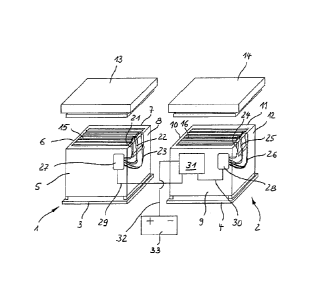
In Figure 1 two substantially cubical beehives 1, 2 are shown next to one an-
other. They each have a bottom wall 3 or 4 and four side walls 5, 6, 7, 8 or
9,
10, 11, 12 arranged at right angles to one another. Each of the beehives 1,2
has a removeable top wall 13 or 14 which are shown here in the vertically
lifted off state.
Suspended in each of the beehives 1, 2 is a plurality of middle walls ¨ identi-
fied, for example, by 15 and 16 -, that extend vertically and parallel to the
CA 02916599 2016-01-04
9
= side walls 5, 7 and 9, 11. Some of the middle walls 15, 16 are formed as
shown in Figures 2 and 3.
The middle wall 15 shown in Figures 2 and 3 is made of wax and is provided
on both sides with hexagonal brood cells, also formed from wax ¨ identified,
for example, by 17¨ that are largely configured as brood cells 17 for female
bees and only parts of which are drawn in Figure 2. The middle wall 15¨ like
all of the other middle walls 15, 16 ¨ is surrounded by a frame 18 by means
of which the middle wall 15 can be suspended in one of the brood boxes 1,2
so that it hangs down perpendicularly.
A resistance heating element in the form of a rectangular heating coil 19
made of PTC resistor material is embedded in the middle wall 15. Its shape
and extension are shown in particular by Figure 3. The heating coil 19 is
is guided out of the middle wall 15 and ends in a plug 20. The heating coil
19
only extends in the middle region of the middle wall 15. The upper hatched
region, also called the feeding belt, and the side regions drawn to be cheq-
uered, which are intended for the storage of pollen, and a lower region, are
left free.
In the example according to Figure 1 three of the middle walls 15, 16 are re-
spectively formed as shown in Figures 2 and 3, i.e. these middle walls 15, 16
are provided identically with heating coils 19. The respective middle walls
15,
16 are each connected to a colony control system 27 or 28 assigned to the
beehive 1 or 2 by wires 21, 22, 23 or 24, 25, 26. The colony control systems
27, 28 are coupled to a beehouse control system 31 by wires 29, 30. By
means of another wire 32, this beehouse control system is connected to a
power source 33 that supplies, for example, mains current or is in the form of
a battery or solar cell.
CA 02916599 2016-01-04
The beehouse control system 31 has an integrated circuit that is controlled
by software. First and foremost the beehouse control system 31 makes it
possible to control or regulate a heating process for a connected middle wall
15, 16. By means of the wires 29, 30 the colony control systems 27, 28 then
5 receive a power supply specific to the heating process. The colony
control
systems 27, 28 primarily each serve to switch on one of the connected mid-
dle walls 15, 16, i.e. the colony control systems 27, 28 ensure that only one
of the connected middle walls 15, 16 is respectively supplied with electric
current coming from the basic control system 31. In detail, this takes place
as
10 .. follows.
The heating processes are carried out after suspending the middle walls 15,
16 in the beehives 1, 2, when the middle walls 15, 16 have been extended to
form brood combs and have been allocated a bee brood. In the following de-
scription the brood combs are nevertheless still called middle walls 15, 16.
The heating processes for the connected middle walls 15, 16 that have been
extended to form brood combs are initiated by the beekeeper by inputting the
date and the time into the beehouse control system 31 by means of corre-
sponding function keys. A test run takes place in relation to all of the
connec-
tions and the display of the number of beehives 1, 2 and of connected middle
walls 15, 16. If the system signals a fault, the test is carried out again
after
eliminating the indicated fault. If the fault indication is ignored, the
system will
start automatically after a specific time, but prevents treatment in the
beehive
1, 2 where an error has occurred.
If the system in the beehouse control system 31 indicates correction function,
a heating process will be started automatically. First of all, in the first
beehive
1 a first middle wall 15, i.e. its heating coil 19, is supplied with electric
current
here. Since the heating coil 19 is in the form of a FTC resistor, its
resistance
CA 02916599 2016-01-04
11
=
increases as the temperature rises. By measuring the respective current and
the respective voltage at intervals of 1 minute and in each case by comparing
with a stored value dependently upon the time which has respectively
passed, the power supply is controlled by repetitive switching on and off. If
a
maximum value for current and voltage is exceeded here, the power supply
is interrupted. If the maximum value is not exceeded, the current is switched
off after a respectively pre-programmed time. The power supply is then
switched on again after a specific time, and the current and voltage are
measured again. By the repetitive comparison with specified values, the
Jo heat-up phase is controlled according to a desired progression,
preferably a
linear, i.e. even, progression. In the subsequent maintaining phase after the
maximum temperature has been reached, the prescribed control serves to
keep the temperature as constantly as possible at a value of approximately
42 C at the bottom of the brood cells 17 in the region of the heating coil 19.
In the exemplary embodiment the heat-up phase lasts for approximately 1
hour and the maintenance phase for approximately 2 hours, and so the heat-
ing process for a middle wall 15, 16 lasts for a total of 3 hours. After the
end
of the maintenance phase the middle wall 15 that has just been treated is
separated in co-operation with the colony control system 27 from the power
supply, and preferably the adjacent middle wall 15 is turned on. The same
heating process then takes place for this middle wall 15, and immediately. If
all of the connected middle walls 15 in the beehive 1 are treated thermally,
the beehouse control system 31 switches to the colony control system 28 of
.. the second beehive 2, and the middle walls 16 connected here are treated
thermally one after the other in the prescribed manner, one after the either
and in direct succession. If there are additional beehives, corresponding suc-
cessive treatment of the middle walls connected here takes place.
CA 02916599 2016-01-04
12
4,
. If the treatment of the middle walls 15, 16 in the beehives 1,2 is
completed,
the pre-scribed process starts from the beginning provided that there has not
been inputted into the beehouse control system 31 an interval time over
which the thermal treatment of the connected middle walls 15, 16 is inter-
s rupted. Over the breeding season, this interval time can be a number of
weeks. The beekeeper can adapt the repetition rate on the basis of his ob-
servations of the varroa infestation.
The beehouse control system 31 is not only equipped to control the individual
io heating processes for the middle walls 15, 16, but also has additional
func-
tions. Thus, the individual heating processes are documented such as to
show the date, time, corresponding beehives 1, 2 and connected middle wall
15, 16. The beehouse control system 31 has a display by means of which it
can be read off which individual middle wall 15, 16 is being treated
thermally.
is Emergency functions are integrated which sound an alarm if insufficient
pow-
er supply, short circuits or the like occur, and also record this. Back-up
batter-
ies ensure that the processor of the basic control system 31 safeguards the
data even if there is a power outage. The reports can be read out by means
of an SD card, and it is also possible to enter different procedures for the
zo heating processes by this means. Furthermore, a stand-by mode is
provided
that makes it possible to work on the bee colonies during a heating phase. A
switch is automatically made back to normal operation here after a specific,
settable time.
30