Note: Descriptions are shown in the official language in which they were submitted.
CA 02916956 2015-12-29
WO 2014/209077 PCT/KR2014/005782
1
Description
Title of Invention: METHOD AND APPARATUS FOR
PERFORMING DEVICE-TO-DEVICE COMMUNICATION
Technical Field
[1] The present disclosure relates to a method and apparatus for allocating
resources and
performing communication in a Device-to-Device (D2D) communication system.
Background Art
[2] The recent proliferation of smartphones is a driving force behind the
rapid growth of
data traffic. According to the Korea Communications Committee, it was reported
in
2013 that, due to the increasing popularity of smartphones, mobile data
traffic had
tripled since the last estimate. Considering that the number of smartphone
users will be
further increasing and more application services will be used in smartphones,
it is
expected that mobile data traffic will also be increasing. Particularly, if
Machine-
to-Machine (M2M) communication including communication between a person and a
thing, communication between things, and the like is boosted as a new mobile
market
beyond communication between humans, the traffic transmitted to a Base Station
(BS)
will be exceedingly large.
1131 Accordingly, there is a need address these problems. In this context,
Device-
to-Device (D2D) communication has recently attracted much attention and
research on
resource allocation for D2D communication is underway.
[4] The above information is presented as background information only to
assist with an
understanding of the present disclosure. No determination has been made, and
no
assertion is made, as to whether any of the above might be applicable as prior
art with
regard to the present disclosure.
Disclosure of Invention
Technical Problem
[51 Aspects of the present disclosure are to address at least the above-
mentioned
problems and/or disadvantages and to provide at least the advantages described
below.
Accordingly, an aspect of the present disclosure is to provide a method and
apparatus
for efficiently allocating resources for Device-to-Device (D2D) communication.
[6] Another aspect of the present disclosure is to provide a method and
apparatus for al-
locating transmission resources and reception resources for D2D communication
to a
User Equipment (UE) and enabling the UE to identify the allocated transmission
resources and reception resources.
[71 In accordance with an aspect of the present disclosure, a method and
apparatus for
performing D2D communication is provided. The method includes being assigned a
CA 02916956 2015-12-29
WO 2014/209077 PCT/KR2014/005782
2
transmission and reception indicator and an index during D2D connection setup
between a UE and a Base Station (BS) by the UE, the transmission and reception
indicator indicating a transmission role or a reception role and the index
indicating
another UE for D2D communication, receiving the transmission and reception
indicator, the index, and resource information for the D2D communication on a
control
channel by the UE, and performing, by the UE, a transmission operation or a
reception
operation to or from the other UE indicated by the index in resources
indicated by the
resource information according to the transmission role or the reception role
indicated
by the transmission and reception indicator.
[8] In accordance with another aspect of the present disclosure, a method
for performing
D2D communication is provided. The method includes assigning a transmission
and
reception indicator and an index to a UE during D2D connection setup between
the UE
and a BS by the BS, the transmission and reception indicator indicating a
transmission
role or a reception role and the index indicating another UE for D2D
communication,
and transmitting the transmission and reception indicator, the index, and
resource in-
formation for the D2D communication on a control channel to the UE by the BS.
The
D2D communication is performed between the UE and the other UE by performing a
transmission operation or a reception operation between the UE and the other
UE
indicated by the index in resources indicated by the resource information
according to
the transmission role or the reception role indicated by the transmission and
reception
indicator.
[9] In accordance with another aspect of the present disclosure. a UE for
performing
D2D is provided. The UE includes a transceiver configured to perform D2D commu-
nication with another UE through a direct communication link, and a controller
configured to control a transmission and reception indicator and an index to
be
assigned during D2D connection setup between the UE and a BS, and to control
the
transmission and reception indicator indicating a transmission role or a
reception role
and the index indicating the other UE for the D2D communication, reception of
the
transmission and reception indicator, the index, and resource information for
the D2D
communication on a control channel, and performing of a transmission operation
or a
reception operation to or from the other UE indicated by the index in
resources
indicated by the resource information according to the transmission role or
the
reception role indicated by the transmission and reception indicator.
[10] In accordance with another aspect of the present disclosure, a BS for
performing
D2D communication is provided. The BS includes a controller configured to
control
assignment of a transmission and reception indicator and an index to a UE
during D2D
connection setup between the UE and the BS, the transmission and reception
indicator
indicating a transmission role or a reception role and the index indicating
another UE
CA 02916956 2015-12-29
WO 2014/209077 PCT/KR2014/005782
3
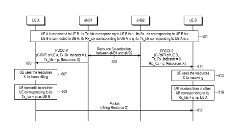
for D2D communication, and transmission of the transmission and reception
indicator,
the index, and resource information for the D2D communication on a control
channel
to the UE, and a transceiver configured to communicate with at least one UE
under
control of the controller. The D2D communication is performed between the UE
and
the other UE by performing a transmission operation or a reception operation
between
the UE and the other UE determined by the index in resources indicated by the
resource information according to the transmission role or the reception role
indicated
by the transmission and reception indicator.
[11] In accordance with another aspect of the present disclosure, a method
for performing
D2D communication is provided. The method includes being assigned a network
temporary ID for D2D communication during D2D connection setup with a BS by a
UE, receiving resource information for the D2D communication on a control
channel
masked with the network temporary ID by the UE, and performing a transmission
operation or a reception operation to or from another UE determined based on
the
network temporary ID in resources indicated by the resource information by the
UE.
[12] In accordance with another aspect of the present disclosure, a method
for performing
D2D communication is provided. The method includes assigning a network
temporary
ID for D2D communication to a UE during D2D connection setup with the UE by a
BS, and transmitting resource information for the D2D communication on a
control
channel masked with the network temporary ID to the UE by the BS. The D2D com-
munication is performed between the UE and another UE by a transmission
operation
or a reception operation between the UE and the other UE determined based on
the
network temporary ID in resources indicated by the resource information.
[13] In accordance with another aspect of the present disclosure, a UE for
performing
D2D communication is provided. The UE includes a transceiver configured to
perform
D2D communication with another UE through a direct communication link, and a
controller configured to control a network temporary ID for D2D communication
to be
assigned during D2D connection setup with a BS, and to control reception of
resource
information for the D2D communication on a control channel masked with the
network
temporary ID and performing of a transmission operation or a reception
operation to or
from another UE determined based on the network temporary ID in resources
indicated
by the resource information.
[14] In accordance with another aspect of the present disclosure, a BS for
performing
D2D communication is provided. The BS includes a controller configured to
control
assignment of a network temporary ID for D2D communication to a UE during D2D
connection setup with the UE and transmission of resource information for the
D2D
communication on a control channel masked with the network temporary ID to the
UE,
and a transceiver configured to communicate with at least one UE under control
of the
CA 02916956 2015-12-29
WO 2014/209077 PCT/KR2014/005782
4
controller. The D2D communication is performed between the UE and another UE
by
a transmission operation or a reception operation between the UE and the other
UE de-
termined based on the network temporary ID in resources indicated by the
resource in-
formation.
[15] In accordance with another aspect of the present disclosure, a method
for performing
D2D communication is provided. The method includes being assigned a UE pair ID
for
D2D communication during D2D connection setup with a BS by a UE, receiving the
UE pair ID and resource information for the D2D communication on a control
channel
by the UE, the control channel being masked with a network temporary ID
reserved for
D2D communication, and performing a transmission operation or a reception
operation
to or from another UE determined based on the UE pair ID in resources
indicated by
the resource information by the UE. The network temporary ID is the same for
all D2D
connections.
[16] In accordance with another aspect of the present disclosure, a method
for performing
D2D communication is provided. The method includes assigning a UE pair ID for
D2D communication to a UE during D2D connection setup with the UE by a BS, and
transmitting the UE pair ID and resource information for the D2D communication
on a
control channel to the UE by the BS, the control channel being masked with a
network
temporary ID reserved for D2D communication. The D2D communication is
performed between the UE and another UE by a transmission operation or a
reception
operation between the UE and the other UE based on the UE pair ID in resources
indicated by the resource information. The network temporary ID is the same
for all
D2D connections.
[17] In accordance with another aspect of the present disclosure, a UE for
performing
D2D communication is provided. The UE includes a transceiver configured to
perform
D2D communication with another UE on a direct communication link, and a
controller
configured to control a UE pair ID for D2D communication to be allocated to
the UE
during D2D connection setup with a BS, to control reception of the UE pair ID
and
resource information for the D2D communication on a control channel, the
control
channel being masked with a network temporary ID reserved for D2D
communication,
and to control performing of a transmission operation or a reception operation
to or
from another UE determined based on the UE pair ID in resources indicated by
the
resource information. The network temporary ID is the same for all D2D
connections.
[18] In accordance with another aspect of the present disclosure, a BS for
performing
D2D communication is provided. The BS includes a controller configured to
control
assignment of a UE pair ID for D2D communication to a UE during D2D connection
setup with the UE, and transmission of the UE pair ID and resource information
for the
D2D communication on a control channel to the UE, the control channel being
masked
CA 02916956 2015-12-29
WO 2014/209077 PCT/KR2014/005782
with a network temporary ID reserved for D2D communication, and a transceiver
configured to communicate with at least one UE under control of the
controller. The
D2D communication is performed between the UE and another UE by a transmission
operation or a reception operation between the UE and the other UE based on
the UE
pair ID in resources indicated by the resource information. The network
temporary ID
is the same for all D2D connections.
[19] In accordance with another aspect of the present disclosure, a method
for performing
D2D communication is provided. The method includes receiving a network
temporary
ID of another UE for D2D communication during D2D connection setup with a BS
by
a UE, receiving information about the other UE and resource information for
the D2D
communication with the other UE on a control channel by the UE, the control
channel
being masked with a network temporary ID of a UE to play a transmission role
or a
reception role in the D2D communication, and performing a transmission
operation or
a reception operation to or from the other UE based on the network temporary
ID used
in masking the control channel and the information about the other UE in
resources
indicated by the resource information by the UE. The network temporary ID is
different for each UE.
[20] In accordance with another aspect of the present disclosure, a method
for performing
D2D communication is provided. The method includes transmitting a network
temporary ID of another UE for D2D communication during D2D connection setup
with a UE by a BS, and transmitting information about the other UE and
resource in-
formation for the D2D communication with the other UE on a control channel to
the
UE by the BS, the control channel being masked with a network temporary ID of
a UE
to play a transmission role or a reception role in the D2D communication. The
D2D
communication is performed between the UE and the other UE by a transmission
operation or a reception operation between the UE and the other UE based on
the
network temporary ID used in masking the control channel and the information
about
the other UE in resources indicated by the resource information. The network
temporary ID is different for each UE.
[21] In accordance with another aspect of the present disclosure, a UE for
performing
D2D communication is provided. The UE includes a transceiver configured to
perform
D2D communication with another UE on a direct communication link, and a
controller
configured to control reception of a network temporary ID of the other UE for
the D2D
communication during D2D connection setup with a BS, reception of information
about the other UE and resource information for the D2D communication with the
other UE on a control channel masked with a network temporary ID of a UE to
play a
transmission role or a reception role in the D2D communication, and performing
of a
transmission operation or a reception operation to or from the other UE based
on the
CA 02916956 2015-12-29
WO 2014/209077 PCT/KR2014/005782
6
network temporary ID used in masking the control channel and the information
about
the other UE in resources indicated by the resource information. The network
temporary ID is different for each UE.
[22] In accordance with another aspect of the present disclosure. a BS for
performing
D2D communication is provided. The BS includes a controller configured to
control
transmission of a network temporary ID of another UE for D2D communication
during
D2D connection setup with a UE, and transmission of information about the
other UE
and resource information for the D2D communication with the other UE on a
control
channel to the UE, the control channel being masked with a network temporary
ID of a
UE to play a transmission role or a reception role in the D2D communication,
and a
transceiver configured to communicate with at least one UE under control of
the
controller. The D2D communication is performed between the UE and the other UE
by
a transmission operation or a reception operation between the UE and the other
UE
based on the network temporary ID used in masking the control channel and the
in-
formation about the other UE in resources indicated by the resource
information. The
network temporary ID is different for each UE.
[23] In accordance with another aspect of the present disclosure, a method
for allocating
resources for Device-to-Device (D2D) communication is provide. The method
includes
requesting resources for D2D communication by transmitting a D2D buffer status
report or a D2D scheduling request to a Base Station (BS); and receiving
resources for
D2D communication from BS, wherein the resources for D2D communication is
received on a control channel in a downlink (DL) subframe corresponding to an
uplink
(UL) subframe reserved for D2D communication, or on a control channel using
control
information format for D2D communication, or on a control channel with Cyclic
Re-
dundancy Check (CRC) masked using a radio network terminal identifier (RNTI)
assigned to a User Equipment (UE) for D2D communication.
[24] In accordance with another aspect of the present disclosure, a method
for allocating
resources for Device-to-Device (D2D) communication is proved. The method
includes
receiving a buffer status report or a scheduling request from a User Equipment
(UE);
determining whether the buffer status report or the scheduling request is for
D2D com-
munication, allocating resources for D2D communication if the buffer status
report or
the scheduling request is for D2D communication and transmitting the allocated
resources for D2D communication to the UE, wherein the resources for D2D commu-
nication is transmitted on a control channel in a downlink (DL) subframe corre-
sponding to an uplink (UL) subframe reserved for D2D communication, or on a
control
channel using control information format for D2D communication or on a control
channel with Cyclic Redundancy Check (CRC) masked using a radio network
terminal
identifier (RNTI) assigned to a User Equipment (UE) for D2D communication.
7
[25] In accordance with another aspect of the present disclosure, a User
Equipment (UE) for
allocating resources for Device-to-Device (D2D) communication is proved. The
UE includes
a transceiver configured to perform D2D communication with another UE through
a direct
communication link; and a controller configured to control for requesting
resources for D2D
communication by transmitting a D2D buffer status report or a D2D scheduling
request to a
Base Station (BS) and for receiving resources for D2D communication from BS,
wherein the
resources for D2D communication is received on a control channel in a downlink
(DL)
subframe corresponding to an uplink (UL) subframe reserved for D2D
communication, or on
a control channel using control information format for D2D communication, or
on a control
channel with Cyclic Redundancy Check (CRC) masked using a radio network
terminal
identifier (RNTI) assigned to a User Equipment (UE) for D2D communication.
[26] In accordance with another aspect of the present disclosure, a Base
Station (BS) for
allocating resources for Device-to-Device (D2D) communication is proved. The
BS includes
a controller configured to control for receiving a buffer status report or a
scheduling request
from a User Equipment (UE), determining whether the buffer status report or
the scheduling
request is for D2D communication, allocating resources for D2D communication
if the
buffer status report or the scheduling request is for D2D communication and
transmitting the
allocated resources for D2D communication to the UE and a transceiver
configured to
perform communication with the UE by controlling of the controller, wherein
the resources
for D2D communication is transmitted on a control channel in a downlink (DL)
subframe
corresponding to an uplink (UL) subframe reserved for D2D communication, or on
a control
channel using control information format for D2D communication or on a control
channel
with Cyclic Redundancy Check (CRC) masked using a radio network terminal
identifier
(RNTI) assigned to the UE for D2D communication.
According to an aspect of the present invention there is provided a method for
device-to-
device (D2D) communication, the method comprising:
transmitting, by a user equipment (UE), a D2D indication message to a base
station (BS);
in response to the D2D indication message, receiving, from the BS, a message
including a
radio network terminal identifier (RNTI) for D2D communication, the RNTI for
D2D
communication being assigned by the BS to the UE;
transmitting, to the BS, a buffer status report for D2D communication to
request resources
Date Recue/Date Received 2021-01-15
7a
for D2D communication; and
receiving information on resources for D2D communication from the BS using the
RNTI for
D2D communication,
wherein the buffer status report for D2D communication includes a destination
ID for D2D
communication, a logical channel group ID, and a buffer size, and
wherein the buffer status report for D2D communication is identified by media
access
control protocol data unit (MAC PDU) subheaders with a logical channel
identifier (LCID) and a
LCID value indicating the buffer status report for D2D communication is
different from a LCID
value indicating a buffer status report for uplink transmission to the BS.
According to another aspect of the present invention there is provided a
method for device-
to-device (D2D) communication, the method comprising:
receiving, by a base station (BS), a D2D indication message from a user
equipment (UE);
assigning a radio network terminal identifier (RNTI) for D2D communication to
the UE, and
in response to the D2D indication message, transmitting, to the UE, a message
including the RNTI
for D2D communication;
receiving, from the UE, a buffer status report for D2D communication to
request resources
for D2D communication;
determining that the UE has data for D2D communication based on the buffer
status report
for D2D communication; and
allocating, to the UE, resources for D2D communication using the RNTI for D2D
communication,
wherein the buffer status report for D2D communication includes a destination
ID for D2D
communication, a logical channel group ID, and a buffer size, and
wherein the buffer status report for D2D communication is identified by media
access
control protocol data unit (MAC PDU) subheaders with a logical channel
identifier (LCID) and a
LCID value indicating the buffer status report for D2D communication is
different from a LCID
value indicating a buffer status report for uplink transmission to the BS.
According to a further aspect of the present invention there is provided an
apparatus for
device-to-device (D2D) communication, the apparatus comprising:
Date Recue/Date Received 2021-01-15
7b
a transceiver configured to perform D2D communication with another apparatus
through a
direct communication link; and
a controller configured to:
transmit a D2D indication message to a base station (BS),
in response to the D2D indication message, receive, from the BS, a message
including a
radio network terminal identifier (RNTI) for D2D communication, the RNTI for
D2D
communication being assigned by the BS to the UE,
transmit, to the BS, a buffer status report for D2D communication to request
resources for
D2D communication, and
receive information on resources for D2D communication from the BS using the
RNTI for
D2D communication,
wherein the buffer status report for D2D communication includes a destination
ID for D2D
communication, a logical channel group ID, and a buffer size, and
wherein the buffer status report for D2D communication is identified by media
access
control protocol data unit (MAC PDU) subheaders with a logical channel
identifier (LCID) and a
LCID value indicating the buffer status report for D2D communication is
different from a LCID
value indicating a buffer status report for uplink transmission to the BS.
According to a further aspect of the present invention there is provided an
apparatus for
device-to-device (D2D) communication, the apparatus comprising:
a controller configured to:
receive a D2D indication message from a user equipment (UE),
assign a radio network terminal identifier (RNTI) for D2D communication to the
UE, and in
response to the D2D indication message, transmit, to the UE, a message
including the RNTI for D2D
communication,
receive a buffer status report for D2D communication for requesting resources
for D2D
communication,
determine that the UE has data for D2D communication based on the buffer
status report for
D2D communication, and
allocate resources for D2D communication using the RNTI for D2D communication
to the
UE; and
a transceiver configured to perform communication with the UE,
Date Recue/Date Received 2021-01-15
7c
wherein the buffer status report for D2D communication includes a destination
ID for D2D
communication, a logical channel group ID, and a buffer size, and
wherein the buffer status report for D2D communication is identified by media
access
control protocol data unit (MAC PDU) subheaders with a logical channel
identifier (LCID) and a
LCID value indicating the buffer status report for D2D communication is
different from a LCID
value indicating a buffer status report for uplink transmission to the BS.
[27] Other aspects, advantages, and salient features of the disclosure will
become apparent to
those skilled in the art from the following detailed description, which, taken
in conjunction
with the annexed drawings, discloses various embodiments of the present
disclosure.
Brief Description of Drawings
[28] The above and other aspects, features, and advantages of certain
embodiments of the
present disclosure will be more apparent from the following description taken
in conjunction
with the accompanying drawings, in which:
[29] FIG. 1 illustrates a Device-to-Device (D2D) communication environment
according to the
related art;
[30] FIG. 2 illustrates a case in which a plurality of User Equipment (UE)
pairs connected
Date Recue/Date Received 2021-01-15
CA 02916956 2015-12-29
WO 2014/209077 PCT/KR2014/005782
8
to an evolved Node B (eNB) participate in D2D communication according to an em-
bodiment of the present disclosure;
[31] FIG. 3 illustrates a method for allocating resources for D2D
communication
according to an embodiment of the present disclosure;
[32] FIG. 4 illustrates another method for allocating resources for D2D
communication
according to an embodiment of the present disclosure;
[33] FIG. 5 illustrates a third method for allocating resources for D2D
communication
according to an embodiment of the present disclosure;
[34] FIGS. 6 and 7 illustrate a method for allocating resources for D2D
communication
between cells according to an embodiment of the present disclosure;
[35] FIGS. 8 and 9 illustrate a method for allocating resources for D2D
communication
within a cell according to an embodiment of the present disclosure;
[36] FIG. 10 illustrates a method for allocating a transmission index and a
reception index
in allocating resources for D2D communication between cells according to an em-
bodiment of the present disclosure;
1371 FIG. 11 illustrates another method for allocating a transmission index
and a reception
index in allocating resources for D2D communication between cells according to
an
embodiment of the present disclosure;
[38] FIG. 12 illustrates a method for allocating a transmission index and a
reception index
in allocating resources for D2D communication within a cell according to an em-
bodiment of the present disclosure;
[39] FIG. 13 illustrates another method for allocating a transmission index
and a reception
index in allocating resources for D2D communication within a cell according to
an em-
bodiment of the present disclosure;
[40] FIGS. 14 and 15 are diagrams illustrating signal flows for allocating
a connection
index instead of a Tx index or an Rx index for D2D communication according to
an
embodiment of the present disclosure;
[41] FIG. 16 illustrates an example of allocating Cell Radio Network
Temporary
Identifiers (C-RNTIs) and UE-pair C-RNTIs according to an embodiment of the
present disclosure;
[42] FIG. 17 illustrates an example of reusing a C-RNTI address space for
UE-pair C-
RNTIs according to an embodiment of the present disclosure;
[43] FIGS. 18a and 18b illustrate methods for allocating resources for
transmission of a
D2D Buffer Status Report according to an embodiment of the present disclosure;
[44] FIG. 19 illustrates an example of distinguishing resources for
communication
between a UE pair from resources for other UEs within the coverage area of an
eNB
according to an embodiment of the present disclosure;
11451 FIG. 20 illustrates an example of distinguishing resources for
communication
CA 02916956 2015-12-29
WO 2014/209077 PCT/KR2014/005782
9
between a UE pair from resources for communication between a UE of the UE pair
and an eNB according to an embodiment of the present disclosure;
1461 FIG. 21 illustrates an example of distinguishing resources for
communication
between one UE pair from resources for communication between another UE pair
according to an embodiment of the present disclosure;
[47] FIG. 22 illustrates a method for identifying transmission resources
and reception
resources in the case of unidirectional communication according to an
embodiment of
the present disclosure;
[48] FIG. 23 illustrates a method for identifying transmission resources
and reception
resources in the case of bidirectional communication according to an
embodiment of
the present disclosure;
[49] FIG. 24 illustrates a method for identifying transmission resources
and reception
resources in the case of bidirectional communication according to an
embodiment of
the present disclosure;
[50] FIG. 25 illustrates a method for allocating a UE index (UE_idx) and a
UE-pair C-
RNTI (C-RNTILJE pair) in allocating resources for D2D communication within a
cell
according to an embodiment of the present disclosure;
[51] FIG. 26 is a diagram illustrating a signal flow for allocating a
transmission UE-pair
C-RNTI (Tx C-RNTILJE pan) and a reception UE-pair C-RNTI (Rx C-RNTILJE pan)
according to an embodiment of the present disclosure;
[52] FIG. 27 illustrates an example of distinguishing resources for
communication
between a UE pair from resources for other UEs within the coverage area of an
eNB
according to an embodiment of the present disclosure;
[53] FIG. 28 illustrates an example of distinguishing resources for UE pair
commu-
nication from resources for communication between the UEs of a UE pair and an
eNB
according to an embodiment of the present disclosure;
[54] FIG. 29 illustrates an example of distinguishing resources for UE pair
commu-
nication from resources for other UE pair communication according to an
embodiment
of the present disclosure;
[55] FIG. 30 illustrates a method for allocating a UE index and a UE pair
ID in allocating
resources for D2D communication within a cell according to an embodiment of
the
present disclosure;
[56] FIG. 31 illustrates an operation for allocating a transmission UE pair
ID and a
reception UE pair ID according to an embodiment of the present disclosure;
1571 FIG. 32 illustrates a method for using a unified C-RNTI for direct
communication
according to an embodiment of the present disclosure;
[58] FIG. 33 illustrates an example of using a unified C-RNTI and a
transmission and
reception index for direct communication according to an embodiment of the
present
CA 02916956 2015-12-29
WO 2014/209077 PCT/KR2014/005782
disclosure;
[59] FIG. 34 is a diagram illustrating a signal flow for allocating a
transmission and
reception index in allocating resources for D2D communication within a cell
according
to an embodiment of the present disclosure;
[60] FIG. 35 is a diagram illustrating a signal flow for allocating
transmission and
reception indexes to UEs according to an embodiment of the present disclosure;
[61] FIG. 36 illustrates an example of distinguishing resources for UE pair
commu-
nication from other resources within the coverage area of an eNB according to
an em-
bodiment of the present disclosure;
[62] FIG. 37 illustrates an example of distinguishing resources for
communication
between a UE pair from resources for communication between a UE of the UE pair
and an eNB according to an embodiment of the present disclosure;
[63] FIG. 38 illustrates an example of distinguishing resources for
communication
between one UE pair from resources for communication between another UE
according to an embodiment of the present disclosure;
1641 FIG. 39 illustrates a method for using a unified C-RNTI and a
transmission and
reception index for direct communication according to an embodiment of the
present
disclosure;
[65] FIG. 40 illustrates an example of distinguishing resources for
communication
between a UE pair from other resources within the coverage area of an eNB
according
to an embodiment of the present disclosure;
[66] FIG. 41 illustrates an example of distinguishing resources for
communication
between a UE pair from resources for communication between an eNB and a UE of
the
UE pair according to an embodiment of the present disclosure;
[67] FIG. 42 illustrates an example of distinguishing resources for
communication
between one UE pair from resources for communication between another UE pair
according to an embodiment of the present disclosure;
[68] FIG. 43 illustrates an operation for allocating and exchanging a
unified C-RNTI
according to an embodiment of the present disclosure;
[69] FIG. 44 illustrates an example of distinguishing resources for UE pair
commu-
nication from other resources within the coverage area of an eNB according to
an em-
bodiment of the present disclosure;
[70] FIG. 45 illustrates an example of distinguishing resources for
communication
between a UE pair from resources for communication between an eNB and a UE of
the
UE pair according to an embodiment of the present disclosure;
1711 FIG. 46 illustrates an example of distinguishing resources for UE pair
commu-
nication from resources for other UE pair communication according to an
embodiment
of the present disclosure;
CA 02916956 2015-12-29
WO 2014/209077 PCT/KR2014/005782
11
[72] FIG. 47 illustrates an example of distinguishing resources for UE pair
commu-
nication from other resources within the coverage area of an eNB according to
an em-
bodiment of the present disclosure;
[73] FIG. 48 illustrates an example of distinguishing resources for
communication
between a UE pair from resources for communication between an eNB and a UE of
the
UE pair according to an embodiment of the present disclosure;
[74] FIG. 49 illustrates an example of distinguishing resources for
communication
between one UE pair from resources for communication between another UE pair
according to an embodiment of the present disclosure;
[75] FIG. 50 is a block diagram of an eNB according to an embodiment of the
present
disclosure; and
[76] FIG. 51 is a block diagram of a UE according to an embodiment of the
present
disclosure.
[77] Throughout the drawings, like reference numerals will he understood to
refer to like
parts, components, and structures.
Mode for the Invention
[78] The following description with reference to the accompanying drawings
is provided
to assist in a comprehensive understanding of various embodiments of the
present
disclosure as defined by the claims and their equivalents. It includes various
specific
details to assist in that understanding but these are to be regarded as merely
exemplary.
Accordingly, those of ordinary skilled in the art will recognize that various
changes
and modifications of the various embodiments described herein can be made
without
departing from the scope and spirit of the present disclosure. In addition,
descriptions
of well-known functions and constructions may be omitted for clarity and
conciseness.
[79] The terms and words used in the following description and claims are
not limited to
the bibliographical meanings, but, are merely used by the inventor to enable a
clear and
consistent understanding of the present disclosure. Accordingly, it should be
apparent
to those skilled in the art that the following description of various
embodiments of the
present disclosure is provided for illustration purpose only and not for the
purpose of
limiting the present disclosure as defined by the appended claims and their
equivalents.
[80] It is to be understood that the singular forms "a," "an." and "the"
include plural
referents unless the context clearly dictates otherwise. Thus, for example,
reference to
"a component surface" includes reference to one or more of such surfaces.
[81] By the term "substantially" it is meant that the recited
characteristic, parameter, or
value need not be achieved exactly, but that deviations or variations,
including for
example, tolerances, measurement error, measurement accuracy limitations and
other
factors known to those of skill in the art, may occur in amounts that do not
preclude the
CA 02916956 2015-12-29
WO 2014/209077 PCT/KR2014/005782
12
effect the characteristic was intended to provide.
[82] A Base Station (BS) is an entity that communicates with a User
Equipment (UE).
The term BS may be replaced with Node B, evolved Node B (eNB or eNode B),
Access Point (AP), and the like.
[83] A UE is an entity that communicates with a BS. The term UE may be
replaced with
Mobile Station (MS), Mobile Equipment (ME), device, terminal, and the like.
[84] FIG. 1 illustrates a Device-to-Device (D2D) communication environment
according
to the related art.
[85] Referring to FIG. 1, a pair of a first UE (UE1) and a second UE (UE2)
are connected
to an eNB and also to each other for direct communication. UE1 and UE2 com-
municate with the eNB using a DownLink (DL) frequency Fl and an UpLink (UL)
frequency F2 in a FDD (Frequency Division Duplex) system. The UL frequency F2
is
also used for D2D communication between UE1 and UE2. Resources of the UL
frequency F2 are controlled by the eNB. In a TDD (Time Division Duplexed)
system,
UE1 and UE2 communicate with the eNB using a frequency Fl comprising of UL and
DL time slots wherein UL time slots are used by UE 1 and UE 2 to transmit to
eNB
and DL time slots are used by UE1 and UE2 to receive from eNB. The UL time
slots
are also used for D2D communication between UE1 and UE2. It is to be noted
that UE
may also communicate with multiple UEs concurrently.
[86] FIG. 2 illustrates a case in which a plurality of UE pairs connected
to an eNB par-
ticipates in D2D communication according to an embodiment of the present
disclosure.
[87] Referring to FIG. 2, all of UE1, UE2, a third UE (UE3), a fourth UE
(UE4). and a
fifth UE (UE5) communicate with the eNB using the DL frequency D1 and the UL
frequency F2 in a FDD (Frequency Division Duplex) system. As described before,
UE
pairs, herein, a UE1-UE2 pair and a UE4-UE5 pair perform D2D communication
using
the UL frequency F2. In a TDD (Time Division Duplexed) system, UE(s) com-
municate with the eNB using a frequency Fl comprising of UL and DL time slots
wherein UL time slots is used by UE(s) to transmit to eNB and DL time slots
are used
by UE(s) to receive from eNB. The UL time slots are also used for D2D commu-
nication between UE1-UE2 and UE4-UE5.
[88] In this case, there is a need for a method for signaling Transmission
(Tx) resources
and/or Reception (Rx) resources for the UEs involved in D2D communication, a
method for identifying a Tx role and an Rx role between the UEs during D2D
commu-
nication, a method for distinguishing Tx resources from Rx resources for each
UE.
Embodiments of the present disclosure provide these methods.
[89] Embodiment 1
[90] A method for allocating resources for D2D transmission in one
embodiment is
described below.
CA 02916956 2015-12-29
WO 2014/209077 PCT/KR2014/005782
13
[91] A UE within the coverage area of a network may participate in D2D
communication
and may also communicate with an eNB. The UE requests resources for D2D commu-
nication to an eNB of a serving cell within the network coverage area. In
order to
allocate the resources, the eNB determines whether the UE has requested the
resources
for D2D communication or for UL transmission to the eNB. The resources for D2D
communication and the resources for UL transmission to the eNB are allocated
to the
UE through a DL control channel, Physical Downlink Control Channel (PDCCH) or
Enhanced PDCCH (EPDCCH). When the UE receives and decodes the DL control
channel (the PDCCH or the EPDCCH) masked with its IDentifier (ID), then the UE
determines whether the allocated resources are for D2D communication or for UL
transmission to the eNB.
[92] Hereinbelow, three methods for allocating resources for D2D
transmission according
to embodiments of the present disclosure will be described.
[93] FIG. 3 illustrates a method for allocating resources for D2D
transmission according
to an embodiment of the present disclosure.
1941 Resources for UL transmission to the eNB and resources for D2D
communication are
indicated through a control channel transmitted by eNB in different DL
subframes. A
UE is aware of a DL subframe indicating resources for UL transmission to the
eNB
and a DL subframe indicating resources for D2D communication. Alternately
Resources for UL transmission to the eNB and resources for D2D communication
may
be indicated through a control channel transmitted by eNB in same DL subframe.
UE
detemiines that resources are for D2D communication if the resources is
indicated in
control channel belong to set of resources reserved in UL subframe
corresponding to
DL subframe in which control channel is received. The UE uses a single Cell
Radio
Network Temporary Identity (C-RNTI) to determine the resources for each type
of
communication.
[95] Referring to FIG. 3, the UE is in a connected state and assigned a C-
RNTI by the
eNB. If the UE wants to transmit control and/or data packets through a D2D
commu-
nication link, the UE transmits a D2D Buffer Status Report (BSR) to the eNB in
operation 301. The D2D BSR is different from a general BSR wherein the UE
sends
the general BSR to eNB to request resources for UL transmission to eNB. A
Logical
Channel ID (LCID) identifies the D2D BSR from a general BSR. ALCID is newly
reserved to indicate the D2D BSR. The LCID may be included in the D2D BSR.
Alter-
natively, the LCID may be included in a Medium Access Control (MAC) subheader
in-
dicating a MAC control element having the D2D BSR in a MAC Packet Data Unit
(PDU). The D2D BSR may also include a destination ID. The destination ID is
the ID
of a destination to which the UE wants to transmit control and/or data packets
through
the D2D communication link. The destination ID may be a unicast address of
another
CA 02916956 2015-12-29
WO 2014/209077 PCT/KR2014/005782
14
UE, group cast address of a group of UEs, or broadcast address. The D2D BSR
may
also include buffer size and logical channel group ID. Multiple logical
channels are
typically grouped together and buffer status of group of these logical
channels is sent
using one buffer status report.
[96] If Physical Uplink Control Channel (PUCCH) resources are available for
transmission of the D2D BSR, the resources for the D2D BSR may be obtained
using a
general method such as transmitting a scheduling request to the eNB.
Alternately the
resources for the D2D BSR may be obtained by transmitting a random access
preamble
to the eNB on a Random Access CHannel (RACH). D2D BSR may also be sent in
resources already allocated by eNB for UL transmission to eNB.
[97] Upon receipt of the BSR, the eNB in operation 303 determines whether
the BSR is
for D2D communication or for UL transmission to eNB. This determination is
done
using the LCID. lithe BSR is a D2D BSR then ENB allocates resources for D2D
transmission in operation 305 and transmits a grant for D2D transmission on a
PDCCH
or EPDCCH in a DL subframe corresponding to a UL subframe reserved for D2D
communication in operation 307. An Control Information format carrying D2D
resource information is the same as or different from a control information
format
carrying resource information for transmission of a UE to an eNB or for
reception from
eNB. The Cyclic Redundancy Check (CRC) of PDCCH or EPDCCH carrying control
information is masked with the C-RNTI.
1981 If the UE transmits a Scheduling Assignment (SA) for the D2D
communication link
in addition to a data packet, upon receipt of the D2D BSR, the eNB may
allocate
resources for transmission of both the SA and the data packet and indicate the
allocated
resources using the same or different PDCCHs or EPDCCHs. Alternatively or addi-
tionally, upon receipt of the D2D BSR, the eNB may allocate resources for
transmitting the SA only. The resources for the data packet may be fixed
relative to the
location of the SA and/or resources for the SA.
[99] In an alternate embodiment of method illustrated in FIG. 3, instead of
BSR, a D2D
scheduling request can be transmitted on PUCCH wherein the PUCCH resources are
reserved and/or assigned to UE for D2D SR transmission. eNB determines that UE
needs resources for D2D communication on receiving the D2D scheduling request
in
the PUCCH resources reserved and/or assigned to UE for D2D SR transmission.
[100] FIG. 4 illustrates another method for allocating resources for D2D
transmission
according to an embodiment of the present disclosure.
[101] Control information format delivered on a control channel indicating
resources for
communication with an eNB and control information format delivered on a
control
channel indicating resources for D2D communication may have different formats.
The
control information format of the control channel indicating resources for D2D
com-
CA 02916956 2015-12-29
WO 2014/209077 PCT/KR2014/005782
munication may be designed such that the size of the control information
format is
different from the size of general control information format, so that when a
UE
receives and decodes the control channel, the UE may determine whether the
control
information indicates resources for D2D communication or not.
[102] Referring to FIG. 4, a UE is in a connected state and assigned a C-
RNTI by an eNB.
If the UE wants to transmit control and/or data packets through a D2D
communication
link, the UE transmits a D2D BSR to the eNB in operation 401. The D2D BSR is
different from a general BSR wherein the UE sends the general BSR to eNB to
request
resources for UL transmission to eNB. The D2D BSR is distinguished from a
general
BSR by an LCID. The LCID is reserved to indicate the D2D BSR. The LCID may be
included in the D2D BSR. Alternatively or additionally, the LCID may be
included in
a MAC subheader indicating a MAC control element with the D2D BSR in a MAC
PDU. The D2D BSR may also include a destination ID. The destination ID is the
ID of
a destination to which the LIE wants to transmit control and/or data packets
through the
D2D communication link. The destination ID may be a unicast address of another
UE,
group cast address of a group of UEs, or broadcast address. The D2D BSR may
also
include buffer size and logical channel group ID. Multiple logical channels
are
typically grouped together and buffer status of group of these logical
channels is sent
using one buffer status report.
[103] If PUCCH resources are available for transmission of the D2D BSR, the
resources
for the D2D BSR may be obtained using a general method such as transmitting a
scheduling request to the eNB. Alternately the resources for the D2D BSR may
be
obtained by transmitting a random access preamble to the eNB on an RACH. ).
D2D
BSR may also be sent in resources already allocated by eNB for UL transmission
to
eNB.
[104] Upon receipt of the BSR, the eNB in operation 403 determines whether
the BSR is
for D2D communication or for UL transmission to eNB. This determination is
done
using the LCID. If the BSR is a D2D BSR the eNB allocates resources for D2D
transmission in operation 405 and transmits a grant for D2D transmission on a
PDCCH
or EPDCCH in operation 407. A control informationformat carrying D2D resource
in-
formation is different from a control information format carrying resource
information
for transmission of a UE to an eNB or for reception from eNB. The CRC of PDCCH
or
EPDCCH carrying control information is masked with the C-RNTI.
[105] If the UE transmits an SA for the D2D communication link in addition
to a data
packet, upon receipt of the D2D BSR, the eNB may allocate resources for
transmission
of both the SA and the data packet and may indicate the allocated resources
using the
same PDCCH or EPDCCH or different PDCCHs or EPDCCHs. Alternatively or addi-
tionally, upon receipt of the D2D BSR, the eNB may allocate resources for
CA 02916956 2015-12-29
WO 2014/209077 PCT/KR2014/005782
16
transmission of the SA only. The resources for the data packet may be fixed
relative to
the location of the SA and/or resources for the SA.
[1061 In an alternate embodiment of method illustrated in FIG. 4, instead
of BSR, a D2D
scheduling request can be transmitted on PUCCH wherein the PUCCH resources are
reserved and/or assigned for D2D SR transmission. eNB determines that UE needs
resources for D2D communication on receiving the D2D scheduling request in the
PUCCH resources reserved and/or assigned to UE for D2D SR transmission.
[1071 FIG. 5 illustrates a third method for allocating resources for D2D
transmission
according to an embodiment of the present disclosure.
[108] Different C-RNTIs may be assigned to a UE for communication with an
eNB and
D2D communication. Therefore, the eNB uses the one or more C-RNTIs assigned
for
D2D communication on a control channel carrying resources for D2D
communication
and the one or more C-RNTIs assigned for communication between the UE and the
eNB on a control channel carrying resources for communication between the UE
and
the eNB.
[109] Referring to FIG. 5, a UE is in a connected state and assigned one or
more C-RNTIs
by an eNB for communication with eNB. If the UE wants to transmit a signal
through
a D2D communication link, the UE transmits a D2D communication request
message(or a D2D communication interest indication message or UE assistance in-
formation message with D2D communication interest indication wherein the
interest
indication may indicate that UE is interested in D2D communication or it may
indicate
that UE is interested in transmission for D2D communication or it may indicate
that
UE is interested in reception for D2D communication or it may indicate that UE
is in-
terested in both transmission and reception for D2D communication) to the eNB
in
operation 501. The eNB assigns a D2D Radio Network Temporary Identifier (RNTI)
(D2D-RNT1) to the UE in response to the D2D communication request message (or
D2D communication interest indication message or UE assistance information
message with D2D communication interest indication) in operation 503. In one
em-
bodiment the D2D communication response message in operation 503 may be a RRC
connection reconfiguration message. If the UE wants to transmit control and/or
data
packets through a D2D communication link,the UE transmits a D2D BSR to the eNB
in operation 505. The D2D BSR is different from a general BSR transmitted to
the
eNB for requesting a grant for communication between the UE and the eNB to the
eNB. An LCID distinguishes the D2D BSR from the general BSR. The LCID is
reserved to indicate the D2D BSR. The LCID may be included in the D2D BSR.
Alter-
natively or additionally, the LCID may be included in a MAC subheader which
indicates a MAC control element having the D2D BSR in a MAC PDU. The D2D BSR
may also include a destination ID. The destination ID is the ID of a
destination to
CA 02916956 2015-12-29
WO 2014/209077 PCT/KR2014/005782
17
which the UE wants to transmit control and/or data packets through the D2D
commu-
nication link. The destination ID may be a unicast address of another UE,
group cast
address of a group of UEs, or broadcast address. . The D2D BSR may also
include
buffer size and logical channel group ID. Multiple logical channels are
typically
grouped together and buffer status of group of these logical channels is sent
using one
buffer status report.
[110] If PUCCH resources are available for transmission of the D2D BSR, the
resources
for the D2D BSR may be obtained using a general method such as transmitting a
scheduling request to the eNB. Alternately the resources for the D2D BSR may
be
obtained by transmitting a random access preamble to the eNB on an RACH. D2D
BSR may also be sent in resources already allocated by eNB for UL transmission
to
eNB.
[111] Upon receipt of the BSR. the eNB in operation 507 determines whether
the BSR is
for D2D communication or for UL transmission to eNB. This determination is
done
using the LCID. lithe BSR is a D2D BSR the eNB allocates resources for D2D
transmission in operation 509 and transmits a grant for D2D transmission on a
PDCCH
or EPDCCH in operation 511. A control information format carrying D2D resource
in-
formation may be same or different from a control information format carrying
resource information for transmission of a UE to an eNB. The CRC of PDCCH or
EPDCCH carrying control information is masked with the D2D-RNTI.
[112] If the UE transmits an SA for the D2D communication link in addition
to a data
packet, upon receipt of the D2D BSR, the eNB may allocate resources for
transmission
of both the SA and the data packet and may indicate the allocated resources
using the
same PDCCH or EPDCCH or different PDCCHs or EPDCCHs. Alternatively or addi-
tionally, upon receipt of the D2D BSR, the eNB may allocate resources for
transmission of the SA only. The resources for the data packet may be fixed
relative to
the location of the SA and/or resources of the SA.
[113] In an alternate embodiment of method illustrated in FIG. 5, instead
of BSR, a D2D
scheduling request can be transmitted on PUCCH wherein the PUCCH resources are
reserved and/or assigned for D2D SR transmission. eNB determines that UE needs
resources for D2D communication on receiving the D2D scheduling request in the
PUCCH resources reserved and/or assigned to UE for D2D SR transmission.
[114] In an alternate embodiment of method illustrated in FIG. 5, the D2D
communication
request in operation 501 may be indicated during connection setup. The D2D-
RNTI
may be assigned in addition to the C-RNTI during the connection setup.
Alternately
the UE does not indicate interest in D2D communication to eNB during
connection
setup. The eNB autonomously assigns the D2D-RNTI in addition to the C-RNTI
during the connection setup if the UE is authorized to perform D2D
communication.
CA 02916956 2015-12-29
WO 2014/209077 PCT/KR2014/005782
18
eNB determines that UE is authorized to perform D2D communication based on UE
context received from MME during the connection setup procedure. Alternatively
or
additionally, the eNB may allocate the D2D-RNTI after receiving the D2D BSR.
[115] A method for allocating resources for D2D reception in one embodiment
is described
below.
[116] According to an embodiment of the present disclosure, a resource pool
including Rx
resources may be indicated to a D2D UE interested in D2D communication. The
resource pool may be preconfigured in the D2D UE. The D2D UE may acquire the
resource pool from a D2D server in the network. The eNB may broadcast the
resource
pool using system information. The resource pool may be signaled to the D2D UE
by
dedicated signaling. The resource pool for reception may include resources of
a
neighbor cell as well resources of a serving cell.
[117] If the UE transmits an SA for the D2D communication link in addition
to a data
packet, the resource pool for reception includes resources for SA reception.
The
resources for the data packet are determined by monitoring the SA by the
receiving
UE. Alternatively or additionally, both an SA resource pool and a data
resource pool
may be indicated to the D2D UE.
[118] Embodiment 2
[119] In an embodiment of the present disclosure, control channel is
transmitted to both
transmitting UE and receiving UE to indicate resources for transmission and
reception
on D2D communication link. In this embodiment the transmitting UE and
receiving
UE may be connected to same eNB or different eNB. An eNB enables a UE to dis-
tinguish Tx resources from Rx resources using a Tx/Rx indicator along with
resource
information.
[120] Different eNBs communicating with UEs coordinate with each other to
determine
resources for D2D communication between the UEs and signal the determined
resources to the UEs. For example, if UE1 belonging to a first eNB (eNB1) com-
municates with UE2 belonging to a second eNB (eNB2) by D2D communication,
eNB1 signals resources determined for the D2D communication between UE1 and
UE2 to UE1 and eNB2 signals the resources determined for the D2D communication
between UE1 and UE2 to UE2. The resources are determined for transmission of
packets through a D2D communication link. The resources may also be allocated
semi-
statically such that the allocated resources are valid during a plurality of
Transmission
Time Intervals (TTIs). The resources may also be allocated statically such
that the de-
termined resources are valid for the duration of a connection between UE1 and
UE2.
11211 A method for signaling allocated resources is performed as follows.
[122] An eNB transmits resources for D2D communication between a UE pair in
a DL
subframe and a control region in the DL subframe indicates the resources for
D2D
CA 02916956 2015-12-29
WO 2014/209077 PCT/KR2014/005782
19
communication as well as resources for communication with the eNB. The
resources
for D2D communication are indicated to the UEs of the UE pair by their
respective
eNBs. That is, the eNB associated with each UE of the UE Pair transmits
control
channel carrying resource allocation information to the UE. A CRC of the
control
channel may be masked with a UE ID (example C-RNTI or D2D-RNTI) of the UE.
[123] For example, if UE1 and UE2 belong to different eNBs, UE1 uses
allocated
resources for transmission, and UE2 uses the allocated resources for
reception, eNB1
transmits a first PDCCH/EPDCCH (PDCCH1 or EPDCCH1) to UE1 and eNB2
transmits a second PDCCH/EPDCCH (PDCCH2 or EPDCCH2) to UE2 in order to
indicate resources in which UE1 transmits data and UE2 receives data. The CRC
of
PDCCH1/ EPDCCH1 transmitted by eNB1 is masked with a UE ID of UE1, and the
CRC of PDCCH2/ EPDCCH2 transmitted by eNB2 is masked with a UE ID of UE2.
Both the PDCCHs/ EPDCCHs may be transmitted in the same DL subframe or
different DL subframes.
[124] In another example, if UE1 and UE2 belong to same eNB1, UE1 uses
allocated
resources for transmission, and UE2 uses the allocated resources for
reception, eNB1
transmits PDCCH1/EPDCCH1 to UE1 and PDCCH2/EPDCCH2 to UE2 in order to
indicate the resources in which UE1 transmits and UE2 receives. The CRC of
PDCCH1/ EPDCCH1 is masked with the UE ID of UE1 and the CRC of
PDCCH2/EPDCCH2 is masked with the UE ID of UE2. Both the PDCCHs/EPDCCHs
may be transmitted in the same DL subframe or different DL subframes.
[125] Resources for communication with eNB and resources for D2D
communication
indicated on control channel are distinguished by UE/eNB using the methods il-
lustrated in FIG. 3, 4 and FIG.5.
[126] A method for identifying Tx resources from Rx resources by a UE will
be described
below.
[127] Upon receipt of information about resources allocated for D2D
communication, the
UE needs to determine whether the allocated resources are for transmission or
reception. An eNB adds a 1-bit Tx/Rx indicator in a control channel carrying
the
resource allocation information. If the Tx/Rx indicator is 1, this may mean Tx
resources and if the Tx/Rx indicator is 0, this may mean Rx resources. Upon
receipt of
a control channel carrying resource allocation information with a UE ID of the
UE (for
example, a C-RNTI of the UE), if a Tx/Rx indicator is set to 0 in the received
in-
formation, the UE receives data in resources indicated by the resource
allocation in-
formation. If the Tx/Rx indicator is set to 1 in the received information, the
UE
transmits data in the indicated resources. The Tx/Rx indicator may be included
as an
information field in the control channel or may be included in a CRC mask used
to
generate a CRC for the control channel.
CA 02916956 2015-12-29
WO 2014/209077 PCT/KR2014/005782
[128] Now, a description will be given of a method for identifying a
transmitting UE and a
receiving UE using a Tx/Rx indicator and Tx and Rx indexes in the respective
cases
where a UE is allocated Rx resources and Tx resources.
[129] First, a method for identifying a transmitting UE in the case where
Rx resources are
allocated to a UE will be described below.
[130] Each UE may be connected to a plurality of UEs. In the case where Rx
resources are
allocated to the UE, the UE needs to determine from which UE it has to receive
data
using the allocated resources. To identify the transmitting UE, the UE may use
an Rx
index. For example, if UE1 is connected to UE2 and a third (UE3) for D2D commu-
nication and Rx resources are allocated to UEl. UE1 may receive data from UE2
and
UE3. For a connection between UE1 and UE2, Rx index 0 may be assigned to UE1,
and for a connection between UE1 and UE3, Rx index 1 may be assigned to UE1.
If
UE1 receives a control channel with its UE ID and a Tx/Rx indicator set to 0,
UE1
receives data in resources indicated by the control channel. UE1 may identify
a
transmitting UE using an Rx index set in the control channel. The Rx index may
be
included as an information field in the control channel or may be included in
a CRC
mask. Additionally, the Rx index may be unique across a plurality of pairs of
the UE
and other UEs, and an Rx index assigned to each UE may be maintained for the
UE in-
dependently.
[131] Each UE may be connected to a plurality of UEs. In the case where Tx
resources are
allocated to the UE, the UE needs to determine to which UE it has to transmit
data
using the allocated resources. For this purpose, a Tx index (Tx_Idx) may be
used. For
example, if UE1 is connected to UE2 and UE3 and Tx resources are allocated to
UEl.
UE1 may transmit data to UE2 and UE3. For a connection between UE1 and UE2,
Tx_Idx 0 may be assigned to UE1, and for a connection between UE1 and UE3.
Tx_Idx 1 may be assigned to UE1. If UE1 receives a control channel with its UE
ID
and a Tx/Rx indicator set to 1, UE1 transmits data in resources indicated by
the control
channel. UE1 may identify a receiving UE by a Tx index set in the control
channel.
The Tx index may be included as an information field in the control channel or
may be
included in a CRC mask. The Tx index may be unique across a plurality of pairs
of the
UE and other UEs, and a Tx index assigned to each UE may be maintained for the
UE
independently.
[132] FIGS. 6 and 7 illustrate a method for allocating resources for D2D
communication
between cells according to an embodiment of the present disclosure. UE A
operates as
a transmitting UE and UE B operates as a receiving UE in FIG. 6, whereas UE A
operates as a receiving UE and UE B operates as a transmitting UE in FIG. 7.
[133] Referring to FIG. 6, during D2D connection setup, eNB1 assigns Tx_Idx
p and
Rx_Idx r to UE A. for communication with UE B in operation 601. During the D2D
CA 02916956 2015-12-29
WO 2014/209077 PCT/KR2014/005782
21
connection setup, eNB2 assigns Tx_Idx s and Rx_Idx q to UE B, for
communication
with UE A in operation 601. In operation 603, eNB1 and eNB2 determine
resources
for D2D communication between UE A and UE B by coordinating with each other.
If
eNB1 and eNB2 determine to use resources X for data transmission from UE A to
UE
B. eNB1 transmits to UE A PDCCH1 having a CRC masked with a UE ID (for
example C-RNTI) of UE A in operation 605. PDCCH1 delivers information about
resources X for the D2D communication. UE A receives and decodes PDCCH1 using
its UE ID. UE A then determines that it has to use the resources indicated by
PDCCH1,
for transmission of data to UE B. based on a Tx/Rx indicator and a Tx index.
If the Tx/
Rx indicator is set to 1, it indicates to UE A that resources X are allocated
to UE A, for
transmission in operation 607. If the Tx index is set to p, this indicates
that UE A
should transmit data to UE B corresponding to Tx index p in operation 609.
Likewise,
eNB2 transmits to UEB PDCCH2 having a CRC masked with a C-RNTI of UE B in
operation 611. PDCCH2 delivers information about resources X for the D2D commu-
nication. UE B receives and decodes PDCCH2 using its C-RNTI. UE B determines
that it has to use the resources indicated by PDCCH2. for reception of data
from UE A,
based on a Tx/Rx indicator and an Rx index. If the Tx/Rx indicator is set to
0, it
indicates to UE B that resources X are allocated to UE B, for reception in
operation
613. If the Rx index is set to q, this indicates that UE B should receive data
from UE A
conesponding to Rx index q in operation 615. UE A transmits a packet to UE B
in
resources X in operation 617.
[134] Referring to FIG. 7, during D2D connection setup, eNB1 assigns Tx_Idx
p and
Rx_Idx r to UE A. for communication with UE B in operation 701. During the D2D
connection setup, eNB2 assigns Tx_Idx s and Rx_Idx q to UE B, for
communication
with UE A in operation 701. In operation 703, eNB1 and eNB2 determine
resources
for D2D communication between UE A and UE B by coordinating with each other.
If
eNB1 and eNB2 determine to use resources Y for data transmission from UE B to
UE
A, eNB1 transmits to UE A PDCCH3 having a CRC masked with the C-RNTI of UE
A in operation 705. PDCCH3 delivers information about resources Y for the D2D
communication. UE A receives and decodes PDCCH3 using its C-RNTI. UE A de-
termines that it has to use the resources indicated by PDCCH3, for reception
of data
from UE B. based on a Tx/Rx indicator and an Rx index. If the Tx/Rx indicator
is set
to 0, it indicates to UE A that resources Y are allocated to UE A, for
reception in
operation 707. If the Rx index is set to r, this indicates that UE A should
receive data
from UE B corresponding to Rx index r in operation 709. Likewise, eNB2
transmits to
UE B PDCCH4 having a CRC masked with the UE ID (for example C-RNTI) of UE B
in operation 711. PDCCH4 delivers information about resources Y for the D2D
com-
munication. UE B receives and decodes PDCCH4 using its UE ID. UE B determines
CA 02916956 2015-12-29
WO 2014/209077 PCT/KR2014/005782
22
that it has to use the resources indicated by PDCCH4, for transmission of data
to UE
A, based on a Tx/Rx indicator and a Tx index. If the Tx/Rx indicator is set to
1, it
indicates to UE B that resources Y are allocated to UE B, for transmission in
operation
713.1f the Tx index is set to s, this indicates that UE B should transmit data
to UE A
corresponding to Tx index s in operation 715. UE B transmits a packet to UE A
in
resources Y in operation 717.
[135] FIGS. 8 and 9 illustrate a method for allocating resources for D2D
communication
within a cell according to an embodiment of the present disclosure. UE A
operates as a
transmitting UE and UE B operates as a receiving UE in FIG. 8, whereas UE A
operates as a receiving UE and UE B operates as a transmitting UE in FIG. 9.
[136] Referring to FIG. 8, both UE A and UE B communicate with the same
eNB. During
D2D connection setup, eNB1 assigns Tx_Idx p and Rx_Idx r to UE A, for commu-
nication with UE B and assigns Tx_Idx s and Rx_Idx q to UE B. for
communication
with UE A in operation 801. eNB1 determines resources for D2D communication
between UE A and UE B. If eNB1 determines to use resources X for data
transmission
from UE A to UE B, eNB1 transmits PDCCH1 having a CRC masked with the UE ID
(for example C-RNTI) of UE A to UE A in operation 803. PDCCH1 delivers in-
formation about resources X for the D2D communication. UE A receives and
decodes
PDCCH1 using its UE ID. UE A determines that it has to use the resources
indicated
by PDCCH1, for transmission of data to UE B, based on a Tx/Rx indicator and a
Tx
index. If the Tx/Rx indicator is set to 1, it indicates to UE A that resources
X are
allocated to UE A, for transmission in operation 805. If the Tx index is set
to p, this
indicates that UE A should transmit data to UE B corresponding to Tx index p
in
operation 807. eNB1 also transmits PDCCH2 having a CRC masked with the UE ID
of
UE B to UE B in operation 809. PDCCH2 delivers information about resources X
for
the D2D communication. UE B receives and decodes PDCCH2 using its UE ID. UE B
determines that it has to use the resources indicated by PDCCH2, for reception
of data
from UE A, based on a Tx/Rx indicator and an Rx index. lithe Tx/Rx indicator
is set
to 0, it indicates to UE B that resources X are allocated to UE B, for
reception in
operation 811. If the Rx index is set to q, this indicates that UE B should
receive data
from UE A corresponding to Rx index q in operation 813. UE A transmits a
packet to
UE B in resources X in operation 815. In FIG. 8, the order of operations 803
to 807
and operations 809 to 813 may be changed.
[137] Referring to FIG. 9, during D2D connection setup, eNB1 assigns Tx_Idx
p and
Rx_Idx=r to UE A, for communication with UE B and assigns Tx_Idx s and Rx_Idx
q
to UE B, for communication with UE A in operation 901. eNB1 determines
resources
for D2D communication between UE A and UE B. If eNB1 determines to use
resources Y for data transmission from UE B to UE A, eNB1 transmits to UE B
CA 02916956 2015-12-29
WO 2014/209077 PCT/KR2014/005782
23
PDCCH3 having a CRC masked with the UE ID of UE B in operation 903. PDCCH3
delivers information about resources Y for the D2D communication. UE B
receives
and decodes PDCCH3 using its UE ID. UE B determines that it has to use the
resources indicated by PDCCH3, for transmission of data to UE A, based on a
Tx/Rx
indicator and a Tx index. If the Tx/Rx indicator is set to 1, it indicates to
UE B that
resources Y are allocated to UE B, for transmission in operation 905. If the
Tx index is
set to s, this indicates that UE B should transmit data to UE A corresponding
to Tx
index s in operation 907. Likewise, eNB1 transmits to UE A PDCCH4 having a CRC
masked with the UE ID of UE A in operation 909. PDCCH4 delivers information
about resources Y for the D2D communication. UE A receives and decodes PDCCH4
using its UE ID. UE A determines that it has to use the resources indicated by
PDCCH4, for reception of data from UE B, based on a Tx/Rx indicator and an Rx
index. If the Tx/Rx indicator is set to 0, it indicates to UE A that resources
Y are
allocated to UE A, for reception in operation 911. If the Rx index is set to
r, this
indicates that UE A should receive data from UE B corresponding to Rx index r
in
operation 913. UE B transmits a packet to UE A in resources Y in operation
915. In
FIG. 9, the order of operations 903 to 907 and operations 909 to 913 may be
changed.
[138] FIG. 10 illustrates a method for allocating a Tx index and an Rx
index in allocating
resources for D2D communication between cells according to an embodiment of
the
present disclosure.
[139] Referring to FIG. 10, UE A has discovered UE B. When UE A wants to
establish a
D2D connection with UE B, UE A triggers direct connection setup and UE A
transmits
a direct communication request message to eNB1 in operation 1001. The direct
com-
munication request includes a UE ID of UE A and a UE ID of UE B. According to
an
embodiment, the UE ID of each UE may be an ID assigned to the UE for Proximity
Service (ProSe) communication (that is, a ProSe UE ID). Or the UE ID may be an
idle
mode ID assigned to the UE (that is, an SAE Temporary Mobile Subscriber
Identity
(S-TMSI)). Or the UE ID may be a Globally Unique Temporary Identifier (GUTI)
assigned to the UE. UE A may discover the UE ID of UE B during the discovery
of
UE B.
[140] Upon receipt of the direct communication request message from UE A,
eNB1
verifies the direct communication request message and transmits a direct commu-
nication request message including the UE ID of UE B to a Mobility Management
Entity (MME) in operation 1003. The MME determines a cell or eNB of UE B in
operation 1005. In the case where eNB1 and the eNB of UE B are under the same
MME, if UE B is in idle mode, the MME pages UE B so that UE B may transition
to
connected mode. In the case where eNB1 and the eNB of the UE B are under
different
MMEs, the MME contacts the MME of UE B in order to determine the cell of UE B.
CA 02916956 2015-12-29
WO 2014/209077 PCT/KR2014/005782
24
When determining the cell of UE B, the MME transmits a direct communication
response message to eNB1 in operation 1007. The direct communication response
message includes information about the cell or eNB of UE B. eNB1 assigns a Tx
index
and an Rx index to UE A and transmits the assigned Tx and Rx indexesof UE A
and
the C-RNTI of UE A in a direct communication response message to UE A in
operation 1009. Only if the C-RNTI is newly assigned to UE A, eNB I may
include the
C-RNTI of UE A. If a C-RNTI has not been assigned to UE A yet, eNB1 may assign
the C-RNTI to UE A. Further, eNB1 may transmit other parameters related to
direct
communication in the direct communication response message to UE A. Upon
receipt
of the direct communication response message, UE A transmits a direct commu-
nication complete message to eNB1 in operation 1011.
[141] Upon receipt of the direct communication request message from eNB1 or
another
MME, the MME transmits a direct communication request message to eNB2 of UE B
indicated by the received direct communication request message in operation
1013. It
is assumed in FIG. 10 that UE A and UE B are under the same MME. The direct
com-
munication request message includes the UE ID of UE A, the UE ID of UE B, and
in-
formation about the cell or eNB of UE A. Upon receipt of the direct
communication
request message, eNB2 assigns a Tx index and an Rx indexto UE B and transmits
the
assigned Tx and Rx indexesof UE B and the C-RNTI of UE B in a direct commu-
nication response message to UE B in operation 1015. eNB2 may include the C-
RNTI
of UE B only if the C-RNT1 is newly assigned to UE B. If a C-RNT1 has not been
assigned to UE B yet, eNB2 assigns the C-RNTI to UE B. Further, eNB2 may
transmit
other parameters related to direct communication in the direct communication
response
message. Upon receipt of the direct communication response message, UE B
transmits
a direct communication complete message to eNB2 in operation 1017. eNB1 and
eNB2 determine resources for D2D communication in operation 1019 in
substantially
the same manner as in operation 603 of FIG. 6 and operation 703 of FIG. 7.
[142] A UE may maintain its Tx index and Rx index. That is, the UE may
assign a Tx
index and an Rx index for its connection to another UE and transmit
information about
the assigned Tx and Rx indexes to an eNB during direct connection setup. The
eNB
stores the information and uses it for transmitting a PDCCH to the UE. The Tx
and Rx
indexes maintained by the UE may be transmitted to the eNB in a direct commu-
nication request message or a direct communication complete message. The
property
of a Tx index and an Rx index is the same irrespective of whether they are
assigned by
the eNB or the UE. If the eNB allocates a Tx index and an Rx index, the eNB
should
maintain information about the Tx index and the Rx index. If the UE allocates
a Tx
index and an Rx index, the UE should maintain information about the Tx index
and the
Rx index, thereby reducing the load of the eNB.
CA 02916956 2015-12-29
WO 2014/209077 PCT/KR2014/005782
[143] FIG. 11 illustrates another method for allocating a Tx index and an
Rx index in al-
locating resources for D2D communication between cells according to an
embodiment
of the present disclosure.
[144] Referring to FIG. 11, UE A initiates direct communication setup with
UE B and
transmits a direct communication request message including its UE ID to UE B
in
operation 1101. According to an embodiment, the UE ID may be an ID assigned to
UE
A for ProSe communication (that is, a ProSe UE ID). Or the UE ID may be an
idle
mode ID assigned to UE A (that is, an S-TMSI). Or the UE ID may be a GUTI
assigned to UE A. If UE B accepts the direct communication request from UE A,
UE B
transmits a direct communication response message including its UE ID to UE A
in
operation 1103. UE A and UE B transmit direct communication request messages
to
eNB1 and eNB2 respectively in operations 1105 and 1107, UE A and UE B include
their UE IDs in the direct communication request messages. The order of
operations
1105 and 1107 may be changed.
[145] Upon receipt of the direct communication request message from UE A,
eNB1
verifies the direct connection request message, assigns a Tx index and an Rx
index to
UE A, and transmits the assigned Tx index and Rx index and the C-RNTI of UE A
in a
direct communication response message to UE A in operation 1109. Only if the C-
RNTI is newly assigned to UE A, the C-RNTI of UE A may be included. If a C-
RNTI
has not been assigned to UE A yet, eNB1 assigns a C-RNTI to UE A. eNB1 may
transmit other parameters related to direct communication in the direct
communication
response message to UE A. Upon receipt of the direct communication response
message from eNB1, UE A transmits a direct communication complete message to
eNB1 in operation 1113.
[146] Likewise, upon receipt of the direct communication request message
from UE B,
eNB2 verifies the direct connection request message, assigns a Tx index and an
Rx
index to UE B, and transmits the assigned Tx index and Rx index and the C-RNTI
of
UE B in a direct communication response message to UE B in operation 1111.
Only if
the C-RNTI is newly assigned to UE B, the C-RNTI of UE B may be included. If a
C-
RNTI has not been assigned to UE B yet, eNB2 assigns the C-RNTI to UE B. eNB2
may transmit other parameters related to direct communication in the direct
commu-
nication response message to UE B. Upon receipt of the direct communication
response message from eNB2, UE B transmits a direct communication complete
message to eNB2 in operation 1115. UE A and UE B operate for D2D
communication.
[147] Upon receipt of the direct communication request message from UE A,
eNB1 de-
termines the cell or eNB of UE B through the MME, as described with reference
to
FIG. 10. Upon receipt of the direct communication request message from UE B,
eNB2
performs the same operation. eNB1 and eNB2 determine resources for D2D commu-
CA 02916956 2015-12-29
WO 2014/209077 PCT/KR2014/005782
26
nication in operation 1019 as in operation 603 of FIG. 6 and operation 703 of
FIG. 7.
111481 A UE may maintain a Tx index and an Rx index. That is, the UE may
assign a Tx
index and an Rx index for its connection with another UE and transmit
information
about the assigned Tx index and Rx index to an eNB during direct connection
setup.
The eNB stores the information and uses it for transmitting a PDCCH to the UE.
The
Tx index and Rx index managed by the UE may be transmitted in a direct commu-
nication request message or a direct communication complete message to the
eNB. The
property of a Tx index and an Rx index is the same irrespective of whether
they are
assigned by the eNB or the UE. If the eNB assigns a Tx index and an Rx index,
the
eNB should maintain the Tx index and the Rx index. If the UE assigns a Tx
index and
an Rx index, the UE should maintain the Tx index and the Rx index, thereby
reducing
the load of the eNB.
111491 FIG. 12 illustrates a method for allocating a Tx index and an Rx
index in allocating
resources for D2D communication within a cell according to an embodiment of
the
present disclosure.
11501 Referring to FIG. 12, UE A has discovered UE B. When UE A wants to
establish a
D2D connection with UE B, UE A triggers direct connection setup and transmits
a
direct communication request message to eNB1 in operation 1201. The direct
commu-
nication request message includes the UE ID of UE A and the UE ID of UE B.
According to an embodiment, the UE ID of each UE may be an ID assigned to the
UE
for F'roSe communication (that is, a ProSe UE ID). Or the UE ID may be an idle
mode
ID assigned to the UE (that is, an S-TMSI). Or the UE ID may be a GUTI
assigned to
the UE. UE A may discover the UE ID of UE B during the discovery of UE B.
111511 Upon receipt of the direct communication request message from UE A,
eNB1
verifies the direct communication request message and transmits a direct commu-
nication request message including the UE ID of UE B to the MME in operation
1203.
The MME determines the cell or eNB of UE B in operation 1205. In the case
where
eNB1 and the eNB of UE B are under the same MME, if UE B is in idle mode, the
MME pages UE B so that UE B may transition to connected mode. In the case
where
eNB1 and the eNB of the UE B are under different MMEs, the MME contacts the
MME of UE B in order to determine the cell of UE B. When determining the cell
of
UE B, the MME transmits a direct communication response message to eNB1 in
operation 1207. The direct communication response message includes information
about the cell or eNB of UE B. eNB1 assigns a Tx index and an Rx index to UE A
and
transmits the assigned Tx index and Rx indexof UE A and the C-RNTI of UE A in
a
direct communication response message to UE A in operation 1209. Only if the C-
RNTI is newly assigned to UE A, eNB1 may include the C-RNTI of UE A. If a C-
RNTI has not been assigned to UE A yet, eNB I may assign the C-RNTI to UE A.
CA 02916956 2015-12-29
WO 2014/209077 PCT/KR2014/005782
27
Further, eNB1 may transmit other parameters related to direct communication in
the
direct communication response message to UE A. Upon receipt of the direct
commu-
nication response message. UE A transmits a direct communication complete
message
to eNB1 in operation 1213.
[152] Upon receipt of the direct communication response message including
information
about the cell or eNB of UE B from the MME in operation 1207, eNB 1 assigns a
Tx
index and an Rx index to UE B and transmits the assigned Tx index and Rx index
of
UE B and the C-RNTI of UE B in a direct communication response message to UE B
in operation 1211. Only if the C-RNTI is newly assigned to UE B, eNB1 may
include
the C-RNTI of UE B. If a C-RNTI has not been assigned to UE B yet, eNB1 may
assign a C-RNTI to UE B. Further, eNB1 may transmit other parameters related
to
direct communication in the direct communication response message to UE B.
Upon
receipt of the direct communication response message, UE B transmits a direct
com-
munication complete message to eNB1 in operation 1215.
[153] A UE may maintain a Tx index and an Rx index. That is, the UE may
assign a Tx
index and an Rx index for its connection to another UE and transmit
information about
the assigned Tx index and Rx index to an eNB during direct connection setup.
The
eNB stores the information and uses it for transmitting a PDCCH to the UE. The
Tx
index and Rx index managed by the UE may be transmitted in a direct
communication
request message or a direct communication complete message to the eNB. The
property of a Tx index and an Rx index is the same irrespective of whether
they are
assigned by the eNB or the UE. If the eNB assigns a Tx index and an Rx index,
the
eNB should maintain the Tx index and the Rx index. If the UE assigns a Tx
index and
an Rx index, the UE should maintain the Tx index and the Rx index, thereby
reducing
the load of the eNB.
[154] FIG. 13 illustrates another method for allocating a transmission
index and a reception
index in allocating resources for D2D communication within a cell according to
an em-
bodiment of the present disclosure.
[155] Referring to FIG. 13, UE A has discovered UE B. When UE A wants to
establish a
D2D connection with UE B, UE A triggers direct connection setup and transmits
a
direct communication request message including its UE ID to UE B in operation
1301.
According to an embodiment, the UE ID may be an ID assigned to the UE for
ProSe
communication (that is. a ProSe UE ID). Or the UE ID may be an idle mode ID
assigned to the UE (that is, an S-TMSI). Or the UE ID may be a GUTI assigned
to the
UE. If UE B accepts the direct communication request from UE A, UE B transmits
a
direct communication response message including its UE ID to UE A in operation
1303. UE A and UE B transmit direct communication request messages
respectively to
an eNB in operations 1305 and 1307. The direct communication request messages
may
CA 02916956 2015-12-29
WO 2014/209077 PCT/KR2014/005782
28
include the UE IDs of UE A and UE B. The order of operations 1305 and 107 may
be
changed. Upon receipt of the direct communication request message from UE A,
the
eNB verifies the direct communication request message, assigns a Tx index and
an Rx
index to UE A. and transmits the assigned Tx ........................ index
and Rx indexof UE A and the C-
RNTI of UE A in a direct communication response message to UE A in operation
1309. Only if the C-RNTI is newly assigned to UE A, the eNB may include the C-
RNTI of UE A. If a C-RNTI has not been assigned to UE A yet, the eNB may
assign
the C-RNTI to UE A. Further, the eNB may transmit other parameters related to
direct
communication in the direct communication response message to UE A. Upon
receipt
of the direct communication response message, UE A transmits a direct commu-
nication complete message to the eNB in operation 1313.
[1561 Likewise, upon receipt of the direct communication request message
from UE B. the
eNB verifies the direct communication request message, assigns a Tx index and
an Rx
index to UE B, and transmits the assigned Tx index and Rx indexof UE B and the
C-
RNTI of UE B in a direct communication response message to UE B in operation
1311. Only if the C-RNT1 is newly assigned to UE B, the eNB may include the C-
RNTI of UE B. If a C-RNTI has not been assigned to UE B yet, the eNB may
assign
the C-RNTI to UE B. Further, the eNB may transmit other parameters related to
direct
communication in the direct communication response message to UE B. Upon
receipt
of the direct communication response message, UE B transmits a direct commu-
nication complete message to the eNB in operation 1315. UE A and UE B operate
for
D2D communication.
[1571 A UE may maintain a Tx index and an Rx index. That is, the UE may
assign a Tx
index and an Rx index for its connection to another UE and transmit
information about
the assigned Tx index and Rx index to an eNB during direct connection setup.
The
eNB stores the information and uses it for transmitting a PDCCH to the UE. The
Tx
index and the Rx index managed by the UE may be transmitted in a direct commu-
nication request message or a direct communication complete message to the
eNB. The
property of a Tx index and an Rx index are same inespective of whether they
are
assigned by the eNB or the UE. If the eNB assigns a Tx index and an Rx index,
the
eNB should maintain the Tx index and the Rx index. If the UE assigns a Tx
index and
an Rx index, the UE should maintain the Tx index and the Rx index, thereby
reducing
the load of the eNB.
[1581 A method for using a connection index instead of a Tx index and an Rx
index to
identify a transmitting UE and a receiving UE in the respective cases where a
UE is
allocated Tx resources and Rx resources respectively will be described below.
[1591 A connection index is assigned to each UE at the time of direct
connection setup and
is unique across a plurality of connections of the UE with other UEs. The
connection
CA 02916956 2015-12-29
WO 2014/209077 PCT/KR2014/005782
29
index is maintained for each UE independently. The connection index of a UE
identifies a transmitting UE or a receiving UE from among a plurality of UEs.
If UE1
is connected to UE2 and UE3, connection index 0 may be assigned to UE1 for the
connection between UE1 and UE2, and connection index 1 may be assigned to UE1
for the connection between UE1 and UE3.
[160] Each UE may be connected to a plurality of UEs. In the case where Rx
resources are
allocated to the UE, the UE needs to determine from which UE it has to receive
data in
the allocated resources. For this purpose, the UE may use a connection index.
For
example, if UE1 is connected to UE2 and UE3 and Rx resources are allocated to
UE1,
UE1 may receive data from UE2 and UE3. Connection index 0 may be assigned to
UE
1 for the connection between UE1 and UE2 and connection index 1 for the
connection
between UE1 and UE3. UE1 receives a control channel with its C-RNTI. If a
Tx/Rx
indicator is set to 0, UE1 receives data in resources indicated by the control
channel.
Also, UE1 may identify a transmitting UE using a connection index included in
the
control channel. The connection index may be included as an information field
in the
control channel or may be included in a CRC mask of the control channel.
[161] In the case where a UE is connected to a plurality of UEs and Tx
resources are
allocated to the UE, the UE needs to determine to which UE it has to transmit
in the
allocated resources. For this purpose, the UE may use a connection index. For
example. if UE1 is connected to UE2 and UE3 and Tx resources are allocated to
UE1,
UE1 may transmit data to UE2 and UE3. Connection index 0 may be assigned to UE
1
for the connection between UE1 and UE2 and connection index 1 for the
connection
between UE1 and UE3. UE1 receives a control channel with its C-RNTI. If a
Tx/Rx
indicator is set to 1, UE1 transmits data in resources indicated by the
control channel.
Also, UE1 may identify a receiving UE using a connection index included in the
control channel. The connection index may be included as an information field
in the
control channel or may be included in a CRC mask of the control channel.
[162] A UE may maintain a connection index. That is, the UE may assign a
connection
index for its connection with another UE and transmit information about the
connection index to an eNB during direct connection setup. The eNB stores this
in-
formation and uses it for transmitting a PDCCH to the UE. The connection index
managed by the UE may be transmitted to the eNB in a direct communication
request
message or a direct communication complete message. The property of a
connection
index is the same irrespective of whether it is assigned by the eNB or the UE.
If the
eNB assigns a connection index, the eNB should maintain the connection index.
If the
UE assigns a connection index, the UE should maintain the connection index,
thereby
reducing the load of the eNB.
11631 A connection index is allocated in the same manner illustrated in
FIGS. 6 to 13,
CA 02916956 2015-12-29
WO 2014/209077 PCT/KR2014/005782
except that the connection index is used instead of a Tx index and an Rx index
in the
embodiment of the present disclosure.
11641 FIGS. 14 and 15 are diagrams illustrating signal flows for allocating
a connection
index instead of a Tx index or an Rx index for D2D communication according to
an
embodiment of the present disclosure.
11651 Referring to FIG. 14, during D2D connection setup, eNB1 assigns
connection index
p (Connection_idx=p) to UE A, for communication with UE B and eNB2 assigns
connection index q (Connection_idx=q) to UE B. for communication with UE A in
operation 1401. Operation 1403 is identical to operation 605 of FIG. 6 except
that a
connection index is transmitted instead of a Tx index on PDCCH1. Also,
operation
1405 is identical to operation 611 of FIG. 6 except that a connection index is
transmitted instead of an Rx index on PDCCH2. Operations 1407 and 1409 are
identical to operations 609 and 615 of FIG. 6 respectively except that data is
transmitted and received to and from UE B corresponding to the connection
index
instead of the Tx or Rx index. The other operations, such as transmission of a
packet
from UE A to UE B in resources X in operation 1411, are performed in the same
manner as their counterparts illustrated in FIG. 6 and thus will not be
described herein
in detail.
[1661 Referring to FIG. 15, during D2D connection setup, eNB1 assigns
connection index
p (Connection_idx=p) to UE A, for communication with UE B and eNB2 assigns
connection index q (Connection_idx=q) to UE B, for communication with UE A in
operation 1501. Operation 1503 is identical to operation 705 of FIG. 7 except
that a
connection index is transmitted instead of an Rx index on PDCCH4. Also,
operation
1505 is identical to operation 711 of FIG. 7 except that a connection index is
transmitted instead of a Tx index on PDCCH3. Operations 1507 and 1509 are
identical
to operations 709 and 715 of FIG. 7 respectively, except that data is
transmitted and
received to and from UE B corresponding to the connection index instead of the
Tx or
Rx index. The other operations, such as transmission of a packet from UE B to
UE A
in resources Y in operation 1511, are performed in the same manner as their
coun-
terparts illustrated in FIG. 7 and thus will not be described herein in
detail.
11671 Embodiment 3
[1681 In another embodiment of the present disclosure, resource information
is indicated to
both UEs of UE pair using single control channel transmission by eNB. In this
em-
bodiment it is assumed that both UEs of UE pair is connected with same eNB. Tx
resources and Rx resources are identified using UE Pair C-RNTI and UE-Idx for
direct
communication.
11691 In this embodiment, a UE-pair C-RNTI, C-RNTILJE pan is assigned to
each UE pair
participating in D2D communication in addition to a C-RNTI assigned to each UE
to
CA 02916956 2015-12-29
WO 2014/209077 PCT/KR2014/005782
31
distinguish UEs belonging to the same eNB. Therefore, a plurality of UE-pair C-
RNTIs are assigned to a UE participating in D2D communication with a plurality
of
UEs. A UE-pair C-RNTI is assigned during direct communication path setup and
released upon release or termination of the path.
[170] FIG. 16 illustrates an example of allocating C-RNTIs and UE-pair C-
RNTIs
according to an embodiment of the present disclosure.
[171] Referring to FIG. 16, C-RNTI x, C-RNTI y, C-RNTI L, and C-RNTI a are
assigned
to UEx, UEy, UEz, and UEa, respectively, for communication with an eNB. UE-
pair
C-RNTIs, C-RNTruE pair pq,C-RNTIuE pair ab and C-RNTIvE pair ac are assigned
to a
connection between UEp and UEq, a connection between UEa and UEb, and a
connection between UEa and UEc, respectively.
[172] The eNB assigns a UE-pair C-RNTI from an address space from which it
assigns C-
RNTIs to other UEs communicating with it. This means that C-RNTIs assigned to
UEs
communicating with the eNB and UE-pair C-RNTIs assigned to UE pairs are
distinct.
[173] A UE-pair C-RNTI assigned to a UE pair distinguishes D2D
communication
between the UE pair from communication between a UE and an eNB. The UE-pair C-
RNTI also distinguishes D2D communication between the UE pair from commu-
nication between a UE of the UE pair and the eNB. The UE-pair C-RNTI also dis-
tinguishes communication between the UE pair from communication between
another
UE pair.
[174] If selective DL subframes and/or UL subframes are signaled or
reserved for only
direct communication, C-RNTIs for UEs communicating with an eNB and UE-pair C-
RNTIs for UE pairs may be assigned from independent address spaces having the
same
addresses. This is possible if the UEs communicating with the eNB are aware of
these
selective subframes. This means that the C-RNTIs assigned to the UEs
communicating
with the eNB and the UE-pair C-RNTIs assigned to the UE pairs may be same.
[175] FIG. 17 illustrates an example of reusing a C-RNTI address space for
UE-pair C-
RNTIs according to an embodiment of the present disclosure.
[176] Referring to FIG. 17, C-RNTI 1 and C-RNTI 2 are assigned to UE1 and
UE2, re-
spectively, for communicating with an eNB. Selective UL subframes are reserved
for
D2D communication. UE1 and UE2 use the assigned C-RNTIs to receive and decode
PDCCHs in DL subframes, DL SF n and DL SF n+1 to receive information about
resources for transmitting data in UL subframes, UL SF n+2 and UL SF n+3 re-
spectively. The UEs of UE pair x use C-RNTI 1 in a DL subframe, DL SF n+2 to
receive information about resources for D2D communication in a UL subframe, UL
SF
n-F4. UE1 does not use C-RNT11 in the DL subframe, DL SF n+2 to receive in-
formation about resources for transmitting in the UL subframe, UL SF n+4.
However,
UE1 may use C-RNTI 1 in the DL subframe. DL SF n+2 to receive information
about
CA 02916956 2015-12-29
WO 2014/209077 PCT/KR2014/005782
32
resources for receiving DL packets in a DL subframe, DL SF n+3.
[177] A description will be given of a method for signaling resource
allocation using a UE-
pair C-RNTI.
[178] If a UE wants to transmit data on a D2D communication link, the UE
transmits, to an
eNB, a D2D BSR requesting resources for D2D communication. . An LCID dis-
tinguishes the D2D BSR from a normal BSR. The LCID may be reserved to indicate
the D2D BSR and included in the D2D BSR. Alternatively, the LCID may be
included
in a MAC subheader indicating a MAC control element having the D2D BSR in a
MAC PDU. The D2D BSR may also include a destination ID. The destination ID is
the
ID of a destination to which the UE wants to transmit a signal through the D2D
com-
munication link. The destination ID may be a unicast address of a UE, a group
cast
address of group of UEs, or a broadcast address .
[179] If PUCCH resources are available for transmission of the D2D BSR, the
resources
for the D2D BSR may he obtained using a general method such as transmitting a
scheduling request to the eNB or by transmitting a random access preamble to
the eNB
on an RACH.
[180] FIGS. 18a and 18b illustrate methods for allocating resources for
transmission of a
D2D BSR according to an embodiment of the present disclosure More
specifically,
FIG. 18a illustrates an example of requesting resources for transmitting a D2D
BSR on
a PUCCH and FIG. 18b illustrates an example of requesting resources for
transmitting
a D2D BSR on an RACH.
[181] Upon receipt of the D2D BSR, the eNB allocates resources for D2D
transmission and
transmits a grant for D2D transmission on a PDCCH or EPDCCH in a DL subframe
corresponding to a UL subframe reserved for D2D communication. A control in-
formation format carrying the D2D resource information is the same as or
different
from a control information format carrying resource information for
transmission of a
UE to an eNB. The PDCCH or EPDCCH is masked with a UE Pair C-RNTI. The
PDCCH or EPDCCH transmitted by eNB is received by the UE which has send D2D
BSR as well as the other UE which is communicating with the UE which has sent
D2D
BSR.
[182] The eNB signals resources for direct communication between a UE pair
on a
PDCCH/EPDCCH masked with a UE-pair C-RNTI. The DL control region (that is, the
PDCCH/EPDCCH) indicates resources for direct communication as well as
resources
for communication with the eNB. The resources for direct communication are
indicated to the UEs of the UE pair by a single transmission. Resources are
not
indicated separately to each UE of the UE pair.
[183] Resources may be allocated for each packet transmission on DL. The
resources may
also be allocated in a semi-static manner so that the allocated resources are
valid
CA 02916956 2015-12-29
WO 2014/209077 PCT/KR2014/005782
33
during a plurality of TTIs. The resources may also be allocated in a static
manner so
that the determined resources are valid for the duration of a connection
between the
UEs.
[184] A UE that performs direct communication with another UE monitors a DL
control
region for resource allocation using a UE-pair C-RNTI. A UE of a UE pair commu-
nicating with an eNB as well as with another UE monitors a DL control region
for
resource allocation using a C-RNTI and a UE-pair C-RNTI. If selective
subframes are
signaled or reserved for only direct communication, the UE of the UE pair
monitors
the DL control region for resource allocation of the selective subframes for
direct com-
munication in respective DL subframes only using the UE-pair C-RNTI. However,
if
the selective subframes are UL subframes, the UE may monitor these DL
subframes
using the C-RNTI assigned for communication with the eNB for DL resource al-
location. If the selective subframes are DL subframes, the UE may monitor
these DL
subframes using the C-RNTI assigned for communication with the eNB for UL
resource allocation. If the UE is also communicating with the eNB, the UE
monitors
the DL control region for DL/UL resource allocation using the C-RNTI assigned
for
communication with the eNB in other DL subframes.
[185] FIG. 19 illustrates an example of distinguishing resources for
communication
between a UE pair from resources of other UEs in the coverage area of an eNB
according to an embodiment of the present disclosure.
[186] Referring to FIG. 19, UE1 and UE2 participate in direct communication
using the
UL frequency F2. UE3 is communicating with the eNB using the UL frequency F2.
UE3 monitors the DL subframe, DL SF n using a C-RNTI whereas the UE1-UE2 pair
monitors the DL subframe, DL SF n using a UE-pair C-RNTI, C-RNTIuE pd,r In
FIG.
19, a control region of the DL subframe DL SF n indicates resources for the UL
subframe UL SF n+3. The C-RNTI of UE3 and the UE-pair C-RNTI of the UE1-UE2
pair distinguish a PDCCH and UL resources for UE3 from a PDCCH and UL
resources for the UE1-UE2 pair.
[187] FIG. 20 illustrates an example of distinguishing resources for
communication
between a UE pair from resources for communication between a UE of the UE pair
and an eNB according to an embodiment of the present disclosure.
[188] Referring to FIG. 20, UE1 and UE2 participate in direct communication
using the
UL frequency F2. UE1 is also communicating with the eNB using the UL frequency
F2. UE1 monitors the DL subframe DL SF n using a C-RNTI and a UE-pair C-RNTI
In FIG. 20, the control region of the DL subframe DL SF n indicates resources
for the
UL subframe UL SF n+3. The C-RNTI of UE1 and the UE-pair C-RNTIof the
UE1-UE2 pair distinguish a PDCCH and UL resources for UE1 for direct commu-
nication with UE2 from a PDCCH and UL resources for communication with the
eNB.
CA 02916956 2015-12-29
WO 2014/209077 PCT/KR2014/005782
34
[189] FIG. 21 illustrates an example of distinguishing resources for
communication
between one UE pair from resources for communication between another UE pair
according to an embodiment of the present disclosure.
[190] Referring to FIG. 21, UE1 and UE2 participate in direct communication
using the
UL frequency F2, and UE3 and UE4 participate in direct communication using the
UL
frequency F2. UE1 and UE2 of the UE1-UE2 pair monitor the DL subframe DL SF n
using their UE-pair C-RNTI, whereas UE3 and UE4 of the UE3-UE4 pair monitor
the
DL subframe DL SF n using their UE-pair C-RNTI In FIG. 21, the control region
of
the DL subframe DL SF n indicates resources for the UL subframe UL SF n+3. The
UE-pair C-RNTIof the UE1-UE2 pair and the UE-pair C-RNTIof the UE3-UE4 pair
distinguish a PDCCH and UL resources for the UE1-UE2 pair from a PDCCH and UL
resources for the UE3-UE4 pair.
[191] Resources for direct communication are signaled to the UEs of a UE
pair by a single
transmission using a UE-pair C-RNTI assigned to the UE pair. However, upon
receipt
of the signal using the UE-pair C-RNTI, each UE of the UE pair does not know
whether to transmit or receive in the resources. Accordingly, a method for
identifying
Tx resources and Rx resources when a UE-pair C-RNTI is used will be described
below.
[192] In unidirectional communication, Tx and Rx roles between the UEs of a
UE pair are
predetermined or indicated by direct path setup signaling. For example, for
the
UE1-UE2 pair, UE1 may be a transmitter and UE2 may be a receiver. The eNB
signals
resources for the UE1-UE2 pair using the UE-pair C-RNTI assigned to the UE1-
UE2
pair. Both UE1 and UE2 receive resource allocation information in a DL control
region
using the UE-pair C-RNTI of the UE1-UE2 pair. UE1 and UE2 receive the same
PDCCH and use the allocated resources according to their Tx and Rx roles
determined
at the time of direct path setup. That is, UE1 uses the allocated resources
for
transmission and UE2 uses the allocated resources for reception.
[193] FIG. 22 illustrates a method for identifying Tx resources and Rx
resources in the case
of unidirectional communication according to an embodiment of the present
disclosure.
11941 Referring to FIG. 22, UE1 and UE2 receive resource information for
direct commu-
nication by receiving and decoding a PDCCH using a UE pair C-RNTI assigned to
the
UEI-UE2 pair. UE1 transmits data to UE2 in allocated resources whereas UE2
receives data from UE1 in the allocated resources.
[195] In bidirectional communication, each UE of a UE pair plays Tx and Rx
roles. An
eNB assigns a 1-bit UE index (UE_idx) to each of the UEs of the UE pair in
addition
to a UE-pair C-RNTI. For example, for the UE1-UE2 pair, UE_idx 0 is assigned
to UE
1 and UE_idx 1 is assigned to UE2. The eNB transmits resources for the UE1-UE2
CA 02916956 2015-12-29
WO 2014/209077 PCT/KR2014/005782
pair using the UE-pair C-RNTI assigned to the UEI-UE2 pair. The eNB adds the
UE
index of a UE in the resource allocation signaling. The UE index identifies a
UE which
has to use the allocated resources for transmission. The UE index may be used
in CRC
masking of a PDCCH or may be included as an information field in the decoded
PDCCH. UE1 and UE2 receive the same PDCCH and use the allocated resources
according to the UE indexes assigned by the network at the time of direct path
setup.
11961 FIG. 23 illustrates a method for identifying Tx resources and Rx
resources in the case
of bidirectional communication according to an embodiment of the present
disclosure.
11971 Referring to FIG. 23, if UE1 receives and decodes a PDCCH using the
UE-pair C-
RNTI and the UE index of UE1 is included in the PDCCH, UE1 transmits data in
allocated resources. As UE1 receives and decodes a PDCCH in the DL subframe DL
SF n using the UE-pair C-RNTI and the UE index of UE1 is included in the
PDCCH.
UE1 transmits data in allocated resources of the UL subframe UL SF n+3. If UE2
receives and decodes a PDCCH using the UE-pair C-RNTI and the UE index of UE2
is
included in the PDCCH, UE2 transmits data in allocated resources. As UE2
receives
and decodes a PDCCH in the DL subframe DL SF n+2 using the UE-pair C-RNTI and
the UE index of UE2 is included in the PDCCH. UE2 transmits data in allocated
resource of the UL subframe UL SF n+5.
11981 To identify Tx resources and Rx resources in bidirectional
communication in which
both UEs of a UE pair play Tx and Rx roles, the eNB may assign two UE-pair C-
RNTIsto the UEs of the UE pair. For example, if UE1 operates as a transmitter,
a UE-
pair C-RNTI, C-RNTIuE I may be assigned to UE1 and if UE1 operates as a
receiver,
a UE-pair C-RNTI. C-RNTItT p.m 2 may be assigned to UE1. If UE2 operates as a
receiver, the UE-pair C-RNTI, C-RNTIUE pair may be assigned to UE2 and if UE2
operates as a transmitter, the UE-pair C-RNTI. C-RNTIuE pair, may be assigned
to UE2,
The eNB transmits resources for the UE1-UE2 pair using one of the UE-pair C-
RNTIs
assigned to the UE1-UE2 pair. If UE1 should transmit data in allocated
resources and
UE2 should receive the data in the allocated resources, the eNB uses the UE-
pair C-
RNTI, CRNTIppajri. If UE2 should transmit data in allocated resources and UE1
should receive the data in the allocated resources, the eNB uses the UE-pair C-
RNTI.
C-RNTLE pair 2. UE1 and UE2 receive the same PDCCH and use allocated resources
according to the UE-pair C-RNTIs assigned by the network at the time of direct
path
setup.
11991 FIG. 24 illustrates a method for identifying Tx resources and Rx
resources in the case
of bidirectional communication according to an embodiment of the present
disclosure.
12001 Referring to FIG. 24, if UE1 receives and decodes a PDCCH in the DL
subframe DL
SF n using the UE-pair C-RNTI C-RNTLE pair which is a C-RNTI assigned to UE1
for
transmission, UE1 transmits data in allocated resources of the UL subframe UL
SF
CA 02916956 2015-12-29
WO 2014/209077 PCT/KR2014/005782
36
n+3. If UE2 receives and decodes a PDCCH in the DL subframe DL SF n+2 using
the
UE-pair C-RNTI C-RNTIUL pan 1 which is a C-RNTI assigned to UE2 for reception,
UE2 receives data in allocated resources of the UL subframe UL SF n+5. If UE2
receives and decodes a PDCCH in the DL subframe DL SF n+2 using the UE-pair C-
RNTI C-RNTIuE '? which is a C-RNTI assigned to UE2 for transmission, UE2
transmits data in allocated resources of the UL subframe UL SF n+5. If UE1
receives
and decodes a PDCCH in the DL subframe DL SF n+2 using the UE-pair C-RNTI C-
RNTIur pair 2 which is a C-RNTI assigned to UE1 for reception, UE1 receives
data in
allocated resources of the UL subframe UL SF n+5.
[201] A UE-pair C-RNTImay be used together with a UE index in a measurement
report, a
BSR, a resource request, and the like transmitted to an eNB. The eNB may then
uniquely identify a UE and a communication link of the UE for which the report
or
request is transmitted. Similarly, the eNB may use the UE-pair C-RNTI in DL
signaling to the UE. If the measurement report, the BSR, the resource request,
and the
like are for a communication link between the UE and the eNB, the UE transmits
the
measurement report, the BSR, the resource request, and the like to the eNB
using a C-
RNTI assigned for communication with the eNB. If the measurement report, the
BSR,
the resource request, and the like are for communication between the UEs of
the UE
pair, the UE transmits the measurement report, the BSR, the resource request,
and the
like to the eNB using the UE-pair C-RNTItogether with the UE index.
[202] If two UE-pair C-RNTIsare assigned to a UE pair, a UE of the UE pair
may use the
UE-pair C-RNTIsfor transmitting in a measurement report, a BSR, a resource
request,
and the like to the eNB. If the measurement report, the BSR, the resource
request, and
the like are for a communication link between the UE and the eNB. the LIE
transmits
the measurement report, the BSR, the resource request, and the like to the eNB
using a
C-RNTI assigned for communication with the eNB. If the measurement report, the
BSR, the resource request, and the like are for communication between the UEs
of the
UE pair, the UE transmits the measurement report, the BSR, the resource
request, and
the like to the eNB using the two UE-pair C-RNTIs. The eNB may then uniquely
identify the UE and the communication link of the UE for which the reports or
request
is transmitted. Similarly, the eNB may use the two UE-pair C-RNTIs in DL
signaling
to the UEs of the UE pair.
[203] Now a description will be given of a method for allocating a UE index
and a UE-pair
C-RNTI.
[204] FIG. 25 illustrates a method for allocating a UE index (UE_idx) and a
UE-pair C-
RNTI (C-RNTLE paõ) in allocating resources for D2D communication within a cell
according to an embodiment of the present disclosure.
[205] Referring to FIG. 25, UE A and UE B transmit direct communication
request
CA 02916956 2015-12-29
WO 2014/209077 PCT/KR2014/005782
37
messages to an eNB in operations 2501 and 2502. Each of UE A and UE B includes
the UE ID of the UE B and the UE ID of UE A in the direct communication
request
message. The order of the transmissions of the direct communication request
messages
from UE A and UE B to the eNB may be changed. One UE may acquire the UE ID of
the other UE with which it wants to communicate in the following manner.
[206] UE A initiates direct communication setup with UE B on a D2D
communication link.
UE A transmits a direct communication request message including its UE ID. The
UE
ID may be an ID of the UE specific to D2D communication or may be some other
UE
ID which identifies the UE. The UE ID may also be an application user ID of
the UE.
If UE B accepts the communication request from UE A, UE B transmits a direct
com-
munication response message including its UE ID to UE A. UE A and UE B may
know each other's UE ID as a part of a discovery message. UE A and UE B may
peri-
odically transmit discovery messages. The UE IDs of UEs with which the UE
wants to
communicate may he preconfigured in the UE.
[207] Upon receipt of the direct communication request message from UE A,
the eNB
verifies the direct communication request message and then assigns C-RNTILE
pan ab as
a UE-pair C-RNTI and UE_idx 0 as a UE index to UE A. The eNB transmits the
assigned C-RNTIuk pair and UE idx to UE A in a direct communication response
message in operation 2503. The eNB may transmit other parameters related to
direct
communication in the direct communication response message. Upon receipt of
the
direct communication request message from UE B. the eNB verifies the direct
commu-
nication request message and then assigns C-RNTIuE ,õ di, and UE_idx 1 as a UE
index
to UE B. The eNB sends the assigned C-RNTILEPI. and UE_idx to UE B in a direct
communication response message in operation 2504. The eNB may transmit other
pa-
rameters related to direct communication in the direct communication response
message. Upon receipt of the direct communication response messages. UE A and
UE
B transmit direct communication complete messages to the eNB respectively in
op-
erations 2505 and 2506. UE A and UE B perform operations using the assigned UE-
pair C-RNTI and UE indexes. UE A and UE B monitor a PDCCH or an EPDCCH
using the UE-pair C-RNTI, C-RNTILE pair ab in operations 2507 and 2508. This
monitoring may be added to monitoring a PDCCH or an EPDCCH using C-RNTIs
assigned to UE A and UE B for UE-eNB communication.
[208] If UE A wants to transmit data to UE B on the D2D communication link,
UE A
transmits a D2D BSR to the eNB in operation 2511. The D2D BSR includes the ID
of
UE B or the UE-pair C-RNTI, C-RNTLE pan ab. Upon receipt of the D2D BSR, the
eNB
transmits a grant in a PDCCH or EPDCCH masked with the UE-pair C-RNT1, C-RNT1
UE pap ab and a UE index in operations 2512 and 2513. The PDCCH or EPDCCH may
be
received by both UE A and UE B. As the UE index corresponds to UE A, UE A
CA 02916956 2015-12-29
WO 2014/209077 PCT/KR2014/005782
38
transmits data in allocated resources in operation 2514 and UE B receives the
data in
the allocated resources in operation 2515. The UE-pair C-RNTI, C-RNTIuE pair
al)
indicates that the resources are for communication between UE A and UE B.
[209] If UE B wants to transmit data to UE A on the D2D communication link,
UE B
transmits a D2D BSR to the eNB in operation 2521. The D2D BSR includes the ID
of
UE A or the UE-pair C-RNTI, C-RNTLE pair ab Upon receipt of the D2D BSR, the
eNB
transmits a grant in a PDCCH/EPDCCH masked with the UE-pair C-RNTI, C-RNTI Uh
pair as and a UE index in operations 2522 and 2523. The PDCCH or EPDCCH may be
received by both UE A and UE B. As the UE index conesponds to UE B, UE B
transmits data in allocated resources in operation 2524 and UE A receives the
data in
the allocated resources in operation 2525. The UE-pair C-RNTI C-RNTLE pair ab
indicates that the resources are for communication between UE A and UE B.
[210] If both unidirectional communication and bidirectional communication
are
supported, the eNB may assign a UE index only in the case of bidirectional
commu-
nication. A UE may indicate to the eNB whether the communication is
bidirectional or
unidirectional in a direct communication request message.
[211] FIG. 26 is a diagram illustrating a signal flow for allocating a Tx
UE-pair C-RNTI
and an Rx UE-pair C-RNTI according to an embodiment of the present disclosure.
[212] Referring to FIG. 26, UE A and UE B transmit direct communication
request
messages to the eNB respectively in operations 2601 and 2602. Each of UE A and
UE
B includes the UE ID of the UE B and the UE ID of UE A in its direct
communication
request message. The order of the transmissions of the direct communication
request
messages from UE A and UE B to the eNB may be changed. One UE may acquire the
UE ID of the other UE with which it wants to communicate in the following
manner.
[213] UE A initiates direct communication setup with UE B on a D2D
communication link.
UE A transmits a direct communication request message including its UE ID. The
UE
ID may be an ID of the UE specific to D2D communication or may be some other
UE
ID which identifies the UE. The UE ID may also be an application user ID of
the UE.
If UE B accepts the communication request from UE A, UE B transmits a direct
com-
munication response message including its UE ID to UE A. UE A and UE B may
know each other's UE ID as a part of a discovery message. UE A and UE B may
peri-
odically transmit discovery messages. The UE IDs of UEs with which the UE
wants to
communicate may be preconfigured in the UE.
[214] Upon receipt of the direct communication request message from UE A,
the eNB
verifies the direct communication request message and assigns a Tx UE-pair C-
RNTI,
CRNT1UEpairl and an Rx UE-pair C-RNTI, C-RNTLE pair 2 to UE A. The eNB
transmits
the assigned Tx UE-pair C-RNTI and Rx UE-pair C-RNTI to UE A in a direct commu-
nication response message in operation 2603. The eNB may transmit other
parameters
CA 02916956 2015-12-29
WO 2014/209077 PCT/KR2014/005782
39
related to direct communication in the direct communication response message.
[215] Upon receipt of the direct communication request message from UE B.
the eNB
verifies the direct communication request message and assigns a Tx UE-pair C-
RNTI,
C-RNTIEE pair 2 and an Rx UE-pair C-RNTI, C-RNTLE pair 1 to UE B. The eNB
sends the
assigned Tx and Rx UE-pair C-RNTIs to UE B in a direct communication response
message in operation 2604. The eNB may transmit other parameters related to
direct
communication in the direct communication response message.
[216] Upon receipt of the direct communication response messages, UE A and
UE B
transmit direct communication complete messages to the eNB, respectively in op-
erations 2605 and 2606. UE A and UE B perform operations using the assigned Tx
and
Rx UE-pair C-RNTIs. UE A and UE B monitor a PDCCH or an EPDCCH using the
UE-pair C-RNTIs. C-RNTIuE p,õfi and C-RNTIuE pair 2 in operations 2607 and
2608. This
monitoring may be added to monitoring a PDCCH/EPDCCH using C-RNTIs assigned
to UE A and UE B for UE-eNB communication.
[217] If UE A wants to transmit data to UE B on the D2D communication link,
UE A
transmits a D2D BSR to the eNB in operation 2611. The D2D BSR includes the ID
of
UE B or the UE-pair C-RNTI, C-RNTIEE IorC-RNTLE par 2 Upon receipt of the
D2D BSR, the eNB transmits a grant in a PDCCH or EPDCCH masked with the UE-
pair C-RNTI, C-RNTLE pair lin operations 2612 and 2613. The PDCCH or EPDCCH
may be received by both UE A and UE B. As the UE-pair C-RNTI, C-RNTIEE pair 1
cor-
responds to the Tx UE-pair C-RNTI of UE A, UE A transmits data in allocated
resources in operation 2614 and UE B receives the data in the allocated
resources in
operation 2615.
[218] If UE B wants to transmit data to UE A on the D2D communication link,
UE B
transmits a D2D BSR to the eNB in operation 2621. The D2D BSR includes the ID
of
UE A or the UE-pair C-RNTI, C-RNT1EE pair 1 OrC-RNTIVE pall / Upon receipt of
the
D2D BSR, the eNB transmits a grant in a PDCCH or EPDCCH masked with the UE-
pair C-RNTI, C-RNTLE pair 2in operations 2622 and 2623. The PDCCH or EPDCCH
may be received by both UE A and UE B. As the UE-pair C-RNTI, C-RNTIuE p air
cor-
responds to the Tx UE-pair C-RNTI of UE B, UE B transmits data in allocated
resources in operation 2624 and UE A receives the data in the allocated
resources in
operation 2625.
[219] While UL subframes are used for direct communication in the foregoing
drawings,
the present disclosure is equally applicable for the cases in which DL
subframes or
both DL and UL subframes are used for direct communication. The present
disclosure
is also applicable to a system operating in Frequency Division Duplexing (FDD)
mode
or Time Division Duplexing (TDD) mode.
[220] A C-RNTI assigned to a UE Pair may be a UE-pair C-RNTI, a semi-
persistently
CA 02916956 2015-12-29
WO 2014/209077 PCT/KR2014/005782
scheduled UE-pair C-RNTI, or a temporary UE-pair C-RNTI In an embodiment in
which two UE-pair C-RNTIs are assigned to a UE pair, one may be semi-
persistently
scheduled and the other may be normally scheduled. In another embodiment in
which
one UE-pair C-RNTI is assigned to a UE pair, it may be semi-persistently or
normally
scheduled.
[221] Embodiment 4
[222] A third embodiment of the present disclosure provides a method for
identifying Tx
resources and Rx resources using one C-RNTI reserved for D2D communication, UE
pair ID and UE_Idx. In this embodiment resource information is indicated to
both UEs
of UE pair using single control channel transmission by eNB. In this
embodiment it is
assumed that both UEs of UE pair is connected with same cNB.
[223] In the third embodiment of the present disclosure, to distinguish one
UE from
another UE served by the same eNB, one C-RNTI is reserved as C-RNTI,,, pair
from a
C-RNTI space assigned to each UE. The C-RNTI space from which C-RNTIuE par, i
s
reserved is the same address space from which UEs communicating with the eNB
are
assigned C-RNTIs. The reserved C-RNTIis used to distinguish resources assigned
to a
UE(s) for communicating with the eNB from resources assigned to UE pairs for
direct
communication. Each UE pair engaged in direct communication is assigned a UE
pair
ID. A UE pair ID distinguishes one UE pair from another UE pair. A UE engaged
in
direct communication with a plurality of UEs is assigned a plurality of UE
pair IDs. A
UE pair ID is assigned by a network (for example, an eNB or MME) to each UE
pair
engaged in direct communication. A UE pair ID assigned to the UEs of a UE pair
is
added to C-RNTIs assigned to the UEs for communication with the eNB by the
eNB.
A UE pair IDis assigned during direct communication path setup. The UE pair ID
is
used to distinguish resources amongst UE pairs. Resources for all UE pairs are
indicated using the reserved C-RNTI by the eNB. The UE pair ID may be added in
a
message (for example, a field in control information) carrying resource
information.
The UE pair ID may also be added in a CRC mask for a PDCCH.
[224] A method for identifying a UE pair using a reserved C-RNTIand a UE
pair ID dis-
tinguishes UE pair communication from communication between other UEs (i.e.,
UEs
which are not involved in direct communication) and an eNB in the coverage
area of
the eNB. It also distinguishes UE pair communication from communication
between a
UE of the UE pair with the eNB. It also distinguishes one UE pair
communication
from another UE pair communication.
[225] A description will be given of a method for signaling resource
allocation using a
reserved C-RNT1 and a UE pair ID.
[226] If a UE wants to transmit on a D2D communication link, the UE
transmits to an eNB
a D2D BSR requesting resources for D2D communication.. An LCID may distinguish
CA 02916956 2015-12-29
WO 2014/209077 PCT/KR2014/005782
41
the D2D BSR from a normal BSR. The LCID may be reserved to indicate the D2D
BSR and included in the D2D BSR. Alternatively, the LCID may be included in a
MAC subheader indicating a MAC control element having the D2D BSR in a MAC
PDU. The D2D BSR may also include a destination ID. The destination ID is the
ID of
a destination to which the UE wants to transmit a control and/or data packets
through
the D2D communication link. The destination ID may be a unicast address of an
UE,
group cast address of a group of UEs, or broadcast address.
[227] If PUCCH resources are available for transmission of the D2D BSR, the
resources
for the D2D BSR may be obtained using a general method such as transmitting a
scheduling request to the eNB or by transmitting a random access preamble to
the eNB
on an RACH.
[228] Upon receipt of the D2D BSR, the eNB allocates resources for D2D
transmission and
transmits a grant for D2D transmission on a PDCCH or EPDCCH in a DL subframe
corresponding to a UL subframe reserved for D2D communication. The PDCCH or
EPDCCH is masked with the reserved C-RNTI. The UE pair ID may be included as
an
information field in the PDCCH or EPDCCH. The PDCCH or EPDCCH transmitted
by the eNB may be received by another UE communicating with the UE
transmitting
the BSR as well as the UE transmitting the BSR. The eNB signals resources for
direct
communication between a UE pair in a DL frequency. The DL control region (that
is,
the PDCCH or EPDCCH) indicates resources for direct communication as well as
resources for communication with the eNB. The resources for direct
communication
are indicated to the UEs of the UE pair by a single transmission. Resources
are not
indicated separately to each UE of the UE pair.
[229] Resources may be allocated for each packet transmission on DL. The
resources may
also be allocated in a semi-static manner so that the allocated resources are
valid
during a plurality of TTIs. The resources may also be allocated in a static
manner so
that the determined resources are valid for the duration of a connection
between the
UEs.
[230] A UE that performs direct communication with another UE monitors the
DL control
region for resource allocation using a reserved C-RNTI and a UE pair ID. A UE
of a
UE pair communicating with an eNB as well as with another UE monitors the DL
control region for resource allocation using a C-RNTI, the reserved C-RNTI,
and a UE
pair ID. If selective subframes (DL, UL, or both DL and UL) are signaled or
reserved
for only direct communication, the UEs of the UE pair monitor the DL control
region
for resource allocation of the selective subframes for direct communication in
re-
spective DL subframes using the reserved C-RNTI and the UE pair ID. However,
if the
selective subframes are UL subframes, the UE may monitor these DL subframes
using
a C-RNTI assigned for communication with the eNB, for DL resource allocation.
If the
CA 02916956 2015-12-29
WO 2014/209077 PCT/KR2014/005782
42
selective subframes are DL subframes, the UE may monitor these DL subframes
using
the C-RNTI assigned for communication with the eNB, for UL resource
allocation. If
the UE is also communicating with the eNB, the UE monitors the DL control
region
for DL/UL resource allocation using the C-RNTI assigned for communication with
the
eNB in other DL subframes.
[231] FIG. 27 illustrates an example of distinguishing resources for
communication
between a UE pair from resources of other UEs within the coverage area of an
eNB
according to an embodiment of the present disclosure.
[232] Referring to FIG. 27, UE1 and UE2 participate in direct communication
using the
UL frequency F2, and UE3 is communicating with the eNB using the UL frequency
F2. UE3 monitors the DL subframe DL SF n using a C-RNTI whereas the UE1 and
UE2 monitor the DL subframe DL SF n using a reserved C-RNTI (C-RNTIuE In
FIG. 27, a control region of the DL subframe DL SF n indicates resources for
the UL
subframe UL SF n+1. The C-RNTI of UE1 and the reserved C-RNTIdi stingui sh
PDCCHs and UL resources for UE3 and the UE1-UE2 pair.
[233] FIG. 28 illustrates an example of distinguishing resources for
communication
between a UE pair from resources for communication between a UE of the UE pair
and an eNB according to an embodiment of the present disclosure.
[234] Referring to FIG. 28, UE1 and UE2 participate in direct communication
using the
UL frequency F2 and UE1 is also communicating with the eNB using the UL
frequency F2. UE1 monitors the DL subframe DL SF n using a C-RNTI and a
reserved
C-RNTI In FIG. 28, a control region of the DL subframe DL SF n indicates
resources
for the UL subframe UL SF n+3. The C-RNTI of UE1 and the reserved C-RNTI dis-
tinguish PDCCHs and UL resources for UE1 for direct communication with UE2 and
for communication with the eNB.
[235] FIG. 29 illustrates an example of distinguishing resources for
communication
between one UE pair from resources for communication between another UE pair
according to an embodiment of the present disclosure.
[236] Referring to FIG. 29, UE1 and UE2 participate in direct communication
using the
UL frequency F2, and UE3 and UE4 participate in direct communication using the
UL
frequency F2. UE1 and UE2 of the UE1-UE2 pair monitor the DL subframe DL SF n
using their UE pair ID and a reserved C-RNTI UE3 and UE4 of the UE3-UE4 pair
monitor the DL subframe DL SF n using their UE pair ID and the reserved C-RNTI
The reserved C-RNTI and UE pair IDof the UE1-UE2 pair, and the reserved C-RNTI
and UE pair IDof the UE3-UE4 pair distinguish PDCCHs and UL resources for the
UE1-UE2 pair and the UE3-UE4 pair.
[237] Resources for direct communication are signaled to the UEs of a UE
pair by a single
transmission using a reserved C-RNTI and a UE pair ID assigned to the UE pair.
CA 02916956 2015-12-29
WO 2014/209077 PCT/KR2014/005782
43
However, upon receipt of information about the resources using the reserved C-
RNTI
and the UE pair ID, each UE of the UE pair does not know whether to transmit
or
receive data in the resources. Accordingly, a method for identifying Tx
resources and
Rx resources when a reserved C-RNTI and a UE pair ID are used will be
described.
[238] In unidirectional communication, Tx and Rx roles between the UEs of a
UE pair are
predetermined or indicated by direct path setup signaling. For example, for a
UE1-UE2
pair, UE1 may be a transmitter and UE2 may be a receiver. An eNB transmits
resources for the UE1-UE2 pair using a reserved C-RNTI and a UE pair ID
assigned to
the UE1-UE2 pair. Both UE1 and UE2 receive resource allocation information in
a
control region of a DL frequency using the reserved C-RNTIand the UE pair ID.
UE1
and UE2 receive the same PDCCH and use allocated resources according to their
Tx
and Rx roles determined during the direct path setup. That is, UE1 uses the
allocated
resources for transmission and UE2 uses the allocated resources for reception.
[239] In bidirectional communication, each UE of a LIE pair plays Tx and Rx
roles. The
eNB assigns a 1-bit UE index (UE_idx) to each UE in addition to a UE pair ID.
For
example, for a UE1-UE2 pair, UE_idx=0 for UE1 and UE_idx=1 for UE2. The eNB
signals resources for the UE1-UE2 pair using a reserved C-RNTI and a UE pair
ID
assigned to the UE1-UE2 pair. The eNB adds the UE index to resource allocation
signaling. The UE index identifies a UE to transmit data in the allocated
resources. The
UE index may be used in CRC masking of a PDCCH or may be included as an in-
formation field in the decoded PDCCH. UE1 and UE2 receive the same PDCCH and
use the allocated resources using their UE indexes assigned by the network
during
direct path setup.
[240] Or the eNB may assign two UE pair IDs to the UEs of the UE pair in
order to dis-
tinguish Tx resources from Rx resources in bidirectional communication in
which the
UEs of the UE pair play the Tx and Rx roles. For example. if UE1 operates as a
transmitter, UE pair ID 1 is assigned to UE1 and if UE1 operates as a
receiver, UE pair
ID 2 is assigned to UE1. If UE2 operates as a receiver, UE pair ID 1 is
assigned to
UE2 and if UE2 operates as a transmitter. UE pair ID 2 is assigned to UE2. The
eNB
transmits resources for the UE1-UE2 pair using the reserved C-RNTIand one of
the
UE pair IDs assigned to the UE1-UE2 pair. If UE1 has to use allocated
resources for
transmission and UE2 has to receive using the allocated resources, the eNB
uses the
reserved C-RNTIand UE pair ID 1. If UE2 has to use allocated resources for
transmission and UE1 has to receive using the allocated resources, the eNB
uses the
reserved C-RNTIand UE pair ID 2.
[241] A UE pair 1Dmay be used together with a UE index in a measurement
report, a BSR,
a resource request, and the like transmitted to an eNB. The eNB may uniquely
identify
a UE and a communication link of the UE for which the report or request is
CA 02916956 2015-12-29
WO 2014/209077 PCT/KR2014/005782
44
transmitted. Similarly, the eNB may use the UE pair ID in DL signaling to the
UE. If
the measurement report, the BSR, the resource request, and the like are for
commu-
nication between the UE and the eNB, the UE transmits the measurement report,
the
BSR, the resource request, and the like to the eNB using a C-RNTI assigned for
com-
munication with the eNB. If the measurement report, the B SR, the resource
request,
and the like are for direct communication between the UEs of the UE pair, the
UE
transmits the measurement report, the BSR, the resource request, and the like
to the
eNB using the UE pair IDtogether with a UE index.
[242] If two UE pair IDsare assigned to a UE pair, a UE of the UE pair may
use the two
UE pair IDsfor transmitting a measurement report, a BSR, a resource request,
and the
like to the eNB. If the measurement report, the BSR, the resource request, and
the like
are for communication between the UE and the eNB, the UE transmits the mea-
surement report, the BSR, the resource request, and the like to the eNB using
a C-
RNTI assigned for communication with the eNB. If the measurement report, the
BSR,
the resource request, and the like are for direct communication between the
UEs of the
UE pair, the UE transmits the measurement report, the BSR, the resource
request, and
the like to the eNB using the two UE pair IDs. The eNB may then uniquely
identify the
UE and the communication link of the UE for which the reports or request is
transmitted. Similarly, the eNB may use the two UE pair IDs in DL signaling to
the
UE.
[243] A description will be given of a method for allocating a UE index and
a UE pair ID.
[244] FIG. 30 illustrates a method for allocating UE index and a UE pair ID
in allocating
resources for D2D communication within a cell according to an embodiment of
the
present disclosure.
[245] Referring to FIG. 30, UE A and UE B transmit direct communication
request
messages to an eNB respectively in operations 3001 and 3002. Each of UE A and
UE
B includes the UE ID of the UE B and the UE ID of UE A in its direct
communication
request message. The order of the transmissions of the direct communication
request
messages from UE A and UE B to the eNB may be changed. One UE may acquire the
UE ID of another UE with which it wants to communicate in the following
manner.
[246] UE A initiates direct communication setup with UE B on a D2D
communication link.
UE A transmits a direct communication request message including its UE ID. The
UE
ID may be an ID of the UE specific to D2D communication or may be some other
UE
ID which identifies the UE. The UE ID may also be an application user ID of
the UE.
If UE B accepts the communication request from UE A, UE B transmits a direct
com-
munication response message including its UE ID to UE A. UE A and UE B may
know each other's UE ID as a part of a discovery message. UE A and UE B may
peri-
odically transmit discovery messages. The UE IDs of UEs with which the UE
wants to
CA 02916956 2015-12-29
WO 2014/209077 PCT/KR2014/005782
communicate may be preconfigured in the UE.
[247] Upon receipt of the direct communication request message from UE A,
the eNB
verifies the direct communication request message and then assigns UE pair
ID=1 and
UE_idx = 0 to UE A. The eNB transmits the assigned UE pair ID and UE index to
UE
A in a direct communication response message in operation 3003. The eNB may
transmit other parameters related to direct communication in the direct
communication
response message. Upon receipt of the direct communication request message
from UE
B. the eNB verifies the direct communication request message and then assigns
UE
pair ID=1 and UE_idx = 1 to UE B. The eNB sends the assigned UE pair ID and UE
index to UE B in a direct communication response message in operation 3004.
The
eNB may transmit other parameters related to direct communication in the
direct com-
munication response message.
[248] Upon receipt of the direct communication response messages, UE A and
UE B
transmit direct communication complete messages to the eNB in operations 1005
and
3006. UE A and UE B perform operations using the assigned UE pair ID and UE
indexes. UE A and UE B monitor a PDCCH or EPDCCH using UE pair ID 1 and a
reserved C-RNTI, C-RNTLE pans in operations 3007 and 3008. This monitoring may
be
added to monitoring a PDCCH or EPDCCH using C-RNTIs assigned to UE A and UE
B for UE-eNB communication.
12491 If UE A wants to transmit data to UE B on the D2D communication link,
UE A
transmits a D2D BSR to the eNB in operation 3011. The D2D BSR includes the ID
of
UE B or UE pair ID 1 Upon receipt of the D2D BSR, the eNB transmits a grant in
a
PDCCH or EPDCCH masked with UE pair ID land a UE index in operations 3012 and
3013. The PDCCH or EPDCCH may be received by both UE A and UE B. As the UE
index corresponds to UE A, UE A transmits data in allocated resources in
operation
3014 and UE B receives data in the allocated resources in operation 3015. UE
pair ID
'indicates that the resources are for communication between UE A and UE B.
[250] If UE B wants to transmit data to UE A on the D2D communication link,
UE B
transmits a D2D BSR to the eNB in operation 3021. The D2D BSR includes the ID
of
UE A or UE pair ID 1 Upon receipt of the D2D BSR, the eNB transmits a grant in
a
PDCCH or EPDCCH masked with UE pair ID land a UE index in operations 3022 and
3023. The PDCCH or EPDCCH may be received by both UE A and UE B. As the UE
index corresponds to UE B, UE B transmits data in allocated resources in
operation
3024 and UE A receives data in the allocated resources in operation 3025. UE
pair ID
lindicates that the resources are for communication between UE A and UE B.
12511 If both unidirectional communication and bidirectional communication
are
supported, the eNB may assign a UE index only in the case of bidirectional
commu-
nication. A UE may indicate to the eNB whether the communication is
bidirectional or
CA 02916956 2015-12-29
WO 2014/209077 PCT/KR2014/005782
46
unidirectional in a direct communication request message.
[252] FIG. 31 illustrates an operation for allocating a Tx UE pair ID and
an Rx UE pair ID
according to an embodiment of the present disclosure.
[253] Referring to FIG. 31, UE A and UE B transmit direct communication
request
messages to an eNB respectively in operations 3101 and 3102. Each of UE A and
UE
B includes the UE ID of the UE B and the UE ID of UE A in its direct
communication
request message. The order of the transmissions of the direct communication
request
messages from UE A and UE B to the eNB may be changed. A UE may acquire the
UE ID of another UE with which it wants to communicate in the following
manner.
[254] UE A initiates direct communication establishment with UE B on a D2D
commu-
nication link. UE A transmits a direct communication request message including
its
UE ID. The UE ID may be an ID of the UE specific to D2D communication or may
be
some other UE ID which identifies the UE. The UE ID may also be an application
user
ID of the UE. If LIE B accepts the communication request from UE A, UE B
transmits
a direct communication response message including its UE ID to UE A. UE A and
UE
B may know each other's UE ID as a part of a discovery message. UE A and UE B
may periodically transmit discovery messages. The UE IDs of UEs with which the
UE
wants to communicate may be preconfigured in the UE.
[255] Upon receipt of the direct communication request message from UE A,
the eNB
verifies the direct communication request message and then assigns Tx UE pair
ID 1
and Rx UE pair ID 2 to UE A. The eNB transmits the assigned Tx UE pair ID and
Rx
UE pair ID to UE A in a direct communication response message in operation
3103.
The eNB may transmit other parameters related to direct communication in the
direct
communication response message. Upon receipt of the direct communication
request
message from UE B, the eNB verifies the direct communication request message
and
then assigns Tx UE pair ID 2 and Rx UE pair ID 1 to UE B. The eNB transmits
the
assigned Tx UE pair ID and Rx UE pair ID to UE B in a direct communication
response message in operation 3104. The eNB may transmit other parameters
related
to direct communication in the direct communication response message.
[256] Upon receipt of the direct communication response messages, UE and UE
B transmit
direct communication complete messages to the eNB respectively in operations
3105
and 3106. UE A and UE B perform operations using the assigned Tx UE pair IDs
and
Rx UE pair IDs. UE A and UE B monitor a PDCCH or EPDCCH using the Tx UE pair
IDs, Rx UE pair IDs, and a reserved C-RNTI in operations 3107 and 3108. This
monitoring may be added to monitoring a PDCCH or EPDCCH using C-RNTIs
assigned to UE A and UE B for UE-eNB communication.
[257] If UE A wants to transmit data to UE B on the D2D communication link,
UE A
transmits a D2D BSR to the eNB in operation 3111. The D2D BSR may include the
ID
CA 02916956 2015-12-29
WO 2014/209077 PCT/KR2014/005782
47
of UE B, UE pair ID 1, or UE pair ID 2 Upon receipt of the D2D BSR, the eNB
transmits a grant in a PDCCH or EPDCCH masked with the reserved C-RNTIand UE
pair ID 1 in operations 3112 and 3113. The PDCCH or EPDCCH may be received by
both UE A and UE B. As UE pair ID 1 corresponds to the Tx UE pair ID of UE A,
UE
A transmits data in allocated resources in operation 3114 and UE B receives
data in the
allocated resources in operation 3115.
[258] If UE B wants to transmit data to UE A on the D2D communication link,
UE B
transmits a D2D BSR to the eNB in operation 3121. The D2D BSR may include the
ID
of UE A, UE pair ID 1, or UE pair ID 2 Upon receipt of the D2D BSR, the eNB
transmits a grant in a PDCCH or EPDCCH masked with the reserved C-RNTIand UE
pair ID 2 in operations 3122 and 3123. The PDCCH or EPDCCH may be received by
both UE A and UE B. As UE pair ID 2 corresponds to the Tx UE pair ID of UE B,
UE
B transmits data in allocated resources in operation 3124 and UE A receives
data in the
allocated resources in operation 3125.
[259] While UL subframes are used for direct communication in the foregoing
description
and drawings, the present disclosure is equally applicable for the cases in
which DL
subframes or both DL and UL subframes are used for direct communication. The
present disclosure is also applicable to a system operating in FDD mode or TDD
mode.
[260] In an embodiment in which two UE pair IDs are assigned to a UE pair,
one may be
semi-persistently scheduled and the other may be normally scheduled. In
another em-
bodiment in which a UE pair is assigned one UE pair ID, it may be semi-
persistently
scheduled or normally scheduled.
[261] Embodiment 5
[262] A fourth embodiment of the present disclosure provides a method for
identifying Tx
resources and Rx resources using a unified C-RNTI (same C-RNTI for D2D commu-
nication and communication with eNB). In this embodiment resource information
is
indicated to both UEs of UE pair using single control channel transmission by
eNB. In
this embodiment it is assumed that both UEs of UE pair is connected with same
eNB.
[263] In the fourth embodiment of the present disclosure, it is assumed
that selective
subframes (DL or UL or both) are signaled or reserved for only direct
communication.
A UE(s) does not use these selected subframes to communicate with an eNB. The
granularity of reservation for direct communication may be frames, slots, or
symbols.
An eNB assigns one unified C-RNTI to a UE for all types of communications (for
example, communication between a UE and an eNB, communication between a UE
and one or more other UEs, and communication between a UE and an eNB and one
or
more other UEs). A C-RNTI is assigned to the UE when it establishes a
connection
with the eNB or with another UE. If the UE already has a connection either
with the
eNB or the other UE, then a new C-RNTI is not assigned during subsequent
CA 02916956 2015-12-29
WO 2014/209077 PCT/KR2014/005782
48
connection establishment with the UE or the eNB. The assigned unified C-RNTI
is
released only when the UE has no connection with any other UE and the eNB.
Even if
the unified C-RNTI is established during connection setup with the eNB, it is
not
released during the connection release with the eNB if the UE has a direct
connection
with at least one other UE. If the C-RNTI established during the connection
setup with
the cNB is released during the connection release with the eNB and if the UE
has a
direct connection with at least one other UE, a new C-RNTI is assigned to the
UE. The
unified C-RNTI may be a temporary C-RNTI, a semi-persistently scheduled C-
RNTI,
or a C-RNTI.
[264] FIG. 32 illustrates a method for using a unified C-RNTI for direction
communication
according to an embodiment of the present disclosure.
[265] Referring to FIG. 32, C-RNTI 1 and C-RNTI 2 are assigned to UE1 and
UE2, re-
spectively for communication with an eNB. UE1 and UE2 use the assigned C-RNTIs
(i.e. C-RNTI 1 and C-RNTI 2) to receive and decode a PDCCH in the DL
subframes,
DL SF n and DL SF n+1 to receive resources for transmitting data in the UL
subframes, UL SF n+2 and UL SF n+3, respectively. UE1 and UE2 also use the
assigned C-RNTIs (i.e. C-RNTI 1 and C-RNTI 2) to receive and decode a PDCCH in
the DL subframes. DL SF n and DL SF n+1 to receive resources for receiving DL
packets in the DL subframes, DL SF n and DL SF n+1 respectively. The same C-
RNTI
(i.e. C-RNTI 1) as assigned to UE1 is assigned to UE pair x. The UEs of UE
pair x use
C-RNT1 1 in the DL subframe, DL SF n+2 to receive resources for direct commu-
nication in the UL subframe. UL SF n+4. UE1 does not use C-RNTI 1 in the DL
subframe, DL SF n+2 to receive resources for transmitting data in the UL
subframe,
UL SF n+4. However, UE1 may use C-RNTI 1 in the DL subframe, DL SF n+2 to
receive resources for receiving DL packets in the DL subframe, DL SF n-1-3.
[266] A method for resource allocation signaling and identifying a
transmitting UE and a
receiving UE of UE Pair will be described below.
[267] An eNB allocates resources for direct communication between a UE
pair. A control
region (that is, a PDCCH) indicates resources for direct communication as well
as
resources for communication with the eNB. The resources for direct
communication
are indicated to the UEs of the UE pair using a single transmission. In an
embodiment
of the present disclosure, a C-RNTI of a transmitting UE amongst the UEs of
the UE
pair is used in a PDCCH to indicate resources for direct communication. The
transmitting and receiving UEs of the UE pair receive and decode the PDCCH
using
the C-RNTI of the transmitting UE. The UEs of the UE pair exchange each
other's C-
RNTI during connection setup either directly or via the network.
[268] The transmitting UE may participate in direct communication with a
plurality of
UEs. For example, a transmitting UE, UE1 may be connected to UE2 and UE3. If
the
CA 02916956 2015-12-29
WO 2014/209077 PCT/KR2014/005782
49
C-RNTI of UE1 is used to indicate the resources, then a method is needed to
determine
whether the allocated resources will be used by UE1 to transmit data to UE2 or
UE3. A
method is also needed to determine whether UE2 or UE3 should receive the
indicated
resources using the C-RNTI of UE1. For this purpose, the eNB assigns a Tx/Rx
index
(Tx-Rx-Idx) to each UE performing the Tx role in direct communication. The
Tx/Rx
index is independently maintained for each UE performing the Tx role. The
Tx/Rx
index of a UE distinguishes a plurality of connections of the UE with other
UEs. For
example, if UE1 is connected to UE2 and UE3 and transmits data to both UE2 and
UE3, the Tx/Rx index of UE1 for a UE1-UE2 connection may be 0 whereas the
Tx/Rx
index of UE1 for a UE1-UE3 connection may be 1. A Tx/Rx index is assigned at
the
time of connection establishment between the UEs of a UE pair. A Tx/Rx index
is
assigned to each UE of a UE pair.
[269] FIG. 33 illustrates an example of using a unified C-RNTI and a Tx/Rx
index for
direct communication according to an embodiment of the present disclosure.
[270] Referring to FIG. 33, for a pair of UEp and UEq, the Tx/Rx indexes of
both UEp and
UEq are 0 because UEp and UEq are not connected to any other UE. For a pair of
UEa
and UEc, the Tx/Rx indexes of both UEa and UEc are 0 because UEc is not
connected
to any other UE and for UEa, the connection with UEc is the first connection.
For a
pair of UEa and UEb, the Tx/Rx index of UEa is 1 and the Tx/Rx index of UEb is
0.
UEb is not connected to any other UE and hence its Tx/Rx index is 0. UEa has
con-
nections with UEb and UEc and hence its Tx/Rx index for the connection with
UEb is
1.
[271] FIG. 34 is a diagram illustrating a signal flow for allocating a
Tx/Rx indexin al-
locating resources for D2D communication within a cell according to an
embodiment
of the present disclosure.
12721 Referring to FIG. 34, UE A initiates direct communication
establishment with UE B
and transmits a direct communication request message including its UE ID to UE
B in
operation 3401. According to an embodiment, the UE ID may be an ID assigned to
UE
A for ProSe communication (that is, a ProSe UE ID). Or the UE ID may be an
idle
mode ID assigned to UE A (that is, an S-TMSI). Or the UE ID may be a GUTI
assigned to UE A. If UE B accepts the direct communication request from UE A,
UE B
transmits a direct communication response message including its UE ID to UE A,
in
operation 3403. UE A and UE B transmit direct communication request messages
to an
eNB respectively in operations 3405 and 3407. Each of UE A and UE B includes
the
UE IDs of the UE B and UE A in its direct communication request message. The
order
of operations 3405 and 3407 may be changed.
[273] Upon receipt of the direct communication request message from UE A,
the eNB
verifies the direct connection request message, assigns Tx/Rx indexes to UE A
and UE
CA 02916956 2015-12-29
WO 2014/209077 PCT/KR2014/005782
B. and transmits the assigned Tx/Rx indexes and the C-RNTI of UE B to UE A in
a
direct communication response message in operation 3409. The C-RNTI of UE B
may
be included only if the C-RNTI is newly assigned to UE B. If a C-RNTI has not
been
assigned to UE B yet, eNB1 assigns the C-RNTI to UE B. The eNB may transmit
other
parameters related to direct communication in the direct communication
response
message to UE A. Upon receipt of the direct communication response message
from
the eNB, UE A transmits a direct communication complete message to the eNB in
operation 3413.
[274] Likewise, upon receipt of the direct communication request message
from UE B. the
eNB verifies the direct connection request message, assigns the Tx/Rx indexes
to UE
A and UE B, and transmits the assigned Tx/Rx indexes and the C-RNTI of UE A to
UE B in a direct communication response message in operation 3411. The C-RNTI
of
UE A may be included only if the C-RNTI is newly assigned to UE A. If a C-RNTI
has not been assigned to UE A yet, the eNB assigns the C-RNTI to UE A. The eNB
may transmit other parameters related to direct communication in the direct
commu-
nication response message to UE B. Upon receipt of the direct communication
response message from the eNB, UE B transmits a direct communication complete
message to the eNB in operation 3415. Subsequently, UE A and UE B perform D2D
communication using the assigned Tx/Rx indexes and C-RNTIs.
[275] The C-RNTIs may be exchanged between UE A and UE B during direct
commu-
nication request and response signaling between UE A and UE B.
[276] FIG. 35 is a diagram illustrating a signal flow for allocating Tx-Rx
indexes to UEs
according to an embodiment of the present disclosure.
[277] Referring to FIG. 35, five connections are sequentially established
among UE A, UE
B, UE C and UE D in operations 3501 to 3509. The first connection for
bidirectional
communication is established between UE A and UE B in operation 3501. This
connection is the first connection between UE A and UE B for which they
perform a
Tx role and hence each of them is assigned Tx Rx Idx 0. The second connection
for
bidirectional communication is established between UE B and UE C in operation
3503.
UE B performs a Tx role for the earlier connection with UE A and a new
connection
with UE C. So UE B is assigned Tx_Rx_Idx 1 for the connection with UE C. For
UE
C, the connection with UE B is the first connection and hence it is assigned
Tx_Rx_Idx
0. The third connection for bidirectional communication is established between
UE C
and UE D in operation 3505. UE C performs a Tx role for the earlier connection
with
UE B and a new connection with UE D. So UE C is assigned Tx_Rx_Idx 1 for the
connection with UE D. For UE D, the connection with UE C is the first
connection and
hence it is assigned Tx_Rx_Idx 0. The fourth connection for bidirectional
commu-
nication is established between UE B and UE D in operation 3507. UE B performs
a
CA 02916956 2015-12-29
WO 2014/209077 PCT/KR2014/005782
51
Tx role for the earlier connections with UE A and UE B and a new connection
with UE
D. So UE B is assigned Tx_Rx_Idx 2 for the connection with UE D. UE D performs
a
Tx role for the earlier connection with UE C and a new connection with UE B.
So UE
D is assigned Tx_Rx_Idx 1 for the connection with UE B. The fifth connection
for
bidirectional communication is established between UE A and UE C in operation
3509. UE C performs a Tx role for the earlier connection with UE D and UE B
and a
new connection with UE A. So UE C is assigned Tx_Rx_Idx 2 for the connection
with
UE A. UE A performs a Tx role for the earlier connection with UE B and a new
connection with UE C. So UE A is assigned Tx_Rx_Idx 1 for the connection with
UE
C.
[278] A UE may maintain a Tx/Rx index. That is, the UE assigns a Tx/Rx
index for its
connection with another UE and transmits information about the assigned Tx/Rx
index
to an eNB during direct connection setup. The eNB stores this information. The
UE
may transmit the Tx/Rx index in a direct communication request message to the
eNB.
The eNB transmits the Tx/Rx index of a UE to which the UE is connected in a
direct
communication response message. Alternatively, the UE transmits its Tx/Rx
index for
a new connection in a direct communication request message to the eNB. Each UE
of a
UE pair also exchanges Tx/Rx indexes directly with the other UE through a
direct link.
The property of a Tx/Rx index is the same inespective of whether it is
assigned by an
eNB or a UE. If the eNB assigns a Tx/Rx index, the eNB should maintain
information
about Tx/Rx indexes assigned to all UEs. If the UE assigns a Tx/Rx index, the
UE
should maintain information about the Tx/Rx index, thereby reducing the load
of the
eNB.
[279] A method for monitoring a DL frequency using a unified C-RNTI, for
resource al-
location will be described.
[280] If a UE is connected to an eNB only, the UE decodes a PDCCH using an
assigned C-
RNTI to determine resources for transmitting and receiving data in DL and UL
subframes. If a UE is connected to one or more other UEs, a transmitting UE
decodes a
PDCCH using its C-RNTI to determine resources during time durations (for
example,
UL subframes) meant for direct communication. If this transmitting UE is
connected to
a plurality of UEs, for transmission, the UE uses a Tx/Rx index in addition to
the C-
RNTI to determine a UE to which it has to transmit data. The receiving UE
decodes a
PDCCH using the C-RNTI of another UE to which it is connected and a Tx/Rx
index
assigned to the other (transmitting) UE for this connection during time
durations (for
example. UL subframes) meant for direct communication. If the receiving UE is
connected to a plurality of UEs, for reception, the same operation is
repeated.
[281] FIG. 36 illustrates an example of distinguishing resources for UE
pair commu-
nication from resources of other UEs within the coverage area of an eNB
according to
CA 02916956 2015-12-29
WO 2014/209077 PCT/KR2014/005782
52
an embodiment of the present disclosure.
[282] Referring to FIG. 36, UE1 and UE2 are engaged in direct
communication. UE1
transmits data and UE2 receives the data. C-RNTI 1 is assigned to UE1 and C-
RNTI 2
is assigned to UE2. Because UE1 and UE2 are not connected to any other UE, the
Tx/
Rx index of UE1 is 0 and the Tx/Rx index of UE2 is 0. UE1 and UE2 receive and
decode a PDCCH using C-RNTII and the Tx/Rx index (= 0) of UE1.
[283] FIG. 37 illustrates an example of distinguishing resources for
communication
between a UE pair from resources for communication between a UE of the UE pair
and an eNB according to an embodiment of the present disclosure.
[284] Referring to FIG. 37, UE1 and UE2 are engaged in direct
communication. C-RNTI 1
and C-RNTI 2 are assigned to UE1 and UE2, respectively. UE1 transmits data and
UE2 receives the data. Also, UE2 transmits data and UE1 receives the data. UE1
and
UE2 are not connected to any other UE. Therefore, for the connection between
UE1
and UE2, the Tx/Rx index of UE1 is 0 and the Tx/Rx index of UE2 is 0. UE1 and
UE2
receive and decode a PDCCH using C-RNTI 1, C-RNTI 2, the Tx/Rx index (= 0) of
UE1, and the Tx/Rx index (= 0) of UE2. Specifically, UE1 searches for a PDCCH
using C-RNTI 1 and the Tx/Rx index of UE1 for Tx resources, and using C-RNTI 2
and the Tx/Rx index of UE2 for Rx resources. Also, UE2 searches for a PDCCH
using
C-RNTI 2 and the Tx/Rx index of UE2 for Tx resources and using C-RNTI 1 and
the
Tx/Rx index of UE1 for Rx resources.
[285] FIG. 38 illustrates an example of distinguishing resources for
communication
between one UE pair from resources for communication between another UE pair
according to an embodiment of the present disclosure.
[286] Referring to FIG. 38, UE1 and UE2 are engaged in direct
communication, whereas
UE1 and UE3 are engaged in direct communication. C-RNTI 1, C-RNTI 2, and C-
RNTI 3 are assigned to UE1, UE2, and UE3, respectively. UE1 transmits data and
UE2
receives the data. Also, UE1 transmits data and UE3 receives the data. For the
UE1-UE2 connection, the Tx/Rx index of UE1 is 0 and the Tx/Rx index of UE2 is
0.
For the UE1-UE3 connection, the Tx/Rx index of UE1 is 1 and the Tx/Rx index of
UE3 is 0. UE1 receives and decodes a PDCCH using C-RNTI 1 and the Tx/Rx
indexes
(=0 and 1) of UE1. UE2 receives and decodes a PDCCH using C-RNTI 1 and the Tx/
Rx index (=zero) of UE1. UE3 receives and decodes a PDCCH using C-RNTI 1 and
the Tx/Rx index (=1) of UE 1.
[287] UE1 searches for a PDCCH using C-RNTI 1 and the Tx/Rx index (=0) of
UE1 for Tx
resources for transmitting to UE2 and UE3. UE2 searches for a PDCCH using C-
RNTI
1 and the Tx/Rx index (-0) of UE1 for Rx resources for receiving from UE1. UE3
searches for a PDCCH using C-RNTI 1 and the Tx/Rx index (=0) of UE1 for Rx
resources for receiving from UE1.
CA 02916956 2015-12-29
WO 2014/209077 PCT/KR2014/005782
53
[288] Another method for identifying and signaling a transmitting/receiving
UE pair will
be described.
[289] An eNB allocates resources for direct communication between a UE pair
in a DL
frequency. A control region (that is, a PDCCH) in the DL frequency indicates
resources for direct communication as well as resources for communication with
the
eNB. The resources for direct communication are indicated to the UEs of the UE
pair
using a single transmission. In an embodiment of the present disclosure, the C-
RNTI of
a receiving UE amongst the UEs of the UE pair is used in a PDCCH or a control
region
to indicate resources for direct communication. The transmitting and receiving
UEs of
the UE pair receive and decode the PDCCH using the C-RNTI of the receiving UE.
The UEs of the UE pair exchange their C-RNTIs with each other during
connection es-
tablishment either directly or via the network.
[290] A receiving UE may be involved in direct communication with a
plurality of UEs.
For example, if a receiving LIE, UE1 is connected to UE2 and UE3, the C-RNTI
of
UE1 is used to indicate resources for direct communication. Accordingly, UE1
needs
to determine whether to use the allocated resources to receive data from UE2
or UE3.
Also, UE1 needs to determine whether UE2 or UE3 should transmit data in the
indicated resources using the C-RNTI of UE1. For this purpose, the eNB assigns
a Tx/
Rx index to each UE performing the Rx role in direct communication. The Tx/Rx
index is independently maintained for each UE performing the Rx role. The
Tx/Rx
index of a UE distinguishes a plurality of connections of the UE with other
UEs. For
example. if UE1 is connected to UE2 and UE3 and receives data from both UE2
and
UE3, the Tx/Rx index of UE1 for the UE1-UE2 connection may be 0 whereas the
Tx/
Rx index of UE1 for the UE1-UE3 connection may be 1. A Tx/Rx index is assigned
at
the time of connection establishment between the UEs of the UE pair. A Tx/Rx
index
is assigned to each UE of the UE Pair.
[291] FIG. 39 illustrates a method for using a unified C-RNTI and a Tx/Rx
index for direct
communication according to an embodiment of the present disclosure.
[292] Referring to FIG. 39, a unified C-RNTI is assigned to every UE
engaged in commu-
nication according to an embodiment of the present disclosure. For a pair of
UEp and
UEq, both Tx/Rx indexes of UEp and UEq are 0 because UEp and UEq are not
connected to any other UE. For a pair of UEa and UEb, both Tx/Rx indexes of
UEa
and UEb are 0 because UEb is not connected to any other UE and for UEa the
connection with UEb is the first connection. For a pair of UEa and UEc, the
Tx/Rx
index of UEa is 1 and the Tx/Rx index of UEc is 0. UEc is not connected to any
other
UE and hence its Tx/Rx index is 0. UEa is connected to UEb and UEc and hence
its
Tx/Rx index for the connection with UEc is 1.
112931 FIG. 40 illustrates an example of distinguishing resources for
communication
CA 02916956 2015-12-29
WO 2014/209077 PCT/KR2014/005782
54
between a UE pair from other resources within the coverage area of an eNB
according
to an embodiment of the present disclosure.
[294] Referring to FIG. 40, UE1 and UE2 are engaged in direct
communication. UE1
transmits data and UE2 receives the data. C-RNTI 1 is assigned to UE1 and C-
RNTI 2
is assigned to UE2. Because UE1 and UE2 are not connected to any other UE, the
Tx/
Rx index of UE1 is 0 and the Tx/Rx index of UE2 is 0. UE1 and UE2 receive and
decode a PDCCH using C-RNTI 2 and the Tx/Rx index (= 0) of the receiving UE,
UE2.
[295] FIG. 41 illustrates an example of distinguishing resources for
communication
between a UE pair from resources for communication between an eNB and a UE of
the
UE pair according to an embodiment of the present disclosure.
[296] Referring to FIG. 41, UE1 and UE2 are engaged in direct
communication. C-RNTI 1
and C-RNTI 2 are assigned to UE1 and UE2, respectively. UE1 transmits data and
UE2 receives the data. Also, UE2 transmits data and UE1 receives the data. UE1
and
UE2 are not connected to any other UE. Therefore. for the connection between
UE1
and UE2, the Tx/Rx index of UE1 is 0 and the Tx/Rx index of UE2 is 0. UE1 and
UE2
receive and decode a PDCCH using C-RNTI 1, C-RNTI 2, the Tx/Rx index (= 0) of
UE1, and the Tx/Rx index (= 0) of UE2. Specifically. UE1 searches for a PDCCH
using C-RNTI 2 and the Tx/Rx index of UE2 for Tx resources, and using C-RNTI-1
and the Tx/Rx index of UE1 for Rx resources. Also, UE2 searches for a PDCCH
using
C-RNTI 1 and the Tx/Rx index of UE1 for Tx resources and using C-RNTI 2 and
the
Tx/Rx index of UE2 for Rx resources.
[297] FIG. 42 illustrates an example of distinguishing resources for
communication
between one UE pair from resources for communication between another UE pair
according to an embodiment of the present disclosure.
[298] Referring to FIG. 42, UE1 and UE2 arc engaged in direct
communication, and UE1
and UE3 are engaged in direct communication. C-RNTI 1, C-RNTI 2, and C-RNTI 3
are assigned to UE1, UE2, and UE3, respectively. UE1 receives data and UE2
transmits data. Also UE1 receives data and UE3 transmits data. For the UE1-UE2
connection, the Tx/Rx index of UE1 is 0 and the Tx/Rx index of UE2 is 0. For
the
UE1-UE3 connection, the Tx/Rx index of UE1 is 1 and the Tx/Rx index of UE3 is
0.
UE1 receives and decodes a PDCCH using C-RNTI 1 and the Tx/Rx indexes (=0 and
1) of UE1. UE2 receives and decodes a PDCCH using C-RNTI 1 and the Tx/Rx index
(=0) of UE1. UE3 receives and decodes a PDCCH using C-RNTI 1 and the Tx/Rx
index (=1) of UE1.
[299] UE1 searches for a PDCCH using C-RNTI 1 and the Tx/Rx index (-0) of
UE1 for
Rx resources for receiving from UE2. UE1 searches for a PDCCH using C-RNTI 1
and
Tx-Rx-Idx (=0) of UE1 for Rx resources for receiving data from UE3. UE2
searches
CA 02916956 2015-12-29
WO 2014/209077 PCT/KR2014/005782
for a PDCCH using C-RNTI 1 and the Tx/Rx index (=0) of UE1 for Tx resources
for
transmitting data to UEl. UE3 searches for a PDCCH using C-RNTI 1 and the
Tx/Rx
index (=0) of UE1 for Tx resources for transmitting data to UEL
[300] A third method for identifying and signaling a transmitting/receiving
UE pair will be
described.
[301] An eNB allocates resources for direct communication between a UE pair
in a DL
frequency. A control region of the DL frequency indicates the resources for
direct
communication between the UE pair as well as resources for communication with
the
eNB. The resources for direct communication are indicated to the UEs of the UE
pair
by a single transmission. A C-RNTI of a transmitting UE is used to mask a CRC
of a
PDCCH and a C-RNTI of receiving UE is added inside the contents of the PDCCH.
The UEs of the UE pair exchange each other's C-RNTI during connection estab-
lishment either directly or via the network. A UE having direct communication
with
another UE monitors the DL frequency for resource allocation using a unified C-
RNTI.
If the UE is connected to the eNB only, the UE uses the assigned C-RNTI to
decode
the PDCCH for determining resources for receiving and transmitting data in DL
and
UL subframes. If the UE is connected to one or more other UEs, the UE uses the
assigned C-RNTI and the C-RNTIs of other UEs with which it is communicating to
decode the PDCCH for determining resources for receiving and transmitting data
in
DL and UL subframes.
[302] A transmitting LE and a receiving UE are identified as follows.
[303] A transmitting UE decodes a PDCCH using its C-RNTI to determine
resources for
time durations (for example, UL subframes) meant for direct communication with
other UEs. If the PDCCH is decoded using the C-RNTI of the UE and the C-RNTI
of
another UE with which the UE is communicating is present in the decoded PDCCH,
the UE uses the resources for transmission. The UE transmits data to a UE
whose C-
RNTI is present in the decoded PDCCH. If the C-RNTI in the decoded PDCCH does
not belong to a UE with which it is communicating, it ignores the decoded
PDCCH.
[304] A receiving UE decodes a PDCCH using the C-RNTI of another UE
connected to the
receiving UE to determine resources for time durations (for example, UL
subframes)
meant for direct communication with the other UE. If the PDCCH is decoded
using the
C-RNTI of the UE communicating with the receiving UE and the C-RNTI of the
receiving UE is present in the decoded PDCCH, the UE uses the resources for
reception. The UE receives data from the UE whose C-RNTI is used to decode the
PDCCH. If the C-RNTI in the decoded PDCCH does not belong to the HE, the UE
ignores the decoded PDCCH.
[305] FIG. 43 illustrates an operation for allocating and exchanging a
unified C-RNTI
according to an embodiment of the present disclosure.
CA 02916956 2015-12-29
WO 2014/209077 PCT/KR2014/005782
56
[306] Referring to FIG. 43, UE A initiates direct communication
establishment with UE B
and transmits a direct communication request message including its UE ID to UE
B in
operation 4301. According to an embodiment, the UE ID may be an ID assigned to
UE
A for ProSe communication (that is, a ProSe UE ID). Or the UE ID may be an
idle
mode ID assigned to UE A (that is, an S-TMSI). Or the UE ID may be a GUTI
assigned to UE A. If UE B accepts the direct communication request from UE A,
UE B
transmits a direct communication response message including its UE ID to UE A,
in
operation 4303. UE A and UE B transmit direct communication request messages
to an
eNB respectively in operations 4305 and 4307. Each of UE A and UE B includes
the
UE IDs of the UE B and UE A in its direct communication request message. The
order
of operations 4305 and 4307 may be changed.
[307] Upon receipt of the direct communication request message from UE A,
the eNB
verifies the direct connection request message and transmits the C-RNTI of UE
B to
UE A in a direct communication response message in operation 4309. The C-RNTI
of
UE B may be included only if the C-RNTI is newly assigned to UE B. If a C-RNTI
has
not been assigned to UE B yet, cNB1 assigns the C-RNT1 to UE B. The eNB may
transmit other parameters related to direct communication in the direct
communication
response message to UE A. Upon receipt of the direct communication response
message from the eNB, UE A transmits a direct communication complete message
to
the eNB in operation 4313.
[308] Likewise, upon receipt of the direct communication request message
from UE B, the
eNB verifies the direct connection request message and transmits the C-RNTI of
UE A
to UE B in a direct communication response message in operation 4311. The C-
RNTI
of UE A may be included only if the C-RNTI is newly assigned to UE A. If a C-
RNTI
has not been assigned to UE A yet, the eNB assigns the C-RNTI to UE A. The eNB
may transmit other parameters related to direct communication in the direct
commu-
nication response message to UE B. Upon receipt of the direct communication
response message from the eNB, UE B transmits a direct communication complete
message to the eNB in operation 4315. Subsequently, UE A and UE B perform D2D
communication. The C-RNTIs may be exchanged between UE A and UE B during
direct communication request and response signaling between UE A and UE B.
[309] FIG. 44 illustrates an example of distinguishing resources for UE
pair commu-
nication from other resources within the coverage area of an eNB according to
an em-
bodiment of the present disclosure.
[310] Referring to FIG. 44, UE1 and UE2 are engaged in direct
communication. UE1
transmits data and UE2 receives the data. C-RNT1 1 is assigned to UE1 and C-
RNTI 2
is assigned to UE2. UE1 and UE2 are not connected to any other UE. UE1 and UE2
receive and decode a PDCCH using C-RNTI 1 of a transmitting UE, UE1. If C-RNTI
2
CA 02916956 2015-12-29
WO 2014/209077 PCT/KR2014/005782
57
is included in a decoded PDCCH, UE1 transmits data in indicated resources and
UE2
receives data in the indicated resources.
[311] FIG. 45 illustrates an example of distinguishing resources for
communication
between a UE pair from resources for communication between an eNB and a UE of
the
UE pair according to an embodiment of the present disclosure.
[312] Referring to FIG. 45, UE1 and UE2 are engaged in direct
communication. C-RNTI 1
and C-RNTI 2 are assigned to UE1 and UE2, respectively. UE1 transmits data and
UE2 receives the data. Also, UE2 transmits data and UE1 receives the data. UE1
and
UE2 are not connected to any other UE. UE1 and UE2 receive and decode a PDCCH
using C-RNTI 1 and C-RNTI 2. If resources are indicated by a PDCCH masked with
C-RNTI 1 and C-RNTI 2 is included in the PDCCH, UE1 transmits data and UE 2
receives data. If resources are indicated by a PDCCH masked with C-RNTI 2 and
C-
RNTI 1 is included in the PDCCH, UE2 transmits data and UE1 receives data.
[313] FIG. 46 illustrates an example of distinguishing resources for
communication
between one UE pair from resources for communication between another UE pair
according to an embodiment of the present disclosure.
[314] Referring to FIG. 46, UE1 and UE2 are engaged in direct
communication. and UE1
and UE3 are engaged in direct communication. C-RNTI 1, C-RNTI 2, and C-RNTI 3
are assigned to UE1, UE2, and UE3, respectively. UE1 receives data and UE2
transmits data. Also UE1 receives data and UE3 transmits data. UE2 searches
for a
PDCCH using C-RNTI 2 and UE3 searches for a PDCCH using C-RNTI 3. If
resources are indicated by a PDCCH masked with C-RNTI 2 and C-RNTI 1 is
included
in the PDCCH, UE2 transmits data and UE 1 receives data. If resources are
indicated
by a PDCCH masked with C-RNTI 3 and C-RNTI 1 is included in the PDCCH, UE3
transmits data and UE1 receives data.
[315] A fourth method for identifying and signaling a
transmitting/receiving UE pair will
be described.
[316] An eNB allocates resources for direct communication between a UE pair
in a DL
frequency. A control region of the DL frequency indicates the resources for
direct
communication between the UE pair as well as resources for communication with
the
eNB. The resources for direct communication are indicated to the UEs of the UE
pair
by a single transmission. A C-RNTI of a receiving UE is used to mask a CRC of
a
PDCCH and a C-RNTI of a transmitting UE is added inside the contents of the
PDCCH. The UEs of the UE pair exchange each other's C-RNTI during connection
es-
tablishment either directly or via the network. A UE having direct
communication with
another UE monitors the DL frequency for resource allocation using a unified C-
RNTI.
If the UE is connected to the eNB only, the UE uses the assigned C-RNTI to
decode
the PDCCH for determining resources for receiving and transmitting data in DL
and
CA 02916956 2015-12-29
WO 2014/209077 PCT/KR2014/005782
58
UL subframes. If the UE is connected to one or more other UEs, the UE uses the
assigned C-RNTI and the C-RNTIs of other UEs with which it is communicating to
decode the PDCCH for determining resources for receiving and transmitting data
in
DL and UL subframes.
[317] A transmitting UE and a receiving UE are identified as follows.
[318] A receiving UE decodes a PDCCH using its C-RNTI to determine
resources for time
durations (for example, UL subframes) meant for direct communication with
other
UEs. If the PDCCH is decoded using the C-RNTI of the UE and the C-RNTI of
another UE with which the UE is communicating is present in the decoded PDCCH,
the UE uses the resources for reception. The UE receives data from a UE whose
C-
RNTI is present in the decoded PDCCH. If the C-RNTI in the decoded PDCCH does
not belong to a UE with which it is communicating, it ignores the decoded
PDCCH.
[319] A transmitting UE decodes a PDCCH using the C-RNTI of another UE
connected to
the UE to determine resources for time durations (for example, UL subframes)
meant
for direct communication with the other UE. If the PDCCH is decoded using the
C-
RNTI of the UE communicating with the transmitting UE and the C-RNT1 of the
transmitting UE is present in the decoded PDCCH, the UE uses the resources for
transmission. The UE transmits data to the UE whose C-RNTI is used to decode
the
PDCCH. If the C-RNTI in the decoded PDCCH does not belong to the UE, the UE
ignores the decoded PDCCH.
13201 FIG. 47 illustrates an example of distinguishing resources for UE
pair commu-
nication from other resources within the coverage area of an eNB according to
an em-
bodiment of the present disclosure.
[321] Referring to FIG. 47, UE1 and UE2 are engaged in direct
communication. UE1
transmits data and UE2 receives the data. C-RNTI 1 is assigned to UE1 and C-
RNTI 2
is assigned to UE2. UE1 and UE2 are not connected to any other UE. UE1 and UE2
search for a PDCCH using C-RNTI 1 of a receiving UE, UE1. If C-RNTI 1 is
included
in a decoded PDCCH, UE1 transmits data in indicated resources and UE2 receives
data
in the indicated resources.
[322] FIG. 48 illustrates an example of distinguishing resources for
communication
between a UE pair from resources for communication between an eNB and a UE of
the
UE pair according to an embodiment of the present disclosure.
[323] Referring to FIG. 48, UE1 and UE2 are engaged in direct
communication. C-RNTI 1
and C-RNTI 2 are assigned to UE1 and UE2, respectively. UE1 transmits data and
UE2 receives the data. Also, UE2 transmits data and UE1 receives the data. UE1
and
UE2 are not connected to any other UE. UE1 and UE2 search for a PDCCH using C-
RNTI 1 and C-RNTI 2. If resources are indicated by a PDCCH masked with C-RNTI
1
and C-RNTI 2 is included in the PDCCH, UE2 transmits data and UE1 receives
data.
CA 02916956 2015-12-29
WO 2014/209077 PCT/KR2014/005782
59
If resources are indicated by a PDCCH masked with C-RNTI 2 and C-RNTI 1 is
included in the PDCCH, UE1 transmits data and UE2 receives data.
[324] FIG. 49 illustrates an example of distinguishing resources for
communication
between one UE pair from resources for communication between another UE pair
according to an embodiment of the present disclosure.
[325] Referring to FIG. 49, UE1 and UE2 are engaged in direct
communication. and UE1
and UE3 are engaged in direct communication. C-RNTI 1, C-RNTI 2, and C-RNTI 3
are assigned to UE1, UE2, and UE3, respectively. UE1 receives data and UE2
transmits data. Also UE1 receives data and UE3 transmits data. UE1, UE2, and
UE3
search for a PDCCH using C-RNTI 1. If resources are indicated by a PDCCH
masked
with C-RNTI 1 and C-RNTI 2 is included in the PDCCH, UE2 transmits data and
UE1
receives data. If resources are indicated by a PDCCH masked with C-RNTI 1 and
C-
RNTI 3 is included in the PDCCH, UE3 transmits data and UE1 receives data.
[326] A fifth method for identifying and signaling a transmitting/receiving
UE pair will he
described.
[327] An eNB allocates resources for direct communication between a UE pair
in a DL
frequency. A control region of the DL frequency indicates the resources for
direct
communication between the UE pair as well as resources for communication with
the
eNB. The resources for direct communication are indicated to the UEs of the UE
pair
by a single transmission. A C-RNTI of a transmitting UE is used to indicate
the
resources for direct communication in a PDCCH or a control region.
Transmitting and
receiving UEs of a UE pair receive and decode a PDCCH using the C-RNTI of the
transmitting UE. The UEs of the UE pair exchange each other's C-RNTI during
connection establishment either directly or via the network.
[328] A transmitting UE may participate in direct communication with a
plurality of UEs.
For example, if UE1 being a transmitting UE is connected to UE2 and UE3, the C-
RNTI of UE1 is used to indicate resources for direct communication. Therefore,
UE1
needs to determine to which UE between UE2 and UE3 it should transmit data.
Also,
UE1 needs to determine which UE should receive data using the indicated
resources
using the C-RNTI of UE1. For this purpose, an eNB assigns a UE pair ID to each
UE
playing a Tx role in direct communication in an embodiment of the present
disclosure.
A UE pair ID distinguishes a plurality of connections between UEs. The eNB
assigns a
different UE pair ID to each UE pair. In an embodiment, an MME may assign a UE
pair ID in order to prevent update of the UE pair ID during a UE's movement
between
eNBs.
[329] A UE pair ID is assigned in the same manner as illustrated in FIG.
34, except that the
UE pair ID is assigned to UE A and UE B instead of Tx/Rx indexes.
[330] A UE having direct communication with another UE monitors a DL
frequency for
CA 02916956 2015-12-29
WO 2014/209077 PCT/KR2014/005782
resource allocation using a unified C-RNTI. Specifically, if the UE is
connected to the
eNB only, the UE uses the assigned C-RNTI to decode the PDCCH for determining
resources for receiving and transmitting data in DL and UL subframes. If the
UE is
connected to one or more other UEs, a transmitting UE uses its C-RNTI to
decode a
PDCCH for determining time durations (for example. UL subframes) for direct
com-
munication. If the transmitting UE is connected to a plurality of UEs, for
transmission,
the transmitting UE uses a UE pair ID in addition to a C-RNTI to determine a
UE to
which the transmitting UE should transmit data. A receiving UE decodes a PDCCH
using the C-RNTI of another UE connected to the receiving UE and a UE pair ID
assigned to the connection in order to determine resources for time durations
(for
example, UL subframes) for direct communication. If the receiving UE is
connected to
a plurality of UEs, for reception, the same operation is repeated.
[331] If a control information format of a decoded PDCCH for communication
with an
eNB is different from a control information format for direct communication,
the first
to fifth methods for identifying and signaling a Tx UE pair and an Rx UE pair
may be
used even when a dedicated subframe is not allocated for direct communication.
Only
if a UE can identify the control information formats for communication with an
eNB
and direct communication after decoding a PDCCH, the first to fourth methods
for
identifying and signaling a Tx UE pair and an Rx UE pair may be used even when
a
dedicated subframe is not allocated for direct communication.
13321 DL control information delivered on a control channel (that is, a
PDCCH) to indicate
resources for communication with an eNB has a different format from DL control
in-
formation delivered on a control channel (that is, a PDCCH) to indicate
resources for
direct communication. The size of DL control information delivered on a
control
channel to indicate resources for direct communication may be different from
the size
of existing DL control information, so that a UE may determine whether DL
control
information indicates resources for direct communication, when the UE receives
and
decodes a control channel.
[333] In another embodiment, different C-RNTIs may be assigned for
communication with
an eNB and communication with another UE. A UE may be assigned an additional C-
RNTI to communicate with another UE through a direct communication link. If
the UE
communicates with one or more other UEs through direct communication link, the
UE
is assigned one C-RNTI. If the UE communicates with one or more other UEs
through
direct communication links and also communicates with the eNB, the UE is
assigned
two C-RNTIs for a direct communication link and a link with the eNB. In this
case, the
additional C-RNT1 assigned to the UE, for direct communication may be used as
a
unified C-RNTI in the first to fifth methods for identifying and signaling a
Tx UE pair
and an Rx UE pair.
CA 02916956 2015-12-29
WO 2014/209077 PCT/KR2014/005782
61
[334] FIG. 50 is a block diagram of an eNB according to an embodiment of
the present
disclosure.
[335] Referring to FIG. 50, an eNB 5000 may include a transceiver 5010 for
performing
data communication with various network nodes and a UE and a controller 5020
for
controlling the transceiver 5010. In the present disclosure, the foregoing
operations of
an eNB may be interpreted as performed under control of the controller 5020.
[336] While the transceiver 5010 and the controller 5020 are shown in FIG.
50 as
separately configured, the transceiver 5010 and the controller 5020 may be in-
corporated into a single component.
[337] FIG. 51 is a block diagram of a UE according to an embodiment of the
present
disclosure.
[338] Referring to FIG. 51, a UE 5100 may include a transceiver 5110 for
performing data
communication with various network nodes and an eNB and a controller 5120 for
con-
trolling the transceiver 5110. In the present disclosure, the foregoing
operations of a
UE may be interpreted as performed under control of the controller 5120.
[339] While the transceiver 5110 and the controller 5120 are shown in FIG.
51 as
separately configured, the transceiver 5110 and the controller 5120 may be in-
corporated into a single component.
[340] The proposed method and apparatus for performing D2D communication
may be im-
plemented as computer-readable code in a computer-readable recording medium.
The
computer-readable recording medium may include any kind of recording device
storing computer-readable data. Examples of the recording medium may include
Read
Only Memory (ROM). Random Access Memory (RAM), optical disk, magnetic tape,
floppy disk, hard disk, non-volatile memory, and the like, and may also
include the
medium that is implemented in the form of carrier waves (for example,
transmission
over the Internet). In addition, the computer-readable recording medium may be
dis-
tributed over the computer systems connected over the network, and computer-
readable codes may be stored and executed in a distributed manner.
[341] As is apparent from the foregoing description, upon accessing the Wi-
Fi commu-
nication network, the electronic device may receive a variety of service
information
from an operator or a venue providing the Wi-Fi communication network, making
it
possible for the operator to provide a variety of service information to the
users, con-
tributing to the improvement of the advertising efficiency.
[342] While the present disclosure has been shown and described with
reference to various
embodiments thereof, it will be understood by those skilled in the art that
various
changes in form and details may be made therein without departing from the
spirit and
scope of the present disclosure as defined by the appended claims and their
equivalents.