Note: Descriptions are shown in the official language in which they were submitted.
CA 02916968 2016-03-09
SAFETY SYRINGE
FIELD OF THE INVENTION
[0002] The present invention relates generally to
injection systems, devices, and processes for facilitating
various levels of control over fluid infusion, and more
particularly to systems and methods related to safety syringes
in healthcare environments.
BACKGROUND
[0003] Millions of syringes, such as that depicted in
Figure lA (2), are consumed in healthcare environments every
day. A typical syringe (2) comprises a tubular body (4), a
plunger (6), and an injection needle (8). As shown in Figure
18, such a syringe (2) may be utilized not only to inject fluid
into a patient, but also to withdraw or expel fluid out of or
into a container such as a medicine bottle, vial, bag, or other
drug containment system (10). Indeed, due to regulatory
constraints in some countries such as the United States as well
1
CA 02916968 2015-12-29
WO 2015/003016 PCT/US2014/045160
as sterility maintenance concerns, upon use of a medicine bottle
(10) with a syringe (2) as shown in a particular patient's
environment, such medicine bottle may only be utilized with a
single patient and then must be disposed of - causing
significant medical waste from bottle and remaining medicine
disposal, and even contributing to periodic shortages of certain
critical drugs. Referring to Figure 2A, three Luer-type
syringes (12) are depicted, each having a Luer fitting geometry
(14) disposed distally, so that they may be coupled with other
devices having similar mating geometry, such as the Luer
manifold assembly (16) depicted in Figure 2B. The Luer fittings
(14) of the syringes of Figure 2A may be termed the "male" Luer
fittings, while those of Figure 2B (18) may be termed the
"female" Luer fittings; one of the Luer interfaces may be
threaded (in which case the configuration may be referred to as
a "Luer lock" configuration) so that the two sides may be
coupled by relative rotation, which may be combined with
compressive loading. Tn other words, in one leer lock
embodiment, rotation, possibly along with compression, may be
utilized to engage threads within the male fitting which are
configured to engage a flange on the female fitting and bring
the devices together into a fluid-sealed coupling. In another
embodiment, tapered interfacing geometries may be utilized to
provide for a Luer engagement using compression without threads
or rotation (such a configuration may be referred to as a "slip-
on" or "conical" Luer configuration). While such Luer couplings
are perceived to be relatively safe for operators, there is risk
of medicine spilling/leaking and parts breakage during the
loading to provide a Luer coupling. The use of needle injection
configurations, on the other hand, carries with it the risk of a
sharp needle contacting or poking a person or structure that is
2
CA 02916968 2015-12-29
WO 2015/003016 PCT/US2014/045160
not desired. For this reason, socalled "safety syringes" have
been developed.
[0004] One embodiment of a safety syringe (20) is shown
in Figure 3, wherein a tubular shield member (22) is spring
biased to cover the needle (8) when released from a locked
position relative to the syringe body (4). Another embodiment
of a safety syringe (24) is shown in Figures 4A-4B. With such a
configuration, after full insertion of the plunger (6) relative
to the syringe body (4), the retractable needle (26) is
configured to retract (28) back to a safe position within the
tubular body (4), as shown in Figure 4B. Such a configuration
which is configured to collapse upon itself may be associated
with blood spatter/aerosolization problems, the safe storage of
pre-loaded energy which may possible malfunction and activate
before desirable, loss of accuracy in giving full-dose
injections due to residual dead space within the spring
compression volume, and/or loss of retraction velocity control
which may be associated with pain and patient anxiety.
[0005] Further complicating the syringe marketplace is
an increasing demand for pre-filled syringe assemblies such as
that depicted in Figure 5A, which generally comprise a syringe
body, or "drug enclosure containment delivery system", (34), a
plunger tip, plug, or stopper (36), and a distal seal or cap
(35) which may be fitted over a Luer type interface. Liquid
medicine may reside in the volume, or medicine reservoir, (40)
between the distal seal and the distal end (37) of the plunger
tip (36). Such assemblies are desirable because they may he
standardized and produced with precision in volume by the few
manufacturers in the world who can afford to meet all of the
continually changing regulations of the world for filling,
3
CA 02916968 2015-12-29
WO 2015/003016 PCT/US2014/045160
packaging, and medicine/drug interfacing materials selection and
component use. Such simple configurations, however, generally
will not meet the new world standards for single-use, safety,
auto-disabling, and anti-needle-stick. Thus certain suppliers
have moved to more "vertical" solutions, such as that (41)
featured in Figure 5B, which attempts to meet all of the
standards, or at least a portion thereof, with one solution; as
a result of trying to meet these standards for many different
scenarios, such products may have significant limitations
(including some of those described above in reference to Figures
3-4B) and relatively high inventory and utilization expenses.
[0006] There is a need for improved injection systems
which address the shortcomings of currently-available
configurations. In particular, there is a need for safety
injection solutions which may utilize the existing and
relatively well-controlled supply chain of conventionally
delivered pre-filled syringe assemblies such as that described
in reference to Figure 5A.
4
CA 02916968 2015-12-29
WO 2015/003016 PCT/US2014/045160
SUMMARY OF THE INVENTION
[0007] One embodiment is directed to a safety syringe
system, comprising: a syringe body forming a fluid reservoir and
having proximal and distal ends; a plunger tip positioned within
the fluid reservoir in a configuration such that medicinal fluid
may be contained within the fluid reservoir; a needle assembly
removably coupleable to the distal end of the syringe body such
that the medicinal fluid may be transferred through a
retractable needle coupled to a needle housing comprising the
needle assembly upon insertion of the plunger tip relative to
the syringe body; and a plunger control assembly coupled to the
plunger tip and configured to facilitate manual insertion of the
plunger tip relative to the syringe body; wherein upon insertion
of the plunger tip to a final insertion state and release of an
associated manual insertion load, a retraction load coupled
between the syringe body and the plunger tip causes the plunger
tip to be proximally withdrawn, pulling the retractable needle
proximally relative to the needle housing to a retracted state
wherein a distal tip of the needle becomes mechanically locked
into an encapsulated configuration wherein it is no longer
exposed for injection. The fluid reservoir may comprise a
substantially cylindrical volume. The syringe body may comprise
a glass material. The syringe body may comprise a polymeric
material. The plunger tip may comprise an elastomeric material.
The elastomeric material may comprise a butyl-based rubber. The
needle may comprise a hypodermic needle. The hypodermic needle
may comprise a standard size between about 20 gauge and about 34
gauge. The needle assembly may comprise a movable needle
CA 02916968 2015-12-29
W02015/003016 PCT/US2014/045160
insertion-preventing member configured to prevent re-insertion
of the needle relative to the syringe body after the needle has
been placed in the retracted state. The insertion-preventing
member may be configured to move along an axis that is
substantially perpendicular to a longitudinal axis of the
needle. The system further may comprise a releasing member
operatively coupled to the insertion-preventing member and
configured to remove a fixing constraint from the insertion-
preventing member when the plunger tip reaches the final
insertion state. The releasing member may comprise a push
member configured to be compressively loaded when the plunger
tip is urged into the final insertion state. The push member
may be configured to release a mechanical latch configured to
hold the needle fixed in place relative to the syringe body,
thereby releasing the needle such that it may be proximally
withdrawn into the retracted state. The mechanical latch may be
configured to interface directly with the needle. The
mechanical latch may he configured to interface with a needle
interfacing member that is interfaced directly with the needle.
The needle interfacing member may comprise a compliant 0-ring.
The plunger control assembly may comprise a plunger tip coupler
member configured to be intercoupled with the plunger tip. The
plunger tip coupler may comprise one or more helical threads
configured to be inserted relative to the plunger tip to couple
the plunger tip coupler to the plunger tip. The plunger tip
coupler may be fixedly coupled to a plunger insertion member
having a proximal end configured to be manually manipulated.
The system further may comprise a plunger guiding flange through
which the plunger insertion member is inserted, the plunger
guiding flange being removably couplable to the proximal end of
the syringe body. The retraction load may comprise a vacuum
6
CA 02916968 2015-12-29
WO 2015/003016 PCT/US2014/045160
load. The retraction load may be developed by an integrated
spring member. The retraction load may be developed manually.
A brake assembly may be intercoupled between the plunger guiding
flange and the plunger insertion member, the brake assembly
being configured to prevent retraction of the plunger insertion
member until after the first time it has been inserted to place
the plunger tip in the final insertion state. The brake may be
configured to reside in a braked state relative to the plunger
guiding flange until the plunger insertion member is utilized to
place the plunger tip in the final insertion state, after which
the brake may be configured to mechanically transition to an
unbraked state relative to the plunger guiding flange wherein it
is configured to allow the plunger insertion member to be
retracted away from the syringe body.
[0008] One embodiment is directed to a safety syringe
system, comprising: an off-the-shelf syringe assembly comprising
a syringe body forming a fluid reservoir and having proximal and
distal ends and a plunger tip positioned within the fluid
reservoir in a configuration such that medicinal fluid may be
contained within the fluid reservoir; a needle assembly
removably coupleable to the distal end of the syringe body such
that the medicinal fluid may be transferred through a
retractable needle coupled to a needle housing comprising the
needle assembly upon insertion of the plunger tip relative to
the syringe body; and a plunger control assembly coupled to the
plunger tip and configured to facilitate manual insertion of the
plunger tip relative to the syringe body; wherein upon insertion
of the plunger tip to a final insertion state and release of an
associated manual insertion load, the plunger tip may be
proximally withdrawn, pulling the retractable needle proximally
7
CA 02916968 2015-12-29
WO 2015/003016 PCT/US2014/045160
relative to the needle housing to a retracted state wherein a
distal tip of the needle becomes mechanically locked into an
encapsulated configuration wherein it is no longer exposed for
injection. The syringe body, plunger control assembly, and
plunger tip may be configured such that a vacuum load causes the
plunger tip to be automatically withdrawn upon reaching the
final insertion state and release of the manual insertion load.
The syringe body, plunger control assembly, and plunger tip may
be configured such that a spring load causes the plunger tip to
be automatically withdrawn upon reaching the final insertion
state and release of the manual insertion load. A spring may be
configured to provide the spring load is operatively coupled
between the retractable needle and the distal end of the syringe
body. A spring may be configured to provide the spring load is
operatively coupled between a proximal end of the syringe body
and plunger insertion member coupled to the plunger tip. The
fluid reservoir may comprise a substantially cylindrical volume.
The syringe body may comprise a glass material. The syringe
body may comprise a polymeric material. The plunger tip may
comprise an elastomeric material. The elastomeric material may
comprise a butyl-based rubber. The needle may comprise a
hypodermic needle. The hypodermic needle may comprise a
standard size between about 20 gauge and about 34 gauge. The
needle assembly may comprise a movable needle insertion-
preventing member configured to prevent re-insertion of the
needle relative to the syringe body after the needle has been
placed in the retracted state. The insertion-preventing member
may be configured to move along an axis that is substantially
perpendicular to a longitudinal axis of the needle. The system
further may comprise a releasing member operatively coupled to
the insertion-preventing member and configured to remove a
8
CA 02916968 2015-12-29
WO 2015/003016 PCT/US2014/045160
fixing constraint from the insertion-preventing member when the
plunger tip reaches the final insertion state. The releasing
member may comprise a push member configured to be compressively
loaded when the plunger tip is urged into the final insertion
state. The push member may be configured to release a
mechanical latch configured to hold the needle fixed in place
relative to the syringe body, thereby releasing the needle such
that it may be proximally withdrawn into the retracted state.
The mechanical latch may be configured to interface directly
with the needle. The mechanical latch may be configured to
interface with a needle interfacing member that is interfaced
directly with the needle. The needle interfacing member may
comprise a compliant 0-ring. The plunger control assembly may
comprise a plunger tip coupler member configured to be
intercoupled with the plunger tip. The plunger tip coupler may
comprise one or more helical threads configured to be inserted
relative to the plunger tip to couple the plunger tip coupler to
the plunger tip. The plunger tip coupler may he fixedly coupled
to a plunger insertion member having a proximal end configured
to be manually manipulated. The system further may comprise a
plunger guiding flange through which the plunger insertion
member is inserted, the plunger guiding flange being removably
couplable to the proximal end of the syringe body. A brake
assembly may be intercoupled between the plunger guiding flange
and the plunger insertion member, the brake assembly being
configured to prevent retraction of the plunger insertion member
until after the first time it has been inserted to place the
plunger tip in the final insertion state. The brake may be
configured to reside in a braked state relative to the plunger
guiding flange until the plunger insertion member is utilized to
place the plunger tip in the final insertion state, after which
9
CA 02916968 2015-12-29
WO 2015/003016 PCT/US2014/045160
the brake may be configured to mechanically transition to an
unbraked state relative to the plunger guiding flange wherein it
is configured to allow the plunger insertion member to be
retracted away from the syringe body.
[0009] One embodiment is directed to a safety syringe
system, comprising: a syringe body forming a fluid reservoir and
having proximal and distal ends; a plunger tip positioned within
the fluid reservoir in a configuration such that medicinal fluid
may be contained within the fluid reservoir; a needle assembly
removably coupleable to the distal end of the syringe body such
that the medicinal fluid may be transferred through a
retractable needle coupled to a needle housing comprising the
needle assembly upon insertion of the plunger tip relative to
the syringe body; and a plunger control assembly coupled to the
plunger tip and configured to facilitate manual insertion of the
plunger tip relative to the syringe body; wherein upon insertion
of the plunger tip to a final insertion state and release of an
associated manual insertion load, a retraction load coupled
between the syringe body and the plunger tip causes the plunger
tip to be proximally withdrawn, pulling the retractable needle
proximally relative to the needle housing to a retracted state
wherein a distal tip of the needle becomes mechanically locked
into an encapsulated configuration wherein it is no longer
exposed for injection. The fluid reservoir may comprise a
substantially cylindrical volume. The syringe body may comprise
a glass material. The syringe body may comprise a polymeric
material. The plunger tip may comprise an elastomeric material.
The elastomeric material may comprise a butyl-based rubber. The
needle may comprise a hypodermic needle. The hypodermic needle
may comprise a standard size between about 20 gauge and about 34
CA 02916968 2015-12-29
WO 2015/003016 PCT/US2014/045160
gauge. The system may be configured such that upon insertion of
the plunger tip to a final insertion state and release of an
associated manual insertion load, a retraction load coupled
between the syringe body and the plunger tip causes the plunger
tip to be proximally withdrawn, pulling the retractable needle
proximally relative to the needle housing to a retracted state
wherein a distal tip of the needle becomes mechanically locked
into an encapsulated configuration wherein it is no longer
exposed for injection. The needle assembly may comprise a
movable needle insertion-preventing member configured to prevent
re-insertion of the needle relative to the syringe body after
the needle has been placed in the retracted state. The
insertion-preventing member may be configured to move along an
axis that is substantially perpendicular to a longitudinal axis
of the needle. The system further may comprise a releasing
member operatively coupled to the insertion-preventing member
and configured to remove a fixing constraint from the insertion-
preventing member when the plunger tip reaches the final
insertion state. The releasing member may comprise a push
member configured to be compressively loaded when the plunger
tip is urged into the final insertion state. The push member
may be configured to release a mechanical latch configured to
hold the needle fixed in place relative to the syringe body,
thereby releasing the needle such that it may be proximally
withdrawn into the retracted state. The mechanical latch may be
configured to interface directly with the needle. The
mechanical latch may be configured to interface with a needle
interfacing member that is interfaced directly with the needle.
The needle interfacing member may comprise a compliant 0-ring.
The plunger control assembly may comprise a plunger tip coupler
member configured to be intercoupled with the plunger tip. The
11
CA 02916968 2015-12-29
WO 2015/003016 PCT/US2014/045160
plunger tip coupler may comprise one or more helical threads
configured to be inserted relative to the plunger tip to couple
the plunger tip coupler to the plunger tip. The plunger tip
coupler may be fixedly coupled to a plunger insertion member
having a proximal end configured to be manually manipulated.
The system further may comprise a plunger guiding flange through
which the plunger insertion member is inserted, the plunger
guiding flange being removably couplable to the proximal end of
the syringe body. The retraction load may comprise a vacuum
load. The retraction load may be developed by an integrated
spring member. The retraction load may be developed manually.
A brake assembly may be intercoupled between the plunger guiding
flange and the plunger insertion member, the brake assembly
being configured to prevent retraction of the plunger insertion
member until after the first time it has been inserted to place
the plunger tip in the final insertion state. The brake may be
configured to reside in a braked state relative to the plunger
guiding flange until the plunger insertion member is utill7ed to
place the plunger tip in the final insertion state, after which
the brake may be configured to mechanically transition to an
unbraked state relative to the plunger guiding flange wherein it
is configured to allow the plunger insertion member to be
retracted away from the syringe body.
[00010] One embodiment is directed to a pre-filled safety
syringe system, comprising: a syringe body forming a fluid
reservoir and having proximal and distal ends; a plunger tip
positioned within the fluid reservoir in a configuration such
that a medicinal fluid is contained within the fluid reservoir;
a needle assembly removably coupleable to the distal end of the
syringe body such that the medicinal fluid may be transferred
12
CA 02916968 2015-12-29
WO 2015/003016 PCT/US2014/045160
through a retractable needle coupled to a needle housing
comprising the needle assembly upon insertion of the plunger tip
relative to the syringe body; and a plunger control assembly
coupled to the plunger tip and configured to facilitate manual
insertion of the plunger tip relative to the syringe body;
wherein upon insertion of the plunger tip to a final insertion
state and release of an associated manual Insertion load, a
retraction load coupled between the syringe body and the plunger
tip causes the plunger tip to be proximally withdrawn, pulling
the retractable needle proximally relative to the needle housing
to a retracted state wherein a distal tip of the needle becomes
mechanically locked into an encapsulated configuration wherein
it is no longer exposed for injection. The fluid reservoir may
comprise a substantially cylindrical volume. The syringe body
may comprise a glass material. The syringe body may comprise a
polymeric material. The plunger tip may comprise an elastomeric
material. The elastomeric material may comprise a butyl-based
rubber. The needle may comprise a hypodermic needle. The
hypodermic needle may comprise a standard size between about 20
gauge and about 34 gauge. The needle assembly may comprise a
movable needle insertion-preventing member configured to prevent
re-insertion of the needle relative to the syringe body after
the needle has been placed in the retracted state. The
insertion-preventing member may be configured to move along an
axis that is substantially perpendicular to a longitudinal axis
of the needle. The system further may comprise a releasing
member operatively coupled to the insertion-preventing member
and configured to remove a fixing constraint from the insertion-
preventing member when the plunger tip reaches the final
insertion state. The releasing member may comprise a push
member configured to be compressively loaded when the plunger
13
CA 02916968 2015-12-29
WO 2015/003016 PCT/US2014/045160
tip is urged into the final insertion state. The push member
may be configured to release a mechanical latch configured to
hold the needle fixed in place relative to the syringe body,
thereby releasing the needle such that it may be proximally
withdrawn into the retracted state. The mechanical latch may be
configured to interface directly with the needle. The
mechanical latch may be configured to Interface with a needle
interfacing member that is interfaced directly with the needle.
The needle interfacing member may comprise a compliant 0-ring.
The plunger control assembly may comprise a plunger tip coupler
member configured to be intercoupled with the plunger tip. The
plunger tip coupler may comprise one or more helical threads
configured to be inserted relative to the plunger tip to couple
the plunger tip coupler to the plunger tip. The plunger tip
coupler may be fixedly coupled to a plunger insertion member
having a proximal end configured to be manually manipulated.
The system further may comprise a plunger guiding flange through
which the plunger insertion member is inserted, the plunger
guiding flange being removably couplable to the proximal end of
the syringe body. The retraction load may comprise a vacuum
load. The retraction load may be developed by an Integrated
spring member. The retraction load may be developed manually.
A brake assembly may be intercoupled between the plunger guiding
flange and the plunger insertion member, the brake assembly
being configured to prevent retraction of the plunger insertion
member until after the first time it has been Inserted to place
the plunger tip in the final insertion state. The brake may be
configured to reside in a braked state relative to the plunger
guiding flange until the plunger insertion member is utilized to
place the plunger tip in the final insertion state, after which
the brake may be configured to mechanically transition to an
14
unbraked state relative to the plunger guiding flange wherein
it is configured to allow the plunger insertion member to be
retracted away from the syringe body. The fluid reservoir
further may comprise an off the shelf commercially available
syringe body, plunger tip, and tip cap.
[00010a] In one aspect the present invention resides in
a safety syringe system, comprising: a. a syringe body forming
a fluid reservoir and having proximal and distal ends; b. a
plunger tip positioned within the fluid reservoir in a
configuration such that medicinal fluid may be contained
within the fluid reservoir; c. a needle assembly including a
needle hub and a retractable needle removably coupled thereto,
the needle assembly removably coupleable to the distal end of
the syringe body such that the medicinal fluid may be
transferred through the retractable needle upon insertion of
the plunger tip relative to the syringe body; and d. a plunger
control assembly coupled to the plunger tip and configured to
facilitate manual insertion of the plunger tip relative to the
syringe body; wherein the needle assembly further comprises a
needle latch having a latched position, in which the needle
latch prevents proximal movement of the needle relative to the
needle hub and the syringe body, and an unlatch position, in
which the needle latch allows proximal movement of the needle
relative to the needle hub and the syringe body; and a needle
latch actuating member configured to move the needle latch
from the latched position to the unlatch position when the
needle latch actuating member is moved distally relative to
the needle latch in the latched position, and wherein the
needle and the needle latch actuating member are configured
such that moving the needle distally relative to the needle
hub and the syringe body causes the needle to apply a distally
Date Recue/Date Received 2020-11-16
directed force to the needle latch actuating member, causing
the needle latch actuating member to move distally, thereby
moving the needle latch from the latched position to the
unlatched position.
[00010b] In one aspect the present invention resides in
asafety syringe system, comprising: a. an off-the-shelf
syringe assembly comprising a syringe body forming a fluid
reservoir and having proximal and distal ends and a plunger
tip positioned within the fluid reservoir in a configuration
such that medicinal fluid may be contained within the fluid
reservoir; b. a needle assembly including a needle hub and a
retractable needle removably coupled thereto, the needle
assembly removably coupleable to the distal end of the syringe
body such that the medicinal fluid may be transferred through
the retractable needle upon insertion of the plunger tip
relative to the syringe body; and c. a plunger control
assembly coupled to the plunger tip and configured to
facilitate manual insertion of the plunger tip relative to the
syringe body; wherein the needle assembly further comprises a
needle latch having a latched position, in which the needle
latch prevents proximal movement of the needle relative to the
needle hub and the syringe body, and an unlatch position, in
which the needle latch allows proximal movement of the needle
relative to the needle hub and the syringe body; and a needle
latch actuating member configured to move the needle latch
from the latched position to the unlatch position when the
needle latch actuating member is moved distally relative to
the needle latch in the latched position, and wherein the
needle and the needle latch actuating member are configured
such that moving the needle distally relative to the needle
hub and the syringe body causes the needle to apply a distally
15a
Date Recue/Date Received 2020-11-16
directed force to the needle latch actuating member, causing
the needle latch actuating member to move distally, thereby
moving the needle latch from the latched position to the
unlatched position.
[00010c] In one aspect the present invention resides in
asafety syringe system, comprising: a. a syringe body forming
a fluid reservoir and having proximal and distal ends; b. a
plunger tip positioned within the fluid reservoir in a
configuration such that medicinal fluid may be contained
within the fluid reservoir; c. a needle assembly including a
needle hub and a retractable needle removably coupled thereto,
the needle assembly removably coupleable to the distal end of
the syringe body such that the medicinal fluid may be
transferred through the retractable needle upon insertion of
the plunger tip relative to the syringe body; and d. a plunger
control assembly coupled to the plunger tip and configured to
facilitate manual insertion of the plunger tip relative to the
syringe body; wherein the needle assembly comprises the needle
hub is removably coupled to a needle cover, the needle cover
providing a relatively large geometric guiding surface for
aligning a proximal end of the retractable needle as it is
guided into fluidic contact with the fluid reservoir of the
syringe body wherein the needle assembly further comprises a
needle latch having a latched position, in which the needle
latch prevents proximal movement of the needle relative to the
needle hub and the syringe body, and an unlatch position, in
which the needle latch allows proximal movement of the needle
relative to the needle hub and the syringe body; and a needle
latch actuating member configured to move the needle latch
from the latched position to the unlatch position when the
needle latch actuating member is moved distally relative to
15b
Date Recue/Date Received 2020-11-16
the needle latch in the latched position, and wherein the
needle and the needle latch actuating member are configured
such that moving the needle distally relative to the needle
hub and the syringe body causes the needle to apply a distally
directed force to the needle latch actuating member, causing
the needle latch actuating member to move distally, thereby
moving the needle latch from the latched position to the
unlatched position.
[00010d] In one aspect the present invention resides in
apre-filled safety syringe system, comprising: a. a syringe
body forming a fluid reservoir and having proximal and distal
ends; b. a plunger tip positioned within the fluid reservoir
in a configuration such that a medicinal fluid is contained
within the fluid reservoir; c. a needle assembly including a
needle hub and a retractable needle removably coupled thereto,
the needle assembly removably coupled to the distal end of the
syringe body such that the medicinal fluid may be transferred
through the retractable needle upon insertion of the plunger
tip relative to the syringe body; and d. a plunger control
assembly coupled to the plunger tip and configured to
facilitate manual insertion of the plunger tip relative to the
syringe body; wherein the needle assembly further comprises a
needle latch having a latched position, in which the needle
latch prevents proximal movement of the needle relative to the
needle hub and the syringe body, and an unlatch position, in
which the needle latch allows proximal movement of the needle
relative to the needle hub and the syringe body; and a needle
latch actuating member configured to move the needle latch
from the latched position to the unlatch position when the
needle latch actuating member is moved distally relative to
the needle latch in the latched position, and wherein the
lfic
Date Recue/Date Received 2020-11-16
needle and the needle latch actuating member are configured
such that moving the needle distally relative to the needle
hub and the syringe body causes the needle to apply a distally
directed force to the needle latch actuating member, causing
the needle latch actuating member to move distally, thereby
moving the needle latch from the latched position to the
unlatched position.
15d
Date Recue/Date Received 2020-11-16
CA 02916968 2015-12-29
WO 2015/003016 PCT/US2014/045160
BRIEF DESCRIPTION OF THE DRAWINGS
[00011] Figures 1-58 illustrate various aspects of
conventional injection syringe configurations.
[00012] Figures 6-10K illustrate various aspects of a
safety syringe configuration in accordance with the present
invention.
[00013] Figure 11 illustrates a process for conducting an
injection procedure utilizing a safety syringe configuration
such as that described in reference to Figures 6-10K.
[00014] Figures 12A-12G illustrate various aspects of a
safety syringe configuration in accordance with the present
invention.
[00015] Figure 13 illustrates a process for conducting an
injection procedure utilizing a safety syringe configuration
such as that described in reference to Figures 12A-12G.
[00016] Figures 14A-14G illustrate various aspects of a
safety syringe configuration in accordance with the present
invention.
[00017] Figure 15 illustrates a process for conducting an
injection procedure utilizing a safety syringe configuration
such as that described in reference to Figures 14A-14G.
16
CA 02916968 2015-12-29
WO 2015/003016 PCT/US2014/045160
[00018] Figures 16A-16H illustrate various aspects of a
safety syringe configuration in accordance with the present
invention.
[00019] Figure 17 illustrates a process for conducting an
injection procedure utilizing a safety syringe configuration
such as that described in reference to Figures 16A-16H.
[00020] Figures 18A-18I illustrate various aspects of a
safety syringe configuration in accordance with the present
invention.
[00021] Figure 19 illustrates a process for conducting an
injection procedure utilizing a safety syringe configuration
such as that described in reference to Figures 18A-181.
[00022] Figures 20A-20I illustrate various aspects of a
safety syringe configuration in accordance with the present
invention.
[00023] Figure 21 illustrates a process for conducting an
injection procedure utilizing a safety syringe configuration
such as that described in reference to Figures 20A-20I.
[00024] Figures 22A-22K illustrate various aspects of a
safety syringe configuration in accordance with the present
invention.
17
CA 02916968 2015-12-29
WO 2015/003016 PCT/US2014/045160
[00025] Figure 23 illustrates various aspects of a safety
syringe configuration in accordance with the present invention.
[00026] Figure 24 illustrates various aspects of a safety
syringe configuration in accordance with the present invention.
18
CA 02916968 2015-12-29
WO 2015/003016
PCT/US2014/045160
DETAILED DESCRIPTION
[00027] Referring
to Figure 6, a disassembled view of a
safety syringe assembly is illustrated, comprising a needle
assembly (32) which may be removably coupled to an off-the-shelf
syringe body (34) forming a reservoir (40) which may be at least
partially pre-filled with a fluid such as a liquid medicine
product. The distal end of the syringe body is configured to
have a Luer type coupling interface (42), while the proximal end
of the syringe body comprises a conventional syringe flange
(38), such as that known as a 'Gerresheimer" flange
configuration. The syringe body (34) preferably comprises a
translucent material such as a glass or polymer. To form a
contained volume within the reservoir (40), and to assist with
expulsion of the associated fluid through the needle, a plunger
tip (36) may be positioned within the syringe body (34). The
syringe body may define a substantially cylindrical shape (i.e.,
so that a plunger tip 36 having a circular cross sectional shape
may establish a seal against the syringe body), or be configured
to have other cross sectional shapes, such as an ellipse. A
plunger control assembly (44) is configured to be coupled to the
syringe body and to engage the plunger tip (36) to assist in
expelling fluid from the syringe through the needle and in
withdrawing the needle, as described below. As described above,
the syringe body flange (38) may comprise a conventional flanged
geometry which may be selected from the syringe body supplier;
preferably the plunger control assembly (44) may be configured
to be coupleable to many of the conventionally-available flange
(38) geometries, such as various sizes of the flanges available
from suppliers such as Gerresheimer, as noted above. The
19
CA 02916968 2015-12-29
WO 2015/003016 PCT/US2014/045160
plunger tip (36) may comprise a standard butyl rubber material
and may be coated, such as with a hiocompatible lubricious
coating, to facilitate preferred sealing and relative motion
characteristics against the associated syringe body structure
and material.
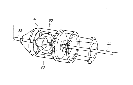
[00028] Referring to Figure 7A, an exploded orthogonal
view of an embodiment of a needle assembly (32) is illustrated
showing a needle cover (46) configured to form a cover or shield
over at least the distal end of the needle (58) when assembled.
A distal needle housing member (48) and proximal needle housing
member (50) assist in maintaining the position of the needle
relative to the syringe body, and in controlling movement of a
latch mechanism that comprises a two-fingered latch member (54)
movably coupled to a movable needle insertion preventing member
(56). The needle member has a sharpened distal end (58)
configured to be inserted in a hypodermic fashion into a tissue
structure of a patient; a proximal end (60) comprises a
proximal tip interface (62) that may be configured to stab into
and couple to a portion of an associated plunger tip, in a
fashion that somewhat mimicks the function of a harpoon
instrument.
[00029] Referring to Figure 7A, an exploded orthogonal
view of an embodiment of a plunger control assembly (44) is
illustrated showing a plunger insertion member (74)
intercoupling a distally-disposed plunger tip coupler member
(64), which may have outer helical threads configured to "screw
into" and couple to the compliant material of an associated
plunger tip as desired, a plunger insertion member proximal
manipulation interface (76), a brake member (68), and a sealing
flange assembly (66) comprising a flange member (72) configured
CA 02916968 2015-12-29
WO 2015/003016 PCT/US2014/045160
to be removably coupled to the proximal flange fitting of a
conventional syringe body (such as that shown in Figure 6 as
element 38) to hold into place a syringe body proximal plug
member (88) with an additional sealing interface comprising an
0-ring (70) to facilitate the buildup of a vacuum load when an
associated plunger tip is inserted relative to the sealing
flange assembly (88). The plunger insertion member proximal
manipulation interface (76) preferably is shaped to allow for
finger and/or thumb manipulation in a manner akin to that
associated with operation of a conventional syringe (i.e.,
depression with a thumb or finger while one or more other
fingers/digits are utilized to apply a counterload at the flange
area). Figure 8 illustrates a partially assembled configuration
wherein a syringe body has been coupled to a plunger control
assembly (44) with the plunger tip coupler member (64) helically
advanced and coupled into the proximal aspect of the compliant
plunger tip (36), and the flange member (72) coupled to the
proximal flanged aspect of the syringe 'body (34). The needle
cover (46) preferably is configured to shield / cover not only
the distal aspect of the needle member (58), but also the
proximal aspect (60, 62), in the depicted configuration, as
shown, to enable an operator to manually grasp the needle
assembly (32) as shown and couple it to the distal aspect of the
syringe body (34) without placing the operator's fingers at risk
for an accidental needle puncturing.
[00030] Referring to Figure 9A, the fairly large overlap
between the the distal end (80) of the syringe body outer
diameter and the interfacing end (78) of the needle cover
provides a relatively large geometric guidance surface for
aligning the needle proximal end (60) as it is guided through
21
CA 02916968 2015-12-29
WO 2015/003016
PCT/US2014/045160
the needle assembly components during assembly/coupling with the
syringe body (34) and guided into fluidic contact with the fluid
reservoir of the syringe body (34).
[00031] Referring
to Figure 9B, a flange member (72) is
shown in relation to an intercoupled syringe body (34) and
plunger insertion member (74). In the depicted embodiment, the
mechanical interface between the plunger insertion member (74)
and the flange member (72) is a brake member or brake assembly
(68) which is configured to be snap-fitted into a recess formed
into the flange member (72). Figure 9C illustrates an opposing
orthogonal view. Figure 9D illustrates a flange member (72)
without the brake member in place to show the recess surface
(86) formed into the flange member (72). Figure 9E shows a
brake member (68) having two outer mounting release tabs (82)
and two inner braking tabs (84). In this embodiment, the brake
member (68) is configured to be snapped into the flange member
recess (86) and held in place by geometric features coupled to
the outer mounting release tabs (82). In such a position, the
two inner braking tabs (84) are geometrically biased toward the
distal end of the syringe body so that they will easily
cantilever away from an inserted (i.e., inserted through the two
inner braking tabs 84) plunger insertion member (element 74 in
other drawings; not shown in Figures 9D and 9E) during such
insertion with relatively low friction - but also resist
retraction of the same plunger insertion member with relatively
high loads until released from the coupling to the flange member
(72). Such a release may be accomplished by depressing the two
outer mounting release tabs (82) - and, indeed, these tabs (82)
are configured to be automatically depressed for such a release
upon full insertion of the plunger insertion member to a final
22
CA 02916968 2015-12-29
WO 2015/003016 PCT/US2014/045160
insertion state wherein the associated plunger tip is interfaced
against the end of the syringe and wherein the plunger insertion
member proximal interface (element 76 in Figure 7B, for example)
is interfaced against the outer mounting release tabs (82) such
that they are released, and the braking member (68) is allowed
to travel along with the plunger insertion member, as shown in
Figure 101, without further resisting retraction of the
associated plunger insertion member.
[00032] Referring to Figure 10A-10K, various operational
aspects of one embodiment of a safety syringe configuration in
accordance with the present invention are illustrated.
Referring to Figure 10A, with a needle assembly coupled to a
syringe body (34), the protective needle cover (46) may be
removed as shown to expose the distal portion of the needle (58)
for injection into a tissue structure of a patient. The
internal support mechanisms of the needle assembly may be
configured to support an injection load of about 5 pounds
without yielding or slipping - to meet a standard such as those
promulgated by organizations such as ISO. In the depicted
embodiment, the proximal end (60) of the needle is configured to
extend into the fluid reservoir (40) of the syringe body to
become a fluid conduit for injection into a tissue structure
that may be temporarily interfaced with a distal portion (58) of
the needle. The needle is threaded through a movable needle
insertion preventing member (56) which imparts only very minimal
frictional loads to the needle in the depicted configuration
wherein the needle is threaded directly through the needle
insertion preventing member (56). Referring to the close-up
view of Figure 10B, with full insertion of the plunger tip to a
final insertion state, the plunger is configured to impart a
23
CA 02916968 2015-12-29
WO 2015/003016 PCT/US2014/045160
compressive load upon the needle and/or a sleeve coupled
thereto, to urge the movable needle insertion preventing member
(56) against the two fingers of the clip or latch member (54),
thereby urging them away from each other (90). The geometry and
structural moduli of these structures may be configured such
that upon full insertion of the plunger tip to a final insertion
state, a geometric step (element 110 as illustrated in Figure
10C) of the movable needle insertion preventing member (56) is
pushed past the two fingers of the latch member (54) so that the
movable needle insertion preventing member (56) is stuck in a
position, by virtue of the ramp surfaces (element 109 as
illustrated in Figure 10C), wherein it will remain biased open -
and also biased to move in a direction (parallel to the axis 96
illustrated in Figure 10D) substantially perpendicular to the
longitudinal axis of the needle (element 98 in Figure 10D, for
example) if freed from the constraint of the needle passing
through it. The movable needle insertion preventing member (56)
may he slidahly interfaced against, and retained by in the axial
direction parallel to the longitudinal axis of the needle (98),
a wall (112) formed in the distal needle housing member (48), as
shown in Figure 10D. With the two fingers of the latch member
(54) biased open, a needle axial position constraining step
(102) formed in the needle and/or a sleeve coupled to the needle
may be freed from the constraint of the latch member (54) and
allowed to retract, as shown in Figure 10D, wherein the two
latch contact points (92, 94) have been pulled apart enough that
the needle is being withdrawn, here by vacuum load built up
within the proximal aspect of the syringe body during insertion
of the plunger tip. Figures 10E and 1OF illustrate sequential
images wherein the movable needle insertion preventing member
(56) has been pushed past the two latch member (54) fingers to
24
CA 02916968 2015-12-29
WO 2015/003016 PCT/US2014/045160
leave them permanently relatively open to that the needle may be
retracted. Referring to Figure 10G, with sufficient retraction
of the needle so that the needle tip (58) is no longer threaded
through a first needle through-aperture (104) and constraining
the motion of the movable needle insertion preventing member
(56), the movable needle insertion preventing member (56) Is
urged by compressive loading of the latch member (54) fingers on
the ramped geometry of the movable needle insertion preventing
member (56) to move along the depicted axis (96) which is
substantially perpendicular to the needle longitudinal axis
(98), thereby placing the needle distal tip (58) in alignment
with the partial-depth needle aperture (106), which is
configured to specifically block and constrain the needle distal
tip (58) as a successive attempt is made to try to insert the
needle. Figures 10H-10J illustrate various aspects of the
plunger control assembly in relation to the syringe body (34).
Referring to Figure 10k, upon full retraction of the needle into
the body of the syringe (34), the needle may he allowed to rest,
or be biased to rest, in a canted or intentionally misaligned
position relative to the syringe body (34) to prevent re-
insertion of the needle relative to the syringe body (34). In
use, the embodiments featured in Figures 10A-10K may function as
follows: an off-the-shelf pre-filled syringe body, such as that
described in reference to Figure 5A, may be coupled to a plunger
control assembly and needle assembly near the Intended use
location; the protective needle cover may be removed, and the
patient injected with the needle, followed by insertion of the
plunger tip to expel the syringe fluid into the patient; as the
plunger tip is seated into the distal end of the syringe body,
several events are intended to occur: a) the proximal end of
the needle is harpooned into the plunger tip to couple these two
CA 02916968 2015-12-29
WO 2015/003016 PCT/US2014/045160
structures; b) a plunger retraction brake is released by
interfacing of the plunger insertion member proximal interface
and brake member outer tabs so that the plunger insertion member
and intercoupled plunger tip and harpooned needle may be
withdrawn relative to the syringe body; c) a vacuum load is
maintained by a substantially sealed proximal volume between the
flange assembly (66) and the plunger tip which is expanded as
the plunger tip is inserted; d) a movable needle retraction-
preventing member (56) urges open the fingers of the associated
latch member (54) to allow the needle to become relatively
unconstrained in terms of proximal retraction or withdrawal
into/toward the syringe body - and upon enough retraction of the
needle (i.e. via the vacuum load pulling the plunger tip, which
is harpoon-coupled to the needle so that the needle is pulled
along proximally into retraction), the movable needle
retraction-preventing member (56) moves over to block further
re-insertion of the needle tip. Thus a single-use safety
syringe configuration is described wherein a single injecting
insertion is made relatively simple, while various mechanisms
interact to allow for a controlled retraction of the needle and
prevention of re-insertion after retraction. During the
injecting insertion, the braking member of the plunger control
assembly allows an operator to remove his hands completely from
the system while the brake retains the position of the plunger
tip relative to the syringe body. The braking member also may
be effective in retaining the geometric relationship between a
plunger tip and an associated syringe body and captured pre-
filled medicine volume during shipping and handling before
utilization. For example, with conventional configurations,
such as that shown in Figure 5A, it is possible that changes in
pressure, such as those created with air transport, may move the
26
CA 02916968 2015-12-29
WO 2015/003016 PCT/US2014/045160
plunger tip relative to the syringe body - possibly past the
acceptable sterile geometric boundaries/barriers. Such relative
motion may be prevented with a locking/braking configuration as
described herein.
[00033] Referring to Figure 11, a process is illustrated
for using an embodiment such as that described in reference to
Figures 10A-10K. After preoperative diagnostics and patient
preparation (200), an safety syringe injection assembly may be
assembled (202). When an injection is desired, the protective
needle cover may be removed (204) and the injection performed
upon a tissue structure of the patient (206, 208). After the
plunger tip has reached a final insertion state, the built up
vacuum load may be utilized to assist in withdrawing the plunger
tip proximally to a retracted state (210); such insertion to
the final insertion state and subsequent retraction of the
needle may cause movement of the movable needle insertion-
preventing member to move into a configuration wherein it will
prevent re-insertion of the needle (212); insertion of the
plunger tip to the final insertion state also causes the plunger
braking member to mechanically transition to an un-braked state
wherein plunger retraction is not mechanically resisted by the
brake (214). The retracted needle may be fully retracted into
the syringe body and positioned in a canted configuration to
prevent further insertion (216).
[00034] Referring to Figures 12A-12G, another embodiment
is depicted wherein a mechanism is configured to allow for a
full injection insertion, after which the needle may he
automatically withdrawn, and in certain embodiments, also
prevented from re-insertion. For simplicity of illustration,
braking features, such as those described in reference to
27
CA 02916968 2015-12-29
WO 2015/003016 PCT/US2014/045160
Figures 9A-10K, are not shown in the embodiments of Figures 12A-
12G, but they may be present in certain variations and
configurations, and are described, for example, in the
embodiment of Figure 13.
[00035] Referring to Figures 12A-12G, a safety syringe
assembly is depicted wherein a needle housing (120) may be
coupled to a conventional syringe body (34) and utilized to
facilitate a single full insertion of the needle, after which
needle withdrawal may be automatically facilitated by a
combination of a withdrawal-prevention mechanism converting to a
state wherein needle withdrawal is freely allowed, and a vacuum
load developed in the captured volume proximal to the plunger
tip in the syringe body being allowed to facilitate needle
withdrawal, as described above. As shown in Figure 12A, a
plunger tip (36) is shown ready to inject the contents of the
syringe body (34) into the needle, the distal portion (58) of
which may be directly interfaced with a patient tissue
structure. Referring to Figure 12B, a close-up view of which is
shown in Figure 12D, with the plunger tip (36) almost fully
inserted, the needle remains locked in place and prevented from
withdrawal by a locking configuration comprising an 0-ring
forcibly urged against a needle sleeve (126) coupled to the
needle. The proximal needle end (60) features a harpoon-like
interface (64) configured to stab into the plunger tip (36)
material and couple thereto. The depicted embodiment also
features a polymeric backing (122) of the plunger tip (36)
selected to create a more robust coupling of the needle and
plunger tip. Referring to Figure 120, a close-up view of which
is shown in Figure 12E, with complete insertion of the plunger
tip (36), the needle sleeve (126) urges a load-transferring
28
CA 02916968 2015-12-29
WO 2015/003016 PCT/US2014/045160
member (128) at least partway through a plurality of latch
members (130, 131), which rotate (132) as shown in Figure 12E,
to release an 0-ring loading member (134) from its prior
constraint up against the 0-ring (170), allowing the 0-ring to
slightly relax and thereby free the needle of the previous axial
withdrawal constraint, after which retraction of the plunger
insertion member (74), such as by vacuum load or manually, will
pull the needle into proximal withdrawal relative to the syringe
body (34), as shown in Figures 12F and 12G.
[00036] Referring to Figure 13, an embodiment similar to
that of Figure 11 is illustrated, with the exception that in the
embodiment of Figure 13, after the injection insertion (208),
insertion to a final insertion state releases compression of an
0-ring from against the needle, thereby allowing the needle to
be withdrawn (218), as described above in reference to Figures
12A-12G.
[00037] Referring to Figures 14A-14G, an embodiment
similar to that of Figures 12A-12G is illustrated, with the
exception that the embodiment of Figures 14A-14G features an
off-axis or bent proximal harpooning or barb interface (136)
that is configured to cause a fully-withdrawn needle to be
canted to the side, or out of alignment relative to the syringe
body (34), so that the needle cannot be re-inserted by another
attempted insertion of the plunger tip. Figure 15, which is
similar to Figure 13, features the addition of such misalignment
of the needle member upon full withdrawal of the needle member
into the syringe body (220) to prevent re-insertion of the
needle member relative to the syringe body (i.e., to prevent re-
use, or accidental/undesired contact of a needle tip with a
person or object).
29
CA 02916968 2015-12-29
WO 2015/003016 PCT/US2014/045160
[00038] Referring to Figures 16A-16H, an embodiment
similar to that of Figures 12A-12G is illustrated, with the
exception that the embodiment of Figures 16A-16H features double
off-axis or bent proximal harpooning or barb interface (138)
that is configured to cause a fully-withdrawn needle to be
canted to the side, or out of alignment relative to the syringe
body (34), so that the needle cannot be re-inserted by another
attempted insertion of the plunger tip - and also to provide an
even more robust harpoon-style coupling between the proximal
portion of the needle (60) and the plunger tip (36). Figure 17,
which is similar to Figure 13, features the addition of such
misalignment of the needle member upon full withdrawal of the
needle member into the syringe body using the twin coupling
member (222) to prevent re-insertion of the needle member
relative to the syringe body (i.e., to prevent re-use, or
accidental/undesired contact of a needle tip with a person or
object).
[00039] Referring to Figures 18A-181, an embodiment
similar to that of Figures 12A-12G is illustrated, with the
exception that the embodiment of Figures 18A-18I features a
quite different mechanism for allowing insertion of the needle
and resisting retraction until full insertion of the needle,
after which retraction of the needle is facilitated by
deformation of a clip member (140). For example, referring to
the close-up views of Figures 18D and 18E, in Figure 18D, a
close-up view of the configuration of Figure 1871, the clip
member (140), with two through-apertures (142, 144) that are
slightly out of alignment, prevents movement of the needle (58)
relative to the syringe body (34). Figure 18E shows the plunger
tip almost fully, but not fully, inserted relative to the
CA 02916968 2015-12-29
WO 2015/003016 PCT/US2014/045160
syringe body, as in Figure 18B. Upon full insertion of the
plunger tip (36), as in Figures 18C and 18F, a needle sleeve
member, or a step formed in the outer geometry of the needle,
compresses the clip member (140), causing the apertures (142,
144) to become more aligned, if not completely aligned, after
which they may be held in such configuration by a feature (148)
formed into the needle housing (120) configured to retain such
configuration so that the needle may be withdrawn, such as by a
manually applied load or vacuum load, as described above. In
other words, the clip member (140) may be squeezed by virtue of
a physical coupling through the needle assembly to the plunger
tip (36), causing deformation (which may be configured to be
plastic deformation or elastic deformation, depending upon the
materials and dimensions selected for the clip; in an elastic
deformation configuration, the holding feature 148 assists more
prominently in retaining the deformed shape of the clip) of the
clip (140) to a shape such as that shown in Figure 18F, wherein
the needle (58) is allowed to retract without substantial
resistance from the clip, due to alignment of the apertures of
the clip. Figure 18H shows an incomplete withdrawal of the
needle into the syringe body; Figure 181 shows a complete
withdrawal of the needle into the syringe body, with canting of
the withdrawn needle to the side to prevent further insertion of
the needle relative to the syringe body, as described above.
The embodiment of Figure 19 is similar to that of Figure 15,
with the exception that the embodiment of Figure 19 features
deformation of a needle retraction resistance clip, thereby
allowing the needle to be withdrawn (224).
[00040] Referring to Figures 20A-20I, an embodiment
similar to that of Figures 12A-12G is illustrated, with the
31
CA 02916968 2015-12-29
WO 2015/003016 PCT/US2014/045160
exception that the embodiment of Figures 20A-201 features a
quite different mechanism for resisting needle retraction until
full insertion of the needle, after which retraction of the
needle is facilitated by movement of a cantilevered latch member
(152) of a latch assembly (150) coupled to the distal needle
housing (120). For example, referring to the close-up views of
Figures 20D and 20E, in Figure 20D, a close-up view of the
configuration of Figure 20A, the latch member (152) prevents
withdrawal of the of the needle (58) relative to the syringe
body (34) by interfacing with a recess (154) formed into the
needle or a sleeve member coupled thereto. Figure 20E shows the
plunger tip almost fully, but not fully, inserted relative to
the syringe body, as in Figure 20B. Upon full insertion of the
plunger tip (36), as in Figures 20C and 20F, the needle and/or
needle sleeve (156) member is advanced slightly forward,
dislodging the latch member (152) from the recess (154), after
which the needle may be withdrawn (such as is shown in Figure
20n), such as by a manually applied load or vacuum load, as
described above. Figure 20H shows an incomplete withdrawal of
the needle into the syringe body; Figure 201 shows a complete
withdrawal of the needle into the syringe body, with canting of
the withdrawn needle to the side to prevent further insertion of
the needle relative to the syringe body, as described above.
The embodiment of Figure 21 is similar to that of Figure 19,
with the exception that the embodiment of Figure 21 features
mechanical reconfiguration of a needle retraction resistance
latch, thereby allowing the needle to be withdrawn (226).
[00041] Referring to Figures 22A-22K, an embodiment is
depicted wherein a needle assembly features a proximally
disposed intercoupling member (160) configured to be coupled
32
CA 02916968 2015-12-29
WO 2015/003016 PCT/US2014/045160
(via relative rotation) to a distal Luer fitting (14) of a
conventional syringe assembly, and also configured to be coupled
(also via relative rotation - preferably the same rotational
direction as the first rotation) to an inner surface of the
needle housing (166) in a manner wherein the proximal aspect
(60, 64) of the needle remain shielded from the hands of an
operator, or from other objects. Referring to Figure 22A, the
needle assembly comprises a needle coupled through a needle
housing (166) and intercoupled intercoupling member (160) so
that the proximal end of the needle (60, 64) does not extend
beyond the proximal end of the intercoupling member (160). A
removable needle shield (158) isolates the distal portion (58)
of the needle and is removable at injection time; further, the
removable needle shield (158) features rotational manipulation
features, such as small wing features, to facilitate easy
rotation of the needle assembly relative to the syringe body
(34) to which it is to be coupled. Such features may be
particularly useful for the home healthcare market wherein
patients suffering from maladies such as arthritis may desire to
use syringes for injection and have difficulty without physical
feature aids. Referring to Figure 22B, the syringe assembly and
needle assembly are placed into contact with the Luer interface
of the intercoupling member (160) positioned against the Luer
interface of the syringe assembly. With twisting engagement,
the intercoupling begins via the intercoupling member (160), as
shown in the cross sectional view of Figure 22C. With further
twisting, the proximal coupling interface (164) of the
intercoupling member (160) causes closer engagement of the
intercoupling member (160) using the inner helical thread
interface (168) of the needle housing - until the coupling is
complete, as shown in Figures 22D and 22E. Subsequently the
33
CA 02916968 2015-12-29
WO 2015/003016 PCT/US2014/045160
removable needle shield (158) may be removed and an injection of
fluid started, as shown in Figures 22F and 22G. Upon full
insertion of the plunger tip (36) relative to the syringe body
(34), the proximal needle harpooning interface (64) may be
coupled to the plunger tip (36), and an un-latching
configuration similar to that shown in reference to Figures 20A-
201 may allow for proximal withdrawal of the needle, as shown in
Figures 22I-22K.
[00042] Referring to Figure 23, a configuration similar
to that depicted in Figure 12A is illustrated, with exception
that the configuration of Figure 23 features an integrated
spring member (51) intercoupled between the needle member (58)
and the distal end of the syringe body (34) to provide a needle
retraction load sufficient to retract the needle, as described
above - but in the context of a vacuum retraction load.
[00043] Referring to Figure 24, a configuration similar
to that depicted in Figure 12A is illustrated, with exception
that the configuration of Figure 23 features an integrated
spring member (101) intercoupled between the proximal end (38)
of the syringe body (34) and the proximal end of the plunger
insertion member (74) to provide a needle retraction load
sufficient to retract the needle, as described above - but in
the context of a vacuum retraction load.
[00044] Figures 23 and 24 illustrate that loads other
than vacuum loads may be utilized to assist in retracting a
needle member with various safety configurations described
herein. Indeed, in simplified configurations, which may be
desirable from cost and other perspectives, needle re-insertion
prevention may be accomplished using needle assemblies such as
those described herein, with only manual retraction of the
34
CA 02916968 2015-12-29
W02015/003016 PCT/US2014/045160
needle member (i.e., while various self-retracting-after-full-
insertion configurations are described herein, manual retraction
configurations also may benefit from the safety provided by the
needle assemblies described herein wherein re-insertion of a
needle after a first full insertion is physically prevented).
[00045] Referring back to Figures 11, 13, 15, 19, and 21,
the syringe body (preloaded with medicine), needle assembly, and
plunger control assembly are illustrated (202) as being part of
an in-situ process (i.e., adjacent the point of use - such as in
a hospital or home healthcare scenario, and after preoperative
diagnostics and patient preparation 200). In other embodiments,
a plunger control assembly such as that illustrated in Figures 6
and 7B (44) may arrive at the intervention site pre-assembled
with a syringe body (i.e., such an assembly would be pre-
assembled before delivery to the intervention site); further,
in other embodiments, a needle assembly such as that illustrated
in Figures 6 and 7A (32) may arrive at the intervention site
pre-assembled with a syringe body (i.e., such an assembly would
be pre-assembled before delivery to the intervention site);
indeed, in other embodiments, both a needle assembly (32) and
plunger control assembly (44) may be pre-assembled with a
syringe body at the preparation factory or other location before
delivery to the intervention site.
[00046] Suitable polymeric materials for the various
components of these embodiments include but are not limited to
acetal, polycarbonate, poly vinyl chloride, polypropylene,
polystyrene, ABS, nylon, glass-filled nylon, glass-filled
acetal, peek, glass-filled peek, carbon-fiber-filled peek, COC
(cyclic olefin copolymer), COP (cyclic olefin polymer), PEI
CA 02916968 2015-12-29
WO 2015/003016 PCT/US2014/045160
(Ultem), glass-filled PEI, and pekk, as well as copolymers
thereof.
[00047] Suitable structural metals for structures such as
the plunger insertion member include but are not limited to
stainless steel, steel with chrome coating, brass, nickel, and
titanium, as well as alloys thereof.
[00048] Suitable needle member sizes range from about 34
gauge / 6 millimeters long - to about 20 gauge / 2.5 inches
long.
[00049] Various exemplary embodiments of the invention
are described herein. Reference is made to these examples in a
non-limiting sense. They are provided to illustrate more broadly
applicable aspects of the invention. Various changes may be made
to the invention described and equivalents may be substituted
without departing from the true spirit and scope of the
invention. In addition, many modifications may be made to adapt
a particular situation, material, composition of matter,
process, process act(s) or step(s) to the objective(s), spirit
or scope of the present invention. Further, as will be
appreciated by those with skill in the art that each of the
individual variations described and illustrated herein has
discrete components and features which may be readily separated
from or combined with the features of any of the other several
embodiments without departing from the scope or spirit of the
present inventions. All such modifications are intended to be
within the scope of claims associated with this disclosure.
[00050] Any of the devices described for carrying out the
subject diagnostic or interventional procedures may be provided
in packaged combination for use in executing such interventions.
These supply "kits" may further include instructions for use and
36
CA 02916968 2015-12-29
WO 2015/003016 PCT/US2014/045160
be packaged in sterile trays or containers as commonly employed
for such purposes.
[00051] The invention includes methods that may be
performed using the subject devices. The methods may comprise
the act of providing such a suitable device. Such provision may
be performed by the end user. In other words, the "providing"
act merely requires the end user obtain, access, approach,
position, set-up, activate, power-up or otherwise act to provide
the requisite device in the subject method. Methods recited
herein may be carried out in any order of the recited events
which is logically possible, as well as in the recited order of
events.
[00052] Exemplary aspects of the invention, together with
details regarding material selection and manufacture have been
set forth above. As for other details of the present invention,
these may be appreciated in connection with the above-referenced
patents and publications as well as generally known or
appreciated by those with skill in the art. For example, one
with skill in the art will appreciate that one or more
lubricious coatings (e.g., hydrophilic polymers such as
polyvinylpyrrolidone-based compositions, fluoropolymers such as
tetrafluoroethylene, hydrophilic gel or silicones) may be used
in connection with various portions of the devices, such as
relatively large interfacial surfaces of movably coupled parts,
if desired, for example, to facilitate low friction manipulation
or advancement of such objects relative to other portions of the
instrumentation or nearby tissue structures. The same may hold
true with respect to method-based aspects of the invention in
terms of additional acts as commonly or logically employed.
37
CA 02916968 2016-03-09
[00053] In addition, though the invention has been
described in reference to several examples optionally
incorporating various features, the invention is not to
be limited to that which is described or indicated as
contemplated with respect to each variation of the
invention. Various changes may be made to the invention
described and equivalents (whether recited herein or not
included for the sake of some brevity) may be substituted
without departing from the scope of the invention. In
addition, where a range of values is provided, it is
understood that every intervening value, between the
upper and lower limit of that range and any other stated
or intervening value in that stated range, is encompassed
within the invention.
[00054] Also, it is contemplated that any optional
feature of the inventive variations described may be set
forth and claimed independently, or in combination with any
one or more of the features described herein. Reference to
a singular item, includes the possibility that there are
plural of the same items present. More specifically, as
used herein and in claims associated hereto, the singular
forms "a," "an," "said," and "the" include plural referents
unless the specifically stated otherwise. In other words,
use of the articles allow for "at least one" of the subject
item in the description above as well as claims associated
with this disclosure. It is further noted that such claims
may be drafted to exclude any optional element. As such,
this statement is intended to serve as antecedent basis for
use of such exclusive terminology as "solely," "only" and
the like in connection with the recitation of claim
elements, or use of a "negative" limitation.
38
CA 02916968 2015-12-29
WO 2015/003016 PCT/US2014/045160
[00055] Without the use of such exclusive terminology,
the term "comprising" in claims associated with this disclosure
shall allow for the inclusion of any additional element--
irrespective of whether a given number of elements are
enumerated in such claims, or the addition of a feature could be
regarded as transforming the nature of an element set forth in
such claims. Except as specifically defined herein, all
technical and scientific terms used herein are to be given as
broad a commonly understood meaning as possible while
maintaining claim validity.
[00056] The breadth of the present invention is not to be
limited to the examples provided and/or the subject
specification, but rather only by the scope of claim language
associated with this disclosure.
39