Note: Descriptions are shown in the official language in which they were submitted.
CA 02916987 2015-12-24
1
WO 2014/209211 PCT/SE2014/050785
ARRANGEMENT AND METHOD FOR POSITIONING CARTRIDGES FORA ROCK
GROUTING EQUIPMENT
TECHNICAL FIELD
The present invention relates to an arrangement and a method for a rock
grouting
equipment for positioning of at least one cartridge.
BACKGROUND
For rock reinforcement often two-component resin with hardener is used to fix
rock
bolts introduced as reinforcement in bored holes in the rock. The resin is
supplied in the
form of cartridges where the non-hardened resin is enclosed in an outer cover
and where
hardener in turn is enclosed in a separate part inside the cover. After a
suitable number of
resin cartridges have been introduced in a borehole a rock bolt is introduced
during
rotation whereby the cover of the cartridges is teared apart and the non-
hardened resin is
mixed with the hardener. The rotation of the rock bolt is proceeded until the
two-
component resin starts harden. The rock bolt will thereby be fixed in its
position in the
bore hole.
Earlier known arrangements to load a borehole with this type of cartridges
often
comprises a grouting nozzle with a tube which is brought to abut the borehole
to be
loaded with cartridges. From this tube a flexible hose leads to a loading tube
placed
adjacent to a rock drilling equipment. One or several cartridges is placed in
loading
position in the loading arrangement. Thereafter a pressure medium is supplied
to the
loading tube and the one, or several, in loading position placed cartridge is
fired by the
pressure medium through the flexible hose via the grouting nozzle and into the
borehole
to be loaded. The cartridges are placed manually in firing position in the
loading
arrangement.
Manual handling of this type of cartridges shall as far as possible be avoided
since
the two-component resin is very insanitary. Several proposed solutions for
automatically
feed and fire this type of cartridges have been proposed. This type of
cartridges is
however difficult to handle since their outer cover is relatively soft and
they thereby have a
kind of formless shape. Another problem with the soft cover is that the
cartridges relatively
easy may tear apart. A comprehensive cleaning of the feeding means from
spilled both
non-hardened and hardened resin is then necessary which generally causes a
longer stop
RECORD COPY TRANSLATION
(Rule 12.4)
CA 02916987 2015-12-24
2
WO 2014/209211 PCT/SE2014/050785
in operation. Further, variations in the size of the cartridges may occur
which further
causes problem. The surface of the cartridges is also of such nature that they
may easy
adhere to each other which also causes problem when automatically feeding.
US 639 01 89 is an example of automatically feeding means for cartridges
intended to be used with a rock drilling equipment. The known arrangement
comprises a
rotatable cartridge storehouse provided with a plurality of loading tubes
arranged along
with the periphery of the storehouse. The cartridge storehouse may be loaded
in advance
with a large number of cartridges. The storehouse is thereafter rotated
stepwise whereby
one in a loading tube placed cartridge is brought into firing position. By
applying
compressed air to the loading tubes, the cartridge is fired away from the
loading tube via a
connecting hose positioned in the firing direction and further into a bore
hole.
The known arrangement however shows a plurality of disadvantages. Many
separate loading tubes makes the design large, heavy and clumsy, and expensive
and
complicated to manufacture. Further, it does not manage to handle cartridges
of different
dimensions. If a cartridge tears apart, the storehouse with its complex design
is difficult to
clean with long down time following. The design further causes that the
cartridges must be
handled one by one when loading the storehouse.
Another example of automatically feeding means is shown in US 2008/0145152.
The known arrangement comprises one or several containers comprising
cartridges
arranged horizontally laying on each other, and placed above a loading area
being in
connection with a firing area for the cartridges. Between each container and
the loading
area is a rotating distributor arranged to move the cartridges one by one.
The V-shaped designed containers which uses gravity for feeding causes that a
cartridge is exposed to large weight from above laying cartridges when the
storehouse is
loaded with many cartridges. During feeding the cartridge is at the same time
exposed to
friction against the sides of the design and to the above and below placed
cartridges. This
causes a risk that some of the cartridges tears apart with subsequent down
time. The
design is complex with both fixed and movable parts which makes it difficult
to clean.
A further known arrangement is shown in WO 99/64722. Also in this design
cartridges is fed with help from gravity. The cartridges that is located far
down are thus
also in this feeding means exposed to large weight from above placed
cartridges and to
friction against the sides of the design and from above and below placed
cartridges. The
design is complex and comprises movable parts which makes it complicated to
manufacture and difficult to clean.
81793125
3
SUMMARY
A purpose is to provide an arrangement that at least in part may solve the
problems mentioned above. This purpose may be according to one aspect obtained
by an arrangement for a rock grouting equipment for positioning at least one
cartridge. The arrangement comprises at least one storehouse arranged around
an
axis and intended to comprise a plurality of said cartridges. The storehouse
comprises at least one tray, in which tray a plurality of cartridges are
placed. Thus a
stack of cartridges may be placed in said at least one tray, and these
cartridges may
move freely in the tray since they are not placed in separate loading tubes.
The
arrangement further comprises at least one in relation to the axis in radial
direction
extending catching organ. The catching organ is arranged to perform a rotating
movement around the axis. The catching organ is arranged to, during said
rotating
movement, catch at least one of said cartridges.
According to another aspect a method in such arrangement is provided. The
method comprises rotating said catching organ around the axis and catching at
least
one of said cartridges during said rotating movement.
According to another aspect, there is provided an arrangement for a rock
grouting equipment for positioning at least one cartridge, wherein the
arrangement
comprises: at least one magazine arranged around a substantially horizontally
arranged axis for holding a plurality of said cartridges, said magazine
comprising at
least one compartment, wherein said at least one compartment is adapted to
receive
the plurality of said cartridges placed therein, at least one catching member
extending
in a radial direction relative to the horizontally arranged axis, wherein said
catching
member is arranged to perform a rotating movement around the axis, and wherein
said catching member is arranged and formed such that, during said rotating
movement, at least one of said cartridges is caught between the catching
member
and an inner surface of the magazine body.
According to another aspect, there is provided a method in an arrangement for
Date Recue/Date Received 2020-08-27
81793125
3a
a rock grouting equipment, wherein said arrangement comprises at least one
magazine arranged around a substantially horizontally arranged axis for
holding a
plurality of cartridges, said magazine comprising at least one compartment,
wherein
said at least one compartment is adapted to receive a plurality of said
cartridges
placed therein, and at least one catching member extending in a radial
direction
relative to the horizontally arranged axis, wherein the method comprises
rotating said
catching member around the substantially horizontally arranged axis, catching
at
least one of said cartridges during said rotating movement by the at least one
catching member between the catching member and an inner surface of the
magazine body.
BRIEF DESCRIPTION OF FIGURES
Figure 1 is a view of one embodiment of the arrangement.
Figure 2 is a view of an alternative embodiment of the arrangement.
Figure 3 shows a further embodiment of the arrangement seen from the front.
Figure 4 is a perspective view of an embodiment of the arrangement.
Figure 5 is an exploded view of an embodiment of the arrangement.
Figure 6 is a flow chart showing an exemplified method.
DETAILED DESCRIPTION
Exemplified embodiments will now be described more in detail with reference to
the attached figures. The same number in the figures refers throughout to the
same
element. Note that the figures not necessary are made to scale and that some
details
may have been exaggerated for clarity reasons.
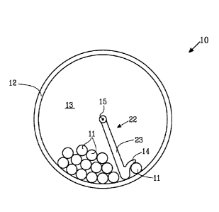
Figure 1 shows an embodiment of an arrangement 10 for a rock grouting
equipment for positioning of at least one cartridge. The arrangement comprises
a
Date Recue/Date Received 2020-08-27
CA 02916987 2015-12-24
4
WO 2014/209211 PCT/SE2014/050785
storehouse 12 arranged around an axis 15 and intended to comprise a plurality
of
cartridges 11. The storehouse 12 is shown in the figure with a substantially
cylindrical
form but may as well have some other around the axis 15 arranged arbitrary
form for
example with hexagonal or polygonal cross section. The storehouse 12 comprises
at least
one tray 13 where a plurality of cartridges 11 is placed. The arrangement 10
comprises
also at least one in relation to the axis 15 in radial direction extending
catching organ, in
the example shown in the figure formed like longitudinal ridges 3 formed in
the inner
surface of the storehouse. Respective ridge 3 may extend along the whole
length of the
storehouse 12, or along a part of the length of the storehouse, or be divided
in several
separate parts.
The catching organ comprises thus one or several in parallel with the axis
extending ridges 3 arranged in the inner surface area 4 of the storehouse. The
ridges 3
are arranged to perform a rotating movement around the axis 15 by that the
storehouse
12 is brought into a rotating movement around the axis 15. The in the
storehouse 12
placed cartridges 11 will then slip along the inner surface area 4 of the
storehouse and the
catching the means. The ridges 3 are arranged to, during said rotating
movement, catch
at least one of said cartridges 11. If a flowing medium, like water, is added
to the
storehouse 12 in order to decrease the friction between the cartridges 11 and
between the
cartridges 11 and the inner surface area 4 of the storehouse, the flow is
facilitated if the
ridge is divided in several parts.
Figure 2 shows another embodiment of an arrangement 10 for feeding cartridges
11 seen from the front. The arrangement comprises a storehouse 12 intended to
comprise
a plurality of cartridges 11. The storehouse 12 comprises a tray 13, in which
tray a
plurality of cartridges is placed. A rotor 22 provided with one in relation to
the axis 15
radially extending rotor blade 23 is arranged to be placed inside the
storehouse 12.
Further, catching organ is comprised in form of that the rotor blade 23 has
been provided
with convey means 14. The rotor blade 23 is arranged to perform, around an
axis 15, one
in relation to the storehouse 12 rotating movement. The axis 15 may have any
direction.
In the example shown in the figure a substantially horizontally arranged axis
15 is shown.
When the rotor blade 23 is brought into rotating movement around the axis 15
the
cartridges 11 will slip on the inner surface area 4 of the storehouse 12. The
convey means
14 will then, during said rotating movement, catch at least one of the
cartridges 11. The
catching organ, in the figure shown as convey means 14, is arranged to place
at least one
cartridge 11 in a predetermined position, for example but not necessary at the
periphery
CA 02916987 2015-12-24
WO 2014/209211 PCT/SE2014/050785
of the storehouse. The rotor blade 23 may be brought to stay in a specific
position, and is
preferably fixed in said specific position. From the predetermined position
may the
cartridge, or the cartridges, be moved to a loading position for firing, for
example with help
from a linear actuator that pushes the cartridge, or the cartridges, in a
direction in parallel
5 with the axis 15 in a firing arrangement, i.e. a firing hose (not shown in
figure).
Alternatively, the cartridge or the cartridges may be fired directly from said
specific
position.
Figure 3 shows a further embodiment of an arrangement 10 for feeding of
cartridges 11 seen from the front. The arrangement comprises a storehouse 12
intended
to comprise a plurality of cartridges 11 in several separated trays 13. A
rotor 22 with
several rotor blades 23 is arranged in the storehouse 12, wherein the rotor
blades 23 form
delimitations for the trays 13 where the cartridges 11 are placed. In
respective tray 13 a
plurality of cartridges 11 is placed. The rotor 22 is arranged to perform a
rotating
movement around the axis 15. When the rotor 22 is brought into rotating
movement
around the axis 15 the cartridges 11 in the trays 13 will slip on the inner
surface area 4 of
the storehouse 12. The rotor blades 23 are provided with convey means 14 that
will,
during said rotating movement, catch at least one of the cartridges 11. The
convey means
14 is arranged to place the cartridge, or the cartridges, 11 in a
predetermined position.
The rotating movement of the rotor 22 may be stopped and the rotor may be
fixed and
locked in at least one certain position. From the predetermined position may
the cartridge,
or the cartridges 11, be moved to a loading position for firing, or be fired
directly.
Figure 4 is a perspective view of an embodiment of an arrangement 10 for
feeding
resin cartridges. A plurality of convey means 14 is arranged in the periphery
part of the
rotor blades 23. The position of the convey means 14 in radial direction may
be adjusted.
Since the exact position of the convey means 14 may be adjusted individually,
the
horizontal position of the one or several caught cartridges may be tuned. In
the figure is
also an occlusive cover 43 shown. To decrease the friction between the
individual
cartridges 11 and between the cartridges 11 and the inner surface area of the
storehouse
12, the storehouse 12 may in part be filled with some friction reducing
medium. This
medium may be any that decreases the friction, for example may water or water
mixed
with soap be used.
CA 02916987 2015-12-24
6
WO 2014/209211 PCT/SE2014/050785
Figure 5 is a detailed exploded view of an exemplified embodiment of an
arrangement 10 for a rock grouting equipment intended for automatically
feeding and
positioning a large number of cartridges 11, for example 50-100 cartridges.
The
arrangement comprises at least one substantially cylindrically shaped
storehouse 12
intended to comprise a plurality of cartridges 11. The storehouse is arranged
rotatable
symmetrical around one substantially horizontal axis 15 and is at least in
part enclosed by
a frame 41.
A rotor 22 is arranged to be placed inside the storehouse 12. From the central
axis
of the rotor one or several rotor blade 23 extends. In the example shown in
the figure the
rotor 22 is provided with four rotor blades 23. When the rotor 22 is placed
inside the
storehouse 12 the rotor blades 23 forms in radial direction extending
delimitations
whereby four of the by the rotor blades 23 separated trays 13 for placing of
cartridges 11
is formed. The rotor 22 is arranged to perform, around the substantially
horizontally
arranged axis 15, one in relation to the storehouse 12 rotating movement. The
rotor 22 is
driven by a driving engine 47 which transfers torque to the rotor 22 via a
drive shaft 50
and a driving arrangement 51. At the periphery edge of the rotor blade 23 is
one or
several convey means 14 arranged. In the example shown in the figure the rotor
blades
23 are provided with three convey means 14.
The convey means 14 is arranged to, during said rotating movement, catch one
or
several of the cartridges 11. When the rotor 22 is rotated the in the trays 13
placed
cartridges 11 will slip on the surface area of the storehouse 12. The inner
surface area of
the storehouse 12 is provided with a surface which provides a smooth surface
with low
friction against which surface the in the storehouse 12 placed cartridges 11
may easy slip.
The smooth surface may for example be a polyurethane surface. The arrangement
10
may be provided with an occlusive lock 43. To further decrease the friction
between the
cartridges 11 and the inner surface area of the storehouse 12 may the
storehouse 12 in
part be filled with some friction decreasing medium, for example water.
This also decreases the friction between the cartridges 11 placed in the
storehouse and the risk that the cartridges adhere to each other or to the
inner surface of
the storehouse decreases. Thus, the risk that some cartridge tears apart
decreases.
During the rotating movement the against the surface area of the storehouse
slipping
cartridges will be caught by the convey means 14. The rotating movement of the
rotor 22
proceeds until one in advance specific position where the position of the
rotor 22 may be
fixed with a locking arm 49. The arrangement further comprises an indexing
disc 48.
CA 02916987 2015-12-24
7
WO 2014/209211 PCT/SE2014/050785
The convey means 14 is arranged in the periphery part of the rotor blades 23.
The
position of the convey means 14 in radial direction may be adjusted. Since the
exact
position of the convey means 14 may be adjusted individually, the horizontal
position of
the one or several caught cartridges may be tuned. The arrangement 10 is
provided with
a connection 46 to one or several firing arrangements like one or several
firing hoses (not
shown in figure). The arrangement 10 further comprises an actuator 42 arranged
to move
the cartridge, or the cartridges, 11 from the predetermined position to an
adjacent to the
storehouse 12 arranged firing arrangement like a firing hose (not shown ). The
actuator 42
is arranged to act linear in a direction substantially in parallel with the
axis 15.
When the cartridge, or the cartridges, 11 is positioned they are moved with
help
from the actuator 42 from the storehouse 12 to the firing hose. The linear
actuator 42 is
arranged to act in a direction along with the axis 14 and to slip in a cut
groove 5 in the
storehouse 12 with help from a driving mechanism 6. The actuator 42 will thus
push the
one or several positioned cartridges 11 out from the storehouse 12 and into
the firing
hose. In this way one or several cartridges 11 may be placed in the firing
hose. A sensor
44 may indicate that one or several cartridges have been placed in the firing
hose. The
sensor 44 may be any sensing sensor, for example a photocell, or a sensor that
senses
weight. The rotating movement and the steps above are repeated until a desired
number
of cartridges 11 are placed in the firing hose. The actuator 42 is arranged to
seal the
opening of the firing hose turned towards the storehouse 12. For this purpose
the actuator
42 may for example have a circular cross section and may be provided with a
conical
tapered form, or with a sealing membrane. When the end of the firing hose is
sealed gas,
for example compressed air, is applied to the firing hose via a connection 45
whereby the
cartridges 11 are fired.
Figure 6 is a flow chart showing an exemplified method. The method is
performed
in an arrangement 10 for a rock grouting equipment as described according to
any of the
examples above. The method comprises rotating 101 catching organ 3, 14 around
an axis
15. At least one cartridge 11 is caught 102 by the catching organ 3, 14 during
the rotating
movement. The method further comprises positioning 103 at least one caught
cartridge 11
in a predetermined position. The catching organ 3, 14 may comprise one or
several
convey means 14 which position in radial direction may be adjusted. The
positioning 103
of the one or several caught cartridges 11 may be adjusted by adjusting the
position in
radial direction of the one or several convey means. The method may further
comprise
moving 104 the cartridge, or the cartridges, 11 from the predetermined
position to one, or
CA 02916987 2015-12-24
21069-213
8
several, adjacent to the storehouse 12 arranged firing hoses. Moving 104 may
occur
linear in a direction substantially in parallel with the axis 15. The method
may further
comprise indicating 105 presence of one or several cartridges 11 in said
firing hose by a
sensor 44.
The above exemplified arrangements and the methods show a plurality of
advantages. According to some aspects, the robust design may enable a compact
and
light weight arrangement. The design shows few parts which partially may be
taken apart
which may facilitate cleaning. Refill of cartridges may be simple and the
arrangement has
capacity to handle many cartridges. Further, cartridges with the same
hardening time or
the same dimensions may be placed in different trays if desired. According to
some
aspects, the arrangement may not require the same advanced control equipment
like
earlier known designs.
The skilled person within the field realizes that embodiments described above
may be combined. Thus, the invention is not limited to the described
embodiments. The
invention is limited only by the patent claims defining the scope of
protection.