Note: Descriptions are shown in the official language in which they were submitted.
CA 02917059 2015-12-30
WO 2015/003208 PCT/AU2014/000700
- 1 -
STRESS DISTRIBUTION ELEMENT FOR A GRINDING MILL SHELL
Field of the Invention
[0001] The present invention relates to a stress distribution element for a
mill shell
and in a particular a stress distribution element for use in a mill. The
invention has
been developed primarily for use as stress distribution element for joints in
grinding mill
shells and will be described hereinafter by reference to this application.
However, it will
be appreciated that the invention is not limited to this particular field of
use, but also
extends to other types of structures that require attenuation of stresses
along joints and
seams.
Background of the Invention
[0002] The following discussion of the prior art is intended to present the
invention in
an appropriate technical context and allow its advantages to be properly
appreciated.
Unless clearly indicated to the contrary, however, reference to any prior art
in this
specification should not be construed as an express or implied admission that
such art
is widely known or forms part of common general knowledge in the field.
[0003] A grinding mill has a generally cylindrical mill chamber called a
mill body or
"shell" and two journal shafts, the journals being mounted upon supports for
rotation.
Large scale ball mills, typically more than 24' in diameter and 40' in length,
are
generally constructed by dividing the mill shell into individual components
called "shell
sections", whereby the shell sections have "joints" between adjoining sections
for
facilitating later assembly on-site. The division of the mill shell into
modular shell
sections assists in the manufacture and transportation of the mill to the
plant site.
Depending on the size of the mill shell, there may be numerous splits in the
lengthwise
direction, each lengthwise split differentiating one shell "can" from the next
shell "can".
Each shell can comprise one-half, one-third or one quarter of the mill shell
diameter.
Each shell section has at least one connecting element in the form of a flange
that
extends along at least one edge of each shell section. The flanges can either
be
longitudinal flanges or circumferential flanges, the former extending parallel
to the
longitudinal axis of the mill shell when assembled while the latter extend
around the
circumference of the mill shell. The mill shell is assembled by aligning the
respective
CA 02917059 2015-12-30
WO 2015/003208 PCT/AU2014/000700
- 2 -
flanges of adjacent shell section and bolting them together to form what is
generally
known as a "split flange".
[0004] A disadvantage of these split flanges is that there is frequently a
significant
amount of stress in the vicinity of the shell flange connection where a split
flange meets
another split flange. For example, a longitudinal split flange joining two
shell sections is
then connected to circumferential flange on a third shell section. This
creates a "hard
spot" which concentrates the stresses in the flanges in one area. As the
longitudinal
flange is typically quite stiff and thick, it causes a large load at the hard
spot due to a
sudden change in thickness of the joint where the longitudinal flange meets
the
circumferential flange, thus creating the concentrated area of high stress.
The
presence of hard spots adversely affects joint integrity, may cause cracking
in the mill
shell and eventually results in long term mill failure. High stress areas may
also be
created by other non-axisymmetric geometrical structural elements or
discontinuities on
the shell section, such as steps in thickness or man-holes which cause an
increase in
stress. A high stress can also form where the mill head is also split. This
hard spot
problem is exacerbated in large scale grinding mills discussed above,
including ball
mills, as the relative difference in stiffness caused by split flanges is
greater due to a
generally less stiff structure with increasing diameter. A greater length also
reduces the
global mill stiffness together with increasing the bending moment.
[0005] To address this issue, some mill manufacturers increase the mass of
the shell
section to reduce the impact of the stress concentrations resulting from hard
spots
arising from split flanges and other non-axisymmetric structural elements.
Other mill
manufacturers ignore the impact altogether and design as if there were no
stress
raisers. The former path has obvious disadvantages in increasing the mass of
the mill
and hence its manufacturing cost, but is technically superior to the latter
path. The
latter path results in a large mill with a lighter mass, but has stresses of
an unknown
magnitude in one or more critical locations, thus running the risk of stresses
exceeding
the allowable level and the abovementioned problems of mill shell cracking and
long
term mill failure. As mills of the size discussed have only been put into
service in
relatively recent years, these risks are not evident as yet and may only
surface in the
long term.
[0006] It is an object of the present invention to overcome or
substantially ameliorate
one or more of the disadvantages of prior art, or at least to provide a useful
alternative.
CA 02917059 2015-12-30
WO 2015/003208 PCT/AU2014/000700
- 3 -
[0007] It is an object of the invention in at least one preferred form to
provide a stress
distribution element for a mill shell section that minimises the effect of
high stresses at
concentrated areas or hard spots where longitudinal and/or circumferential
flanges of
adjacent mill shell sections meet, and a method for distributing stress from a
joint using
the stress distribution element.
Summary of the Invention
[0008] According to a first aspect of the invention, there is provided a
stress
distribution element for a joint of a mill shell, comprising an elongated body
having a
proximal end for connecting said distribution element to said mill shell joint
and a distal
end, wherein said elongated body varies in one dimension from said proximal
end to
said distal end to widely distribute stresses from said proximal end to said
distal end.
[0009] Unless the context clearly requires otherwise, throughout the
description and
the claims, the words "comprise", "comprising", and the like are to be
construed in an
inclusive sense as opposed to an exclusive or exhaustive sense; that is to
say, in the
sense of "including, but not limited to".
[0010] Preferably, said elongated body has a variable height from said
proximal end
to said distal end. More preferably, said elongated body decreases in height
from said
proximal end to said distal end. In one preferred form, there is a gradual
decrease in
the height of said elongated body from said proximal end to said distal end.
In another
preferred form, there is a step-wise decrease in the height of said elongated
body from
said proximal end to said distal end. In yet another preferred form, said
elongated body
comprises at least one tapered portion.
[0011] Preferably, said elongated body has a substantially uniform
thickness in its
width.
[0012] Preferably, said elongated body has a variable width from said
proximal end
to said distal end. More preferably, said elongated body decreases in width
from said
proximal end to said distal end.
[0013] Preferably, said elongated body has a rib-like or fin-like profile.
CA 02917059 2015-12-30
WO 2015/003208 PCT/AU2014/000700
- 4 -
[0014] Preferably, said elongated body has a partly curved or sinuous
profile.
[0015] Preferably, said elongated body further comprises a connecting side
for
connecting said elongated body along its length to said mill shell section.
More
preferably, said elongated body comprises a distal side opposite to said
connecting
side.
[0016] Preferably, said mill shell joint comprises at least one
longitudinal flange
connected to at least one circumferential flange, said at least one
longitudinal flange
extending parallel to the longitudinal axis of said mill shell and said at
least one
circumferential flange extending along the circumference of said mill shell,
and said
proximal end is connectable to said joint so that the longitudinal axis of
said elongated
body is coincident with or parallel to the longitudinal axis of said at least
one longitudinal
flange. More preferably, said proximal end is connected to a junction between
said at
least one longitudinal flange and said at least one circumferential flange.
[0017] A second aspect of the present invention provides a stress
distribution system
for a joint of a mill shell, comprising a plurality of stress distribution
elements of the first
aspect of the present invention, wherein said stress distribution elements are
connectable at their respective proximal ends to said mill shell joint.
[0018] Preferably, said stress distribution elements extend substantially
parallel to
each other. Alternatively, said stress distribution elements extend
substantially
divergently from said mill shell joint.
[0019] A third aspect of the invention provides a stress distribution
assembly for a
joint of a mill shell, comprising a hub and a plurality of stress distribution
elements of the
first aspect of the present invention, wherein said hub is joined to the
respective
proximal ends of each said stress distribution element, said hub being
connectable to
said mill shell joint.
[0020] Preferably, said stress distribution elements extend substantially
parallel to
each other from said hub. Alternatively, said stress distribution elements
extend
substantially divergently from said hub.
CA 02917059 2015-12-30
WO 2015/003208 PCT/AU2014/000700
- 5 -
[0021] A fourth aspect of the present invention provides a mill shell
section
comprising:
an arcuate outer surface:
a flange connected to said outer surface for connecting said mill shell
section
to another mill shell section, and
one or more stress distribution elements of the first aspect of the present
invention, the stress distribution system of the second aspect of the present
invention or
the stress distribution assembly of the third aspect of the present invention,
wherein
said proximal end of each said stress distribution element or said hub of said
stress
distribution assembly is connected to said flange.
[0022] Preferably, said flange is an arcuate flange,
[0023] A fifth aspect of the present invention provides a mill shell
comprising:
a plurality of mill shell sections connected together, each of said mill shell
sections having an arcuate outer surface and at least one flange connected to
said
outer surface for connecting adjacent mill shell sections together said mill
shell section
to another mill shell section, and
one or more stress distribution elements of the first aspect of the present
invention, the stress distribution system of the second aspect of the present
invention or
the stress distribution assembly of the third aspect of the present invention,
wherein two of said mill shell sections each have respective linear flanges
connected together to form a longitudinal flange extending parallel to the
longitudinal
axis of said mill shell and respective arcuate flanges for connecting said two
mill shell
sections to a third mill shell section:
said third mill shell section comprising an arcuate flange connected to said
respective arcuate flanges of said two mill shell sections to form a
circumferential flange
extending along the circumference of said mill shell, and
wherein said longitudinal flange and said circumferential flange are
connected to each other to form a mill shell joint and said proximal end of
each said
stress distribution element or said hub of said stress distribution assembly
is connected
to said mill shell joint to distribute stress forces from said mill shell
joint,
[0024] Preferably, said proximal end is connected to said mill shell joint
so that the
longitudinal axis of said elongated body of each said stress distribution
element or each
said elongated body of said stress distribution assembly is coincident with or
parallel to
CA 02917059 2015-12-30
WO 2015/003208 PCT/AU2014/000700
- 6 -
the longitudinal axis of said longitudinal flange. Preferably, where the
stress distribution
assembly comprises stress distribution elements extending parallel to each
other from
said hub, said hub is connected to said mill shell joint so that the
longitudinal axis of
said elongated body of said stress distribution element or each said elongated
body of
said stress distribution assembly is coincident with or parallel to the
longitudinal axis of
said longitudinal flange.
[0025] Preferably, said elongated body of each said stress distribution
element or
each said elongated body of said stress distribution assembly is connected to
said third
mill shell section.
[0026] Preferably, said proximal end or said hub is connected to said
circumferential
flange. More preferably, said proximal end or said hub is connected to said
circumferential flange at one side opposite to said longitudinal flange.
[0027] Preferably, said proximal end or said hub is connected to a junction
between
said longitudinal flange and said circumferential flange.
[0028] Preferably, said elongated body of said stress distribution element
or each
said elongated body of said stress distribution assembly is connected to said
third mill
shell section. More preferably, said elongated body of said stress
distribution element
or each said elongated body of said stress distribution assembly further
comprises a
connecting side for connecting said elongated body or each said elongated body
along
its or their respective lengths to said third mill shell section.
[0029] An aspect of the present invention provides a method of distributing
stress
from a joint of a mill shell, said method comprising connecting one or more
stress
distribution elements of the first aspect of the present invention, the stress
distribution
system of the second aspect of the present invention or the stress
distribution assembly
of the third aspect of the present invention by their respective proximal ends
or said hub
to said mill shell joint.
Brief Description of the Drawings
[0030] Preferred embodiments of the invention will now be described, by way
of
example only, with reference to the accompanying drawings in which:
CA 02917059 2015-12-30
WO 2015/003208 PCT/AU2014/000700
- 7 -
[0031] Figure 1 is a side view of a grinding mill for receiving a stress
distribution
element according to a first embodiment of the invention;
[0032] Figure 2A is a plan view of the stress distribution element of
Figure 1;
[0033] Figure 2B is a side view of the stress distribution element of
Figure 1;
[0034] Figure 20 is a front view of the stress distribution element of
Figure 1;
[0035] Figure 3A is a plan view of a stress distribution element according
to a second
embodiment of the invention;
[0036] Figure 3B is a side view of the stress distribution element of
Figure 3A;
[0037] Figure 30 is a front view of the stress distribution element of
Figure 3A;
[0038] Figure 4A is a plan view of a stress distribution element according
to a third
embodiment of the invention;
[0039] Figure 4B is a side view of the stress distribution element of
Figure 4A;
[0040] Figure 40 is a front view of the stress distribution element of
Figure 4A;
[0041] Figure 5A is a plan view of a stress distribution element according
to a fourth
embodiment of the invention;
[0042] Figure 5B is a side view of the stress distribution element of
Figure 5A;
[0043] Figure 5C is a front view of the stress distribution element of
Figure 5A;
[0044] Figure 6A is a plan view of a stress distribution assembly for a
mill shell
section according to a fifth embodiment of the invention;
[0045] Figures 6B to 6D are side views of the stress distribution elements
of the
assembly of Figure 6A;
CA 02917059 2015-12-30
WO 2015/003208 PCT/AU2014/000700
- 8 -
[0046] Figure 6E is a front view of the stress distribution assembly of
Figure 6A;
[0047] Figure 7A is a plan view of a stress distribution assembly according
to a sixth
embodiment of the invention;
[0048] Figure 7B is a side view of the stress distribution assembly of
Figure 7A;
[0049] Figures 8A and 8B are finite element analysis graphs comparing the
stress
concentrations for a hard spot without and with a stress distribution element
according
to another embodiment of the invention;
[0050] Figures 9A and 9B are a plan views of stress distribution elements
according
to seventh and eighth embodiments of the invention;
[0051] Figures 10A and 10B are plan views of stress distribution assemblies
according to ninth and tenth embodiments of the invention, and
[0052] Figure 11 is a plan view of a stress distribution elements according
to an
eleventh embodiment of the invention.
Preferred Embodiments of the Invention
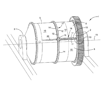
[0053] Referring to Figure 1, a typical grinding mill 1 comprises a milling
chamber or
body known as a "shell" 2 rotatably mounted on supports 3 via journal shafts 4
and
bearing assemblies (not shown). The mill shell 2 is made up of modular
components in
the form of individual mill shell sections 5 that are connected or joined
together.
Depending on the size of the mill shell, there may be between four, six or
eight shell
sections, with each shell section comprising one-half of the mill shell
diameter so that
two shell sections forming one half (lengthwise) of the mill shell. In other
configurations,
the mill shell can be split into two, three or four sections lengthwise and
then each of
those sections in 180 , 120 or 90 segments, respectively.
[0054] The mill shell sections 5 are generally arcuate or curved with
corresponding
arcuate or curved outer surfaces 10. The mill shell sections 5 are connected
or joined
via longitudinal flanges 11 and/or circumferential flanges 12 that
respectively extend
either along a longitudinal edge 13 or around an arcuate or curved edge 14 of
each
CA 02917059 2015-12-30
WO 2015/003208 PCT/AU2014/000700
- 9 -
shell section. Longitudinal flanges extend parallel to the longitudinal axis
15 of the mill
shell 2 when the mill shell is assembled. Circumferential flanges extend
around the
circumference of the mill shell when the mill shell is assembled. Respective
longitudinal
and circumferential flanges of adjacent shell sections 5 are aligned and then
connected
or joined together (typically using bolts or studs) to form a joint called a
"split flange" of
the assembled mill shell 2.
[0055] As best shown in Figure 1, frequently a split longitudinal flange 16
terminates
at a split circumferential flange 17 where three mill shell sections 5 are
connected
together along their respective longitudinal and circumferential flanges. This
creates a
"hard spot" generally indicated by 18, where there is a concentration of
stress due to the
sudden change in stiffness from the split longitudinal flange 16 to the split
circumferential flange 17 extending transversely to the split longitudinal
flange. A stress
distribution element in the form of a "dummy flange" 20 is provided according
to a first
embodiment of the present invention to alleviate the adverse effects of such
hard spots
by distributing the stress or load at the hard spot along its length, evenly
distributing the
load.
[0056] Referring to Figure 2A, the stress distribution element 20 is shown
in more
detail and comprises an elongated body 21 having a proximal end 22 for
connecting the
distribution element to the mill shell joint formed by the split longitudinal
flange 16 and
the split circumferential flange 17. The elongated body 21 also has a distal
end 23, and
varies in one dimension from the proximal end 22 to the distal end to
distribute stress
forces from the proximal end to the distal end. In this first embodiment, that
dimension
is the height 24 of the elongated body 21. In other words, the elongated body
21 has a
variable height 24 from the proximal end 22 to the distal end 23.
[0057] As best shown in Figure 2B, the elongated body 21 decreases in
height 24
from the proximal end 22 to the distal end 23. The decrease in height (and
hence
"thickness" in this dimension) can be achieved by step-wise decreases, smooth
transitions, gradual decreases or any combination of these options. Gradual
decreases
or smooth transitions can be either non-linear, such as a curved or arcuate
profile, or
linear, such as a taper. In this particular embodiment, the decrease in height
24 is a
mixture of both step-wise decreases and smooth transitions or gradual
decreases.
From the proximal end 22, a first portion or section 21a has an initial
maximum height,
followed by a non-linear decrease at a second portion 21b in the form of a
sinuous
CA 02917059 2015-12-30
WO 2015/003208 PCT/AU2014/000700
- 10 -
curve, then a third portion 21c of uniform height and finally a linear
decrease at a fourth
portion 21d in the form of a tapered portion.
[0058] As best shown in Figure 20, while the height 24 of the elongated
body 21
changes from the proximal end 22 to the distal end 23, the elongated body 21
still has a
substantially uniform thickness in its width 25.
[0059] As best shown in Figure 2B, the elongated body 21 at its proximal
end 23 and
a connecting side 27 are connected to a circumferential flange 28 of the mill
shell
section 5 (which is one half of a split circumferential shell section) and the
mill shell
section outer surface 10.
[0060] As best shown in Figure 1, the dummy flange 20 is connected to the
circumferential flange 28 so that it is located at or adjacent to a junction
between the
split longitudinal flange 16 and the circumferential flange 17. The dummy
flange 20 is
also arranged so that the elongated body 21 is coincident with the
longitudinal axis 29
of the split longitudinal flange 16, preferably by having its longitudinal
axis 29 in
alignment or coincident with the longitudinal axis of the split longitudinal
flange 16. The
structure of the dummy flange 20 with its variances in height results in a
controlled
stiffness that permits the dummy flange to evenly distribute the stress over
the joint
formed by the split longitudinal and split circumferential flanges, thus
effectively
removing or reducing the hard spot and redistributing the load (stress)
carried by the
split longitudinal flange 16.
[0061] Generally, the variances in height of the dummy flange 20 over its
length from
the proximal end 22 to its distal end 23 will depend on the stiffness of the
adjoining
geometry of the split flange, which may be unique for every combination of
mill
diameter, length, flange dimension and shell section thickness. However, the
geometry
of the dummy flange is preferably adjusted so that its stiffness reduces most
swiftly in
the unwelded areas or sections where higher stress can be accepted (generally,
the
"free", unattached or distal side opposite the connecting side 27, comprising
the curved
portion 21b, flat portion 21c and tapered portion 21d) and then blends
smoothly where
there is welding along its connecting side 27 and its proximal end 22. This
ensures the
load (stress) is distributed with efficient use of material. The height and
length (and
hence profile) can thus be modified or adjusted to accommodate the stiffness
of the
adjoining geometry of the joint formed by the split longitudinal and
circumferential
CA 02917059 2015-12-30
WO 2015/003208 PCT/AU2014/000700
- 11 -
flanges 16, 17. The inventors have discovered that the stiffness of the dummy
flange
20 (via its variable dimension such as height and/or width) can be balanced or
fine
tuned using advanced finite element analysis (FEA) techniques to achieve the
desired
even distribution of stress.
[0062] Referring to Figures 3A to 30, a second embodiment of the invention
in the
form of dummy flange 30 is illustrated where corresponding features have been
given
the same reference numerals. In this embodiment, the elongated body 31 has a
gradual decrease in the height from the proximal end 22 to the distal end 23.
There is
an initial maximum height 32 at a first portion 31a, followed by a smooth
transition to a
base 34 at a second portion 31b in the form of a curved, tapering portion, as
best
shown in Figure 3B. The width 25 is also substantially uniform along the
length of the
elongated body 31 from its proximal end 22 to its distal end 23, as best shown
in Figure
30.
[0063] Referring to Figures 4A to 40, a third embodiment of the invention
in the form
of dummy flange 40 is illustrated where corresponding features have been given
the
same reference numerals. In this embodiment, the elongated body 41 has a
combination of different gradual decreases in the height from the proximal end
22 to the
distal end 23. There is an initial maximum height 42 at a first portion 41a,
followed by a
non-linear decrease at a second portion 41b in the form of a sinuous portion,
then a flat
portion 41c and finally a tapered portion 41d, as best shown in Figure 4B.
Unlike the
previous two embodiments, the elongated body 41 also has a decreasing width 45
along its length from its proximal end 22 to its distal end 23, as best shown
in Figures
4A and 40. The elongated body 41 has an initial maximum width for portions 41a
and
41b. The elongated body 41 then narrows in width at portion 41c by way of a
curved
transition or taper. The same width is then maintained for the portion 41d.
[0064] Referring to Figures 5A to 50, a fourth embodiment of the invention
in the
form of dummy flange 50 is illustrated where corresponding features have been
given
the same reference numerals. In this embodiment, the elongated body 51 has a
gradual decrease in the height from the proximal end 22 to the distal end 23.
There is
an initial maximum height 52 at a first portion 51a, followed by a linear
decrease in the
form of a tapered portion, followed by a flat portion 51c and finally another
linear
decrease in the form of another tapered portion 51d, as best shown in Figure
5B. The
CA 02917059 2015-12-30
WO 2015/003208 PCT/AU2014/000700
- 12 -
width 55 is also substantially uniform along the length of the elongated body
51 from its
proximal end 22 to its distal end 23, as best shown in Figure 50.
[0065] The second, third and fourth embodiments work in the same way as the
first
embodiment described above and so will not be repeated. In other preferred
forms, the
elongated body has a step-wise decrease in the height of said elongated body
from the
proximal end to the distal end. This can take the form of a series of
descending step
portions from the proximal end to the distal end.
[0066] In another preferred form, the elongated body has a variable width
from the
proximal end to the distal end, similar to the decreases in width from the
proximal end to
the distal end in the third embodiment illustrated in Figures 4A to 40, but
with no
variation in its height.
[0067] Referring to Figures 6A to 6E, a fifth embodiment of the invention
is illustrated
where corresponding features have been given the same reference numerals. In
this
fifth embodiment, there is a plurality of dummy flanges 60 connected at their
respective
proximal ends 22 to the circumferential flange 28. The dummy flanges are
arranged so
that there are at least two dummy flanges of the same or equal length, with
dummy
flanges 60a being the same length, dummy flanges 60b being the same length and
dummy flanges 60c being the same length. Each pair of dummy flanges is also of
a
different length to the other pairs of dummy flanges. In this case, dummy
flanges 60a
are the longest, dummy flanges 60b are shorter in length and dummy flanges 60c
are
the shortest. Each pair of dummy flanges also has a variable height 24 but
uniform
width 25, as best shown in Figures 6B to 6E.
[0068] The dummy flanges 60a have an identical profile to the first
embodiment
illustrated in Figures 2A to 20 and so its description will not be repeated.
The dummy
flanges 60b gradually decrease in height, starting with a first portion 61a at
the proximal
end 22 that is followed by a sinuous or curved portion 61b, then a flat
portion 61c and
finally a curved portion 61d that terminates at the distal end 23. The dummy
flanges
60c decreases in height more rapidly than the other dummy flanges 60a, 60b due
to
their relative short length, having a first portion 61a at the proximal end 22
and then a
curved portion 61e that terminates at the distal end 23.
CA 02917059 2015-12-30
WO 2015/003208 PCT/AU2014/000700
- 13 -
[0069] The dummy flanges 60a, 60b, 60c are arranged so that the longest dummy
flanges 60a are substantially parallel to each other and are close or adjacent
to the hard
spot, where the split circumferential flange 17 (one half of which is formed
by the
circumferential flange 28) meets a split longitudinal flange 16. The other
dummy
flanges 60b, 60c of progressively shorter length are also arranged on either
side of the
dummy flanges 60a. This arrangement of the dummy flanges 60a, 60b, 60c further
distributes stress forces away from the hard sport and thus attenuate their
adverse
effects on the joint integrity.
[0070] A sixth embodiment of the invention is illustrated in Figures 7A to
7B, where
corresponding features have been given the same reference numerals. In this
sixth
embodiment, the arrangement of the dummy flanges 60a, 60b, and 60c of Figures
6A to
6E has been altered by removing one dummy flange 60a so that there are dummy
flanges 60b, 60c of progressively shorter length on either side of the dummy
flange 60a.
Again, the dummy flanges are arranged substantially parallel to each other and
close or
adjacent to the hard spot. In this case, the dummy flange 60a would be
situated so that
it is substantially aligned with the split longitudinal flange 16 that would
be formed on
the other side of the circumferential flange 28. That is, the dummy flange 60a
is
coincident with the longitudinal axis of the split longitudinal flange 16 (and
hence the
other dummy flanges 60b, 60c are parallel to this longitudinal axis).
[0071] An example of the second embodiment will now be described with
reference
to Figures 8A and 8B, where corresponding features have been given the same
reference numerals.
Example
[0072] Figure 8A shows the maximum stress range in a typical mill shell
joint 70
using FEA techniques. The joint 70 comprises a split longitudinal flange 16
that joins a
split circumferential flange 17, which is composed of two circumferential
flanges 28 of
adjoining mill shell sections 5. The hard spot 71 occurs at the junction of
the split
longitudinal flange 16 and split circumferential flange 17, where there is a
stress range
of about 85 MPa. The area 72 surrounding the hard spot has a stress range of
around
65 MPa.
CA 02917059 2015-12-30
WO 2015/003208 PCT/AU2014/000700
- 14 -
[0073] In comparison, Figure 8B shows the stresses where the dummy flange
20 is
connected to the joint 70. The stress range 75 in the weld radius, where the
hard spot
would have been is now about 52.5 MPa. The dummy flange 20 has distributed the
stress forces from the hard spot along its length such that there is a small
area 76
where the stress is about 80 MPa, comparable to the hard spot of Figure 8A,
but in an
area with no welds. Likewise, in the mill shell section 5 there is only a
stress range of
less than 30 MPa, away from the welded areas and where the allowable stress
range is
78MPa. Using the dummy flange thus results in a mill shell design that
complies with
the 53MPa allowable limit that is derived from British Standard 7608, but is
generally
accepted as an industry standard. Thus, the use of a dummy flange minimises
the risk
of hard spots increasing fatigue in the mill shell section, and hence mill
shell cracking
and failure. Accordingly, mill shell sections can be manufactured with a
reduced
thickness, reducing mill shell mass, associated manufacturing costs and
wastage of
material.
[0074] In each of the embodiments described above, the elongated body of
the
dummy flange has a rib-like or fin-like profile. However, other profiles can
be used,
such as a partly curved or sinuous profile, as best shown in Figures 9A and
9B. In
Figure 9A, the dummy flange 80 has an elongated body 80 with a partly curved
section
82, creating a partly curved profile. Similarly, in Figure 9B, the dummy
flange 84 has an
elongated body 85 with a sinuous portion 86, creating a partly sinuous
profile. In a
further preferred form as best shown in Figure 11, the dummy flange 100 has an
elongated body 21, similar to the above described embodiments, from which
extend
additional elongated bodies 101 of shorter length like branches from a tree
trunk. The
"branches" 101 can be arranged symmetrically about the "trunk" 21 (as shown by
the
lowest pair of branches in Figure 11) or offset to each other (as shown by the
highest
pair of branches in Figure 11).
[0075] In other preferred forms, the invention provides a stress
distribution assembly
for a joint of a mill shell, comprising a hub and a plurality of stress
distribution elements
of the first aspect of the present invention, wherein said hub is joined to
the respective
proximal ends of each said stress distribution element, said hub being
connectable to
said mill shell joint. In this preferred form, the hub acts as an intermediate
connecting
element to connect the stress distribution elements to the mill shell joint as
well as a
central connection for the stress distribution elements. The hub may be
substantially
linear and extend substantially orthogonal to the stress distribution
elements. As best
CA 02917059 2015-12-30
WO 2015/003208 PCT/AU2014/000700
- 15 -
shown in Figure 10A, the stress distribution assembly 90 has a linear hub 91
to which
the respective proximal ends 22 of the dummy flanges 60a, 60b, 60c of Figures
6A to
7B are connected, and the hub 91 is then connected to the circumferential
flange 28.
Alternatively, the hub is bulbous or semi-hemispherical, with the stress
distribution
elements extending divergently or radially outward from the hub, like rays
from the sun.
As best shown in Figure 10B, the stress distribution assembly 95 has a
hemispherical
hub 96 to which the respective proximal ends 22 of the dummy flanges 97 are
connected, with the hub 96 connected to the circumferential flange 28.
[0076] It will further be appreciated that any of the features in the
preferred
embodiments of the invention can be combined together and are not necessarily
applied in isolation from each other. For example, the stress distribution
system
illustrated in Figures 6A to 7B may have dummy flanges of different types
together,
such as the dummy flange 40 of Figures 4A to 40 having a reduced width and the
dummy flange 95 of Figure 10B having a partly sinuous profile.
[0077] Also, while the preferred embodiment of the invention have been
described in
relation to longitudinal and circumferential flanges of a mill shell, it will
be appreciated
that each of the aspects of the invention and the corresponding preferred
features are
also applicable to flanges, joints and other non-axisymmetric features on
other types of
constructions and structures, such as industrial kilns.
[0078] As used herein, unless otherwise specified the use of the ordinal
adjectives
"first", "second", "third", etc., to describe a common object, merely indicate
that different
instances of like objects are being referred to, and are not intended to imply
that the
objects so described must be in a given sequence, either temporally,
spatially, in
ranking, or in any other manner.
[0079] By providing a stress distribution element that reduces or
eliminates hard
spots that develop in the assembled mill shell, the invention ensures that
mill shells can
be designed with the optimum mill shell section thickness while still avoiding
the risks
associated with hard spots developing in the mill shell, thus minimising the
risk of mill
shell cracking and failure. Furthermore, as the mill shell section thickness
can be
optimised, the mill shell mass can be significantly reduced. There is also a
reduction in
manufacturing costs when using thinner mill shell sections and reduced wastage
of
material. Moreover, the profile of the stress distribution element in terms of
its variable
CA 02917059 2015-12-30
WO 2015/003208 PCT/AU2014/000700
- 16 -
dimension (be it height and/or width) can be tailored using FEA techniques to
different
stresses caused by different characteristics in particular mill shells due to
different
thicknesses in the flanges (or other non-axisymmetric features), different
materials of
the mill shell section and other physical parameters. Also, the stress
distribution
element can be readily retrofitted on existing mill shells. In all these
respects, the
invention represents a practical and commercially significant improvement over
the prior
art.
[0080] Although the invention has been described with reference to specific
examples, it will be appreciated by those skilled in the art that the
invention may be
embodied in many other forms.