Note: Descriptions are shown in the official language in which they were submitted.
CA 02917157 2016-01-08
LOW-FREQUENCY RECEIVING FOR RADIO FREQUENCY
IDENTIFICATION
BACKGROUND
[0001] Radio frequency identification (RFID) systems have been used to
track
inventory, such as in a store. The inventory amount can be reduced as items
containing
RFID tags pass an RFID interrogator at time of purchase, for example. RFID
tags can be
either passive or active.
[0002] Passive RFID tags are interrogated with a radio frequency power
source that
bounces off of the passive tags, where the return signal uniquely identifies
the tagged
object with an RFID identifier (ID). In contrast, active RFID tags contain a
power source
(usually a battery) and can radiate an identifying radio signal, and are also
known as
RFID transmitter tags. A reader can receive and record such a signal, thus
identifying the
tagged object. Because passive tags have no power source, interrogating
readers need to
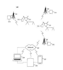
be in relatively close proximity to interrogate and read the passive tags.
More expensive
active tags, however, can be read from a greater distance, but which still has
distance
limits (such as within a few hundred meters depending on the power source).
[0003] Radio frequency ID tags are used in other industries as well. An
RFID tag
attached to an automobile during production can be used to track its progress
through the
assembly line. Pharmaceuticals can be tracked through warehouses. Even
livestock and
pets can have tags injected to facilitate positive identification of animals.
BRIEF DESCRIPTION OF THE DRAWINGS
[0004] A more particular description of the disclosure briefly described
above will be
rendered by reference to the appended drawings. Understanding that these
drawings only
provide information concerning typical embodiments and are not therefore to be
con-
sidered limiting of its scope, the disclosure will be described and explained
with
additional specificity and detail through the use of the accompanying
drawings.
[0005] Figure IA is a system diagram of long-range radio frequency
identification
(RFID) of assets using multiple RFID transceivers, according to one
embodiment.
[0006] Figure 1B is a system diagram of an example RFID tag used in the
system of
Figure 1A, according to one embodiment of the present disclosure.
1
CA 02917157 2016-01-08
[0007] Figure 2 a system diagram of radio frequency identification of
moving assets
using a mobile RFID receiver, according to another embodiment.
[0008] Figure 3 is a photo of the high-power interrogator of Figure 2,
indicating use of
three omnidirectional antennas.
[0009] Figure 4 is a system diagram of radio frequency identification of
moving assets
using a hand-held RFID tracker, according to another embodiment of the present
disclosure.
[0010] Figures 5A, 5B, 5C and 5D are several perspective views of the hand-
held
RFID tracker of Figure 4, according to one embodiment.
[0011] Figure 5E is a system diagram of the components and functionality of
the
hand-held RFID tracker of Figure 4, according to one embodiment of the present
disclosure.
[0012] Figure 6A is a photo of a hand-held RFID receiver using a split-beam
antenna,
according to one embodiment.
[0013] Figure 6B is a photo of the hand-held interrogator of Figure 6A,
with a close-
up view of a control interface and display.
[0014] Figure 7 is a perspective view of an RFID tag housing according one
embodiment of the present disclosure.
[0015] Figure 8 is a top perspective view of the RFID tag housing of Figure
7.
[0016] Figure 9 is a side perspective view of the RFID tag housing of
Figure 7.
[0017] Figure 10 is a flow chart of a method for determining an asset
location from a
distance of an asset tagged with an RFID tag using the system of Figure 1A,
according to
one embodiment of the present disclosure.
[0018] Figure 11 is a flow chart of a method for aggregating and mapping
historical
tag history in a user interface, according to one embodiment of the present
disclosure.
[0019] Figure 12 illustrates a computer system, which can represent any of
the
computing devices referenced herein.
DETAILED DESCRIPTION
[0020] By way of introduction, the present disclosure explains that a radio
frequency
identification (RFID) tag can be woke up through a low-frequency signal and
can
communicate with other RFID readers in the vicinity, to help determine and
track
2
CA 02917157 2016-01-08
locations of RFID tags. A RFID transceiver can send a wake up signal through
the low-
frequency signal to such RFID tags, and can also send other commands or
information
through high-frequency signals to direct the RFIDS tags once the RFID tags are
awake.
[0021] The present disclosure further explains how assets such as those
found on a
farm or ranch, on railcars or on transport trucks, for example, can be
monitored and
tracked over time in relation to inventory and environmental conditions
through the RFID
tags. For example, data (both tag-related and environmental-related data) from
the RFID
tags on such assets can be collected with transceivers and provided to a user
who can
make a decision regarding the assets based on the presented data. As some
assets can be
far reaching and take paths over a wide area, certain algorithms and methods
are
employed to detect the RFID tags on the assets, determine where the assets are
located
during which periods of time, and provide path or heat signature graphs on
maps
indicative of historical movement of each asset of interest. Trends can be
established,
which when varied from, can be indicative of health problems or other issues
that can be
flagged before becoming a real threat (like a diseased cow, for example).
[0022] In one embodiment, an RFID tag includes a power source and a
transmitter to
transmit a unique identifier. The tag also includes a receiver operatively
coupled to the
transmitter and to receive low-frequency signals from an active RFID
transceiver located
within a vicinity of the receiver, e.g., within tens of feet away. The
transmitter is activated
by the power source responsive to the receiver receiving a wake up command at
a
predetermined low frequency. For example, the frequency of the wake up command
can
be about 150 KHz or less.
[0023] In another embodiment, a RFID transceiver includes an antenna and
non-
transitory computer-readable medium storing instructions. The RFID transceiver
can also
include a transmitter to transmit low-frequency signals to RFID tags through
the antenna,
and a processing device operatively coupled to the transmitter. The processing
device can
execute the instructions to insert a station identifier (ID) into the low-
frequency signals
that direct the RFID tags to retransmit the station ID, wherein the station ID
identifies an
approximate location of the RFID tags that are located in the vicinity of the
RFID
transceiver.
3
CA 02917157 2016-01-08
[0024] Figure 1A displays a system 100 for long-range radio frequency
identification
(RFID) of assets 110 using multiple transceiver towers 120 (also referred to
herein as
transceivers 120), which can also be mobile RFID transceivers 220 (Figure 2)
or hand-
held trackers 420 (Figure 4). Each asset 110 can be an animal (such as
livestock),
equipment (such as a tractor, all-terrain vehicle (ATVs), farm vehicles,
computers and the
like), fence posts and irrigation components, and other such assets. Each
asset 110 can be
tagged with an RFID transmitter tag 112 capable of transmitting at long
distances as well
as at shorter distances. The RFID transmitter tags 112 will alternatively be
referred to
herein as RFID tags 112 or simply as tags 112.
[0025] Figure 1B is a system diagram of an example RFID tag 112 used in the
system
100 of Figure 1A. The RFID tag 112 can include an antenna 152, a
microprocessor 158
(also referred to herein as simply a processor 158), a transmitter 160, a
receiver 162,
computer storage 164, memory 166, a battery 168 and one or more sensors 170.
The
RFID tag 112 can be intelligent, e.g., capable of sending and or/receiving
radio signals at
different frequencies for different purposes (or different assets) and capable
of storing
collected data for retrieval by the system 100 at a later time. The RFID tag
112 can also
process the data using the microprocessor 158 and the memory 166. The RFID tag
112
can be powered by the battery 168 or other electrical energy storage or
conversion system
(such as solar), and can transmit spontaneously, e.g., the RFID transmitter
tags 112 need
not be activated by a reader system or interrogator to initiate transmission.
The RFID tag
112 can also be turned on or signaled remotely by an interrogator or RFID
transceiver as
will be discussed in more detail. The sensors 170 can gather environmental
information,
which can include temperature, blood pressure or other vital signs of an
animal, and the
like. Such environmental data can also be stored in the computer storage 164
of the tag.
[0026] The receiver 162 can detect signals at short ranges but consume
significantly
less power than an active RFID signal receiver (such as the transceivers 120
of Figure 1A,
for example). Accordingly, the receiver 162 can be turned on for much longer
time
periods without draining the battery 168 of RFID tag. The receiver 162 can be
activated
with a low duty-cycle command (e.g., less than 50% duty cycle) so that it is
off more of
the time to reduce power consumption. As a result, the probability of the RFID
tag 112
detecting a low-frequency signal transmission can be much higher than the
probability of
4
CA 02917157 2016-01-08
detecting an active RFID signal transmission at a high frequency. This makes
the low-
frequency signal transmission useful for generating low-latency responses from
RFID tags
at shorter ranges because command signals do not need to be resent many times
to
increase the probability of detection at the RFID tag.
[0027] More particularly, the RFID tag 112 can respond to low-frequency
signal
detection by processing data in the signal, executing pre-stored instructions,
sending an
active RFID transmission, or changing its behavior (such as to transmit at a
different
frequency for a period of time, transmit less frequently or transmit more
frequently). In
one embodiment, an RFID tag 112 receives a unique identifier (ID) such as a
station ID in
a low-frequency signal from one of the RFID transceivers 120 located within a
close
range (within tens of feet and less than a mile, for example). In one
embodiment, the low-
frequency is around 150 KHz or less and may depend on application.
[0028] The RFID tag 112 can detect the station ID in the low-frequency
signal and
treat the station ID as a wake up command. The RFID tag 112 can then become
activated
with the battery powering its several components, and begin transmitting the
station ID of
the transceiver that placed the RFID tag 112 into the active state. The
station ID can be
packaged in a special packet type readable by other RFID reading devices.
Accordingly,
these other RFID reading devices in the vicinity of the RF1D tag 112 can
detect the
station ID and mark the RFID tag 112 as being at a location near the
transceiver 120
carrying the station ID. The RFID transceivers 120 can also record the wake up
of the
RFID tag 112, and track its location. The RFID transceivers 120 can further
communicate
with or read the RFID tag 112 using an electromagnetic field. Accordingly, the
RFID tag
112 may be a combination of a passive and an active RFID tag, and able to act
as both
depending on the conditions and the commands received from the RFID
transceivers 120.
[0029] The signal transmission of the RFID transceivers 120 can further
include high-
frequency (or ultra-high frequency) signals such as between 14 MHz and 960
MHz, for
example, which can be modulated with data to contain commands to the tag,
information
about the identity of the activating transmitter, or other sensory data. This
allows the
RFID tags 112 to receive a wake-up command from a low-frequency activation
signal
and other data from high-frequency signals that can be processed as commands
or used to
generate unique responses after the RFID tag has awakened.
CA 02917157 2016-01-08
[0030] Accordingly, the RFID tags 112 can be activated with a low-frequency
signal
transmission containing the station ID and a short transmission radius to
immediately
produce an active RFID transmission from a single RFID tag. The active RFID
transmission response can include the station ID from the low-frequency signal
transmission to indicate that it is located in close proximity to an
activating station, such
as to the RFID transceiver towers 120, multiple mobile RFID transceiver 220
(Figure 2),
or to a hand-held tracker 420 (Figure 4), which will be discussed in more
detail. When the
activating station position is known, this information can be used to detect
the presence of
an RFID tag 112 in a known, precise location.
[0031] In one embodiment, a close range RFID transceiver (such as the RFID
mobile
transceiver 220 or the hand-held tracker 420) can send the low-frequency
activation
signal that wakes up a tag while a long range RFID transceiver (such as the
RFID
transceiver tower 120 or the RFID mobile transceiver 220) can send the high-
frequency
signals that can carry other data and commands, and to also track the location
of the tag.
[0032] The transmission power level of the low-frequency signal from the
RFID
transceivers 120, 220 or 420 can be reduced to cover a small area such as a
doorway,
gate, animal chute, scale or a measurement device. For example, low-frequency
activation
used in close proximity to measurement devices such as scales, food, water,
medication,
or nutritional supplement dispensers can uniquely link the measurement to a
unique RFID
to identify the animal that is being measured, fed, or treated.
[0033] The transmission power level of the low-frequency signal can be
increased to
cover a wider area such as a pen, alley, or pasture section. The range of low-
frequency
signal detection is a combination of the transmitter power and antenna gain
and the
sensitivity of the receiver 162. Low-frequency activation of RFID tags 112 can
be used to
count or collect inventory of tagged animals in feedlots, auction houses,
loading or
unloading lanes wide enough for multiple animals to pass at once, holding
pens, at
premise entrances or exits where move-in/move-out records are desired. The
high
probability of low-frequency detection and long-range ability of active RFID
transmission
can produce very efficient and reliable inventory and counting of RFID tags
112. This is
the case at least because there is much more interference at high frequencies
that are used
6
CA 02917157 2016-01-08
for many more modern day applications. Low frequency bands, on the other hand,
are not
as overwhelmed by interference and therefore attenuate less quickly.
[0034] Because the active RFID transmission range is much farther than that
of
traditional RFID tags in a passive state, the active RFID transceivers 120,
220, 420 can be
located farther from the RFID tags 112 than a low-frequency transmitter and
can cover a
much larger area. This reduces the cost and simplifies complexity of the
system 100 by
reducing the number of RFID transceivers and eliminates the need to deploy
transceivers
in a low-frequency activating station or to connect data cables or wireless
backhaul
datalinks to low-frequency activating stations.
[0035] With further reference to Figure 1A, there are preferably more than
one RFID
transceiver 120 so that the greatest number of assets can be tracked over the
greatest
distance. The RFID transceivers 120, 220 and 420 can include a coupled
processing and
storage unit 114 that can analyze collected RFID and environmental data, and
store the
data before the data is sent to system computing devices over a network 130.
The network
130 can be cellular, wireless, wired or a combination of all three, as will be
discussed in
more detail. The computing devices can include mobile devices 122 (such as a
smartphone, tablet, etc.), a computer 126 (such as a desktop or laptop
computer) and other
display and/or audio devices 124 capable of announcing or presenting the
tracked data to
users of the system 100. The display and/or audio devices 124 can be coupled
to or in
communication with a mobile device or a computer.
[0036] The RFID transceivers 120, 220 and 420 can include event-timing
resources
that measure the time of arrival (TOA) of RFID tag transmissions from the RFID
tags 112
with known locations, timings, and timing offsets. Alternatively, or
additionally, the
RFID transceivers 120, 220 and 420 can include one or more processors or other
logic for
acquiring and/or computing the angle of arrival (AOA) to the receiver of the
RFID signal
originating from RFID tags 112.
[0037] With the TOA and/or the AOA, the processing and storage units 114
can
determine the location of the RFID tags 112, or this information can be sent
to the
computing devices 122 and/or 126 that in turn determine the location of the
RFID tags
112. Along with sensor and environmental data, the historical locations
tracked over time
can demonstrate trends, behaviors, motion, dwell, entrance, exit,
environmental
7
CA 02917157 2016-01-08
conditions, and other such information about each asset 110 corresponding to
respective
RFID tags 112. As will be discussed, these trends can be provided in an
accessible
manner for users to notice and to take action depending on any disturbing
trends or
anomalies on previous trends.
[0038] The RFID tag 112 can transmit an identifying packet approximately
once a
minute. At least three RFID transceivers 120, 220 or 420 can be placed
strategically about
an area of interest. The RFID transceivers can measure the time of arrival
(TOA) of the
transmission to the receiver. Processing electronics of the RFID transceivers
120, 220 or
420 can be in communication with timing information given by an attached
global
positioning system (GPS) receiver that is adapted to track time and location.
In this way,
each receiver can obtain access to accurate global time. The TOA information
and the
identifying number from a tag transmission can be combined and sent to an
application
server, such as the computer 126 in Figure 1A.
[0039] The application server can use the timing information from the three
RFID
transceivers, map elevation data, and the speed of radio waves to
mathematically
determine the location of the RFID tag and therefore the attached asset 110.
The RFID tag
112 can also transmit additional desired status information to the
transceivers 120, 220 or
420. The server can log the location and status information and present the
data on
webpages or computer applications for users to access, e.g., in reports and/or
on a map of
the desired area as will be explained in more detail.
[0040] One method of determining the location of an RFID tag 112 from three
or
more transceivers is as follows. Let [tRi, tR2, tR3, tRN] be
the time of arrival at towers 1
through N that are located at r, = [r1õ, riy, r,d, where coordinates ri, r2,
r3, rN are included
in an elevation map giving the elevation coordinate at every (x, y) position
defined by
felevatton(X,y) = Z. The steps of the method can include the following steps,
without
limitation:
[0041] 1) Compensate for any known time bias in the tower time of arrivals,
[tbi, tb2,
tb3,... tbNi, e.g., timestamps = [tR1, tR2, tR3, tRN] [tbl, tb2, tb3,..
= tbN]=
[0042] 2) Remove large time offsets in this compensation to create small
time
differences near zero, e.g, timestamps = timestamps ¨ minimum ([tRi, tR2, tR3,
tRN]). In
this context, minimum refers to the earliest time of arrival at one of the
towers and is
8
CA 02917157 2016-01-08
determined by comparing arrival times with other towers. By removing this
minimum
time (essentially setting it to 0), the location of the tag can be determined
using the
remaining two variables instead of all three time offsets, which simplifies
the processing.
In other words, choose tR, such that tR, is less than or equal to any of tRi,
tR2, tR3,
[0043] 3) Convert time differences to distance differences using speed of
signal
propagation, e.g., c_timestamps = [tRi, tR2, tR3, tRN] * c
= [c*tRi, c*tR2, c*tR3, c*tRN]
where c is the speed of light/signal propagation.
[0044] 4) Initialize solution parameter set beta = [x, y, c*ts] where (x,
y) are solution
coordinates and ts is the time at which the signal transmission is sent, and
where beta =
[xo, yo, 0] where xo, yo are chosen nearby the expected solution area. For
example, xo, yo
can be chosen as the coordinates of one of the towers or the average of all
the tower
coordinates.
[0045] 5) Find the values of beta = [x, y, c*ts] that minimize the cost
function f as
follows:
beta = [x, y, c*ts] = arg min(f)
f= sum(fi A 2) is the sum of the squares of f, cost components from each of N
towers.
Z = felevatton(X,Y) = Z is the elevation at coordinates (x,y) from the
elevation map.
fi = sqrt( (rix ¨ x) A 2 + (riy y) A 2 + (riz ¨ z) A 2 ) ¨ (c*tR,- c*ts ) is
the error
between the distance from solution coordinates (x, y, z) and tower i
coordinates and the
signal propagation distance during the time interval from ts to tRi.
[0046] 6) The RFID tag location can be given by coordinates x, y, and z= f
-elevation(X,
y)=
[0047] Figure 2 displays a system 200 of radio frequency identification of
assets
(similar to that of Figure lA but) using a mobile RFID transceiver 220, a
photo of which
is shown in Figure 3. The RFID receiver 220 can include multiple antennas 221
for
receiving signals from the RFID transmitter tags 112.
[0048] The RFID transceiver 220 can be attached to the top of an ATV or
other
vehicle, which can travel around the area of interest to collect RFID signals
on a
continuous basis. The RFID transceiver 220 can be deployed in multiples as
well and can
take the place of the RFID transceiver towers 120 where such towers have not
yet been
9
CA 02917157 2016-01-08
put in place, or are out of range of a certain area of interest. The RFID
transceiver 220 can
include or be coupled with a processing and storage unit 214 such as the
storage unit 114
discussed with reference to the RFID transceiver towers 120.
[0049] To determine location, the RFID transceiver 220 can include a GPS
device or
capability and an inertial measurement unit (IMU), a gyroscope and/or
accelerometer(s)
(as does the hand-held tracker 420 discussed in Figure 5E) to be able to
continuously
know its own location and orientation while receiving RFID tag signals, and
compensate
for its location and direction of travel to determine positions of the RFID
tags 112. The
RFID transceiver 220 can determine the angle of arrival (AGA), which is the
direction of
the incoming RFID signal relative to the multiple antenna array 221. The RFID
receiver
220 can further determine the heading (direction of the multiple antenna array
relative to
north), and calculate a bearing angle from the RFID transceiver 220 to the
RFID signal
relative to north. The RFID transceiver 220 can also determine the signal
power level of
an incoming RFID signal and calculate a maximum range estimate from a path
loss
equation. The bearing angle and its uncertainty define an angular sector in
which the
RFID tag is positioned with the range limited by the maximum range estimate.
The
observations of bearing angle and/or maximum range are recorded from multiple
locations relative to the RFID transceiver 220. The locations and bearing
angles and/or
maximum ranges of multiple observations of the RFID tags 112 can be combined
to
determine the position of the RFID tags.
[0050] Figure 4 displays a system 400 of radio frequency identification of
assets using
a hand-held RFID tracker 420. In this embodiment, instead of RFID transceiver
towers
120 or mobile RFID transceivers 220 mounted to vehicles, user(s) can use one
or more
hand-held RFID trackers 420 to detect and receive RFID signals from the RFID
transmitter tags 112 associated with corresponding assets 110.
[0051] A user of each hand-held RFID receiver 420 can sweep from right to
left and
up and down to be pointed towards the assets 110 in the area of interest. The
data can
then be processed within the hand-held RFID tracker 420 to determine the
locations and
specific information with relation to the assets 110, or can alternatively
send the RFID
data received in the RFID signals to the computing systems 122, 124 and/or
126, which
can then make the location determinations.
CA 02917157 2016-01-08
[0052] Figures 5A, 5B, 5C and 5D are several perspective views of the hand-
held
RFID tracker 420 of Figure 4. Figure 5E is a system diagram of the components
and
functionality of the hand-held RFID tracker 420. The hand-held RFID
transceiver 420 can
include a directional antenna 522 attached to a handle 524 and to an interface
unit 528.
The interface unit 528 can further include a display 532 for viewing and
controlling
settings and to view RFID data as it is received in RFID signals from the
assets 110.
100531 The interface unit 528 and/or the handle 524 can include the
electrical
components of the hand-held RFID transceiver 420, shown in detail in Figure
5E. The
hand-held RFID tracker 420 can include an RFID transceiver 534, a network
interface
536, a rechargeable battery 538, an audio speaker 540, a microprocessor 542
and other
electronics for interfacing with the antenna 522 and for determining location
information
for RFID transmitter tags 112 for which RFID signals are received. The hand-
held RFID
tracker can further include a data transfer connection 544 (e.g., for direct
physical data
transfer to a computing device), a network interface 546, a wireless
connection 548, and a
wired connection 550 for interfacing with the network 130. The hand-held RFID
tracker
420 can further include a satellite positioning receiver 553, an inertial
measurement unit
(IMU) 554, a gyroscope 556 and/or an accelerometer 558 to aid in determining
positioning and orientation information with relation to the assets 110 in the
area of
interest. The hand-held RFID tracker 420 can further include computer storage
564 and
memory 566 for storing the RFID data (including location information) in the
hand-held
RFID receiver 420.
[0054] The directional antenna 522 can be configured to communicate through
the
network 130 and to transmit collected data and other information to the
computing
systems 122, 124 and/or 126. The hand-held RFID tracker 420 can further
include a low-
frequency transmitter (e.g., as part of the transceiver 534) for producing
highly-
responsive, short-range activation signals which can be received by an RFID
tag. The
transceiver 534 can transmit RFID tag command signals, record and display the
RFID
number and signal strength of RFID tag transmissions, and store the timestamp
and data
contents of RFID tag transmissions in the storage 564 for subsequent retrieval
and
processing.
11
CA 02917157 2016-01-08
[0055] The hand-held RFID tracker 420 can send command signals to the RFID
tags
112 to change behavior of the RFID tags. For example, RFID tags which are
being
tracked can be commanded to transmit more frequently for a period of time to
increase
the number of tracking observations available to the user on the handheld
tracker display
532. Also, RFID tags that are being recorded into an inventory list can be
commanded to
transmit more frequently and then commanded to stop reporting once the
transmissions
are successfully recorded.
[0056] By way of example, the RFID tags 112 can be commanded to enter a low
power storage mode, which disables all transmissions to conserve tag battery
and keep
only the RFID tag receiver active to detect subsequent command signals. RFID
tags can
be commanded to wake up from low power storage mode and re-enable their RFID
signal
transmissions. RFID tags can be commanded by a uniquely identified station
with a
known signal activation radius to respond with the unique station ID in their
RFID signal
transmission to indicate that the tags are inside the proximity of the signal
activation
radius of the known station location. Command signals can be uniquely
addressed to
particular RFID tags (with specified unique IDs) so that the commands are
ignored by
RFID tags that do not match the RFID number in the command. Command signals
can
also be globally addressed so that all RFID tags that receive the command will
respond to
the command. Tag commands can contain a time duration that instructs RFID tags
to
change their behavior for a specific length of time before returning to their
default
behavior as before receiving the command.
[0057] To find an individual tag, the hand-held RFID tracker 420 can
alternate
between transmitting a rapid series of tag wakeup command signals and
listening to
receiver RFID tag transmissions. The tag wakeup command signal commands the
tag
with a RFID identifier matching the RFID identifier in the command signal to
increase its
RFID signal transmission rate for a specified period of time. RFID
transmissions from the
matching RFID tag can be displayed with their received signal strength and an
audio
sound can be generated to indicate the relative strength of the received
signal and whether
the matching RFID tag is relatively near or far from the hand-held RFID
tracker.
[0058] After the hand-held RFID tracker 420 receives RFID tag transmission
confirming that the wakeup command has been received, the wakeup commands can
be
12
CA 02917157 2016-01-08
transmitted less frequently to allow the receiver to spend more time listening
for RFID
signal transmissions. Additional wakeup commands can be sent to renew the
wakeup
command interval to maintain the RFID tag's increased transmission rate and
prevent the
tag from returning to its default, slower rate of transmission. The user can
point the hand-
held tracker 420 in various directions to respond to the direction and
strength of RFID
signal transmissions that identify the direction of the matching RFID tag and
move
towards the tagged asset 110 until the matching RFID tag is visually located.
[0059] The directional antenna 522 can receive RFID tag transmissions that
arrive at
the hand-held RFID tracker 420 from an angular sector centered in the
direction that the
tracker is pointed. RFID tag transmissions that arrive at the hand-held RFID
tracker 420
from directions outside the directional antenna beam width are not received. A
wide
directional beam improves the speed of finding the direction of an RFID signal
transmission when searching in all directions. A narrow directional beam
improves the
precision of identifying the direction of the RFID transmission. The
directional antenna
beam width can be selected with an intermediate value to balance search speed
and
directional precision.
[0060] The hand-held RFID tracker 420 can record the timestamp and contents
of a
RFID signal transmission. The RFID tracker can process the records to collect
summary
statistics such as total read count, read count per RFID, maximum or minimum
or average
receive strength, and RFID tag sensor data. The RFID signal timestamps,
contents, and
statistics can be subsequently retrieved and processed to record inventory,
generate
reports of animals moving in or out of a premises, or stored in a database.
[0061] Figure 6A is a photo of a hand-held RFID transceiver 620 using a
split-beam
antenna 618. The split-beam antenna 618 can include a reflector 622, a first
antenna array
634 and a second antenna array 636, among other features. The hand-held RFID
transceiver 620 can include an interface unit 622 and a handle 624. The
interface unit 622
can further include a control legend 629 and a control interface 640 along
with a display
632 (see Figure 6B). The control interface 640 is configured to receive user
control
inputs according to menu options displayed on the control legend 629. The
interface unit
622 can otherwise operate similarly to the interface unit 522 of Figures 5A,
5B, 5C and
5D.
13
CA 02917157 2016-01-08
[0062] Figures 7 through 9 include views of an RFID tag housing 700 for
housing the
RFID transmitter tags 112 described herein. The RFID tag housing 700 can
include a
staged housing 702 configured at varying widths to conform to a size and shape
of the tag
112. The housing 700 can further include a head 704 having a neck 708 and an
aperture
712 including multiple hinged tabs 714. The hinged tabs 714 can be biased to
grab onto
an asset identifier tag (e.g., that includes a visual identification number)
to which the
RFID housing 700 can be attached. The aperture can be reinforced with a ring
718, which
can also provide additional strength to the hinged tabs 714.
[0063] Figure 10 is a flow chart a method for determining an asset location
from a
distance of an asset 110 tagged with an RFID tag 112 using the system 100 of
Figure 1A.
The method can begin with retrieving arrival times as time stamps for each
RFID
transceiver tower 120 (1005). The method can continue with setting the
smallest (or
oldest) time stamp to zero for a first (usually nearest) tower (1010). The
method can
continue with removing this first tower's time stamp from the arrival times of
the other
towers to create time offsets for the other towers (1015) and converting the
time offsets to
distance using time of flight for the speed of light (1020). The method can
continue with
using the converted distance as a radius distance from the corresponding tower
120
(1025).
[0064] The method of Figure 10 can continue with incrementing the radius of
each
tower (1030) and checking for an intersection on all circles formed by the
radii (1035).
The method can continue with determining whether an intersection of the radii
occurs
(1040). If there is no intersection, the method continues back to incrementing
the radius
of each tower (1030) and checking for an intersection on all circles formed by
the radii
(1035).
[0065] When at least three intersections do occur (1040), the method
continues with
comparing distances from each intersecting point to find the closest three
intersections
(1045). The method can continue with averaging intersection distances and
checking that
the average is below an allowable threshold distance (1050). The method can
then
determine whether the average is acceptable by accepting average intersection
distances
below the pre-determined threshold (1055). When the average is not acceptable,
the
method returns to steps 1030 and 1035 as before, continuing to form radii
distance from
14
CA 02917157 2016-01-08
the towers. If the average is acceptable, the method can compute the central
location
between points for the final location of the asset (1060).
[0066] The method of Figure 10 can also be used with mobile RFID
transceiver 220
and 420, but as discussed herein, additional calculations can be required to
account for the
movement of the RFID receivers themselves during the process of acquiring
location data
and determining the location of the tags.
[0067] Figure 11 is a flow chart of a method for aggregating and mapping
historical
tag history in a user interface. The method can be executed by a processing
device of one
or a combination of the computing devices 122, 124 or 126. The method can
begin with
requesting a tag history or an analysis based on the tag history (1110). The
method can
then decide whether the requested tag history is for multiple days or a single
day (1120).
If the answer is yes, the request is for a multi-day history, the method can
aggregate
location data into 1440 points, which is the number of minutes in each day
(1130). In this
way, changes made from minute to minute will show up in the tag history data
and be
capable of being mapped over time. The method can then create 1440 bins and
place "n"
number of minutes into each bin (where n equals the day count requested)
(1140). If only
one day's worth of history is requested (1120), the method can go straight to
receiving the
tag history data from the processing system performing the tag history
analysis for that
day (1150). Otherwise, binned tag history data is received for all of the
multiple selected
days (1150).
[0068] The method can continue by deciding whether the user has selected
the heat
map or the paths as a way to display the binned tag history data (1160). When
the user
selects (through the user interface) to display the heat map, then the method
formats the
data into a color-coded area on the map corresponding to historical movement
of the asset
(1170). Otherwise, when the user selects (through the user interface) to
display paths, the
method formats the data into distinguished paths on the map corresponding to
specific
paths taken by the asset during the selected period (1180).
[0069] Since a tag 112 can be assigned an "object" or simply be read as a
tag,
grouping and tracking systems can process data in relation to "objectivized"
tags.
Location-based tag information may only be available on the tag while metadata
can be
stored on an "object," for example. The object can then be tied to the tag and
contain any
CA 02917157 2016-01-08
information outside of location data. This enables the object to use multiple
tags over its
lifespan and tags can also reference multiple objects. More than one visual
interaction
algorithms can run on an object, resulting in various processed data. The
processed data
resulting from the executed algorithms can then be melded together to show
current
locations for a tag and any metadata that is available.
[0070] Figure 12 illustrates a computer system 1200, which can represent
the systems
100, 200 and 400 disclosed with reference to Figures 1, 2 and 4, or any other
computing
devices referenced herein for execution of the disclosed methods and
algorithms, which
when so implemented, can be a special purpose computer. The computer system
1200 can
include an ordered listing of a set of instructions 1202 that can be executed
to cause the
computer system 1200 to perform any one or more of the methods or computer-
based
functions disclosed herein. The computer system 1200 can operate as a stand-
alone
device or can be connected to other computer systems or peripheral devices,
e.g., by using
a network 130.
[0071] In a networked deployment, the computer system 1200 can operate in
the
capacity of a server or as a client-user computer in a server-client user
network
environment, or as a peer computer system in a peer-to-peer (or distributed)
network
environment. The computer system 1200 can also be implemented as or
incorporated into
various devices, such as a personal computer or a mobile computing device
capable of
executing a set of instructions 1202 that specify actions to be taken by that
machine,
including and not limited to, accessing the interne or web through any form of
browser.
Further, each of the systems described can include any collection of sub-
systems that
individually or jointly execute a set, or multiple sets, of instructions to
perform one or
more computer functions.
[0072] The computer system 1200 can include a memory 1204 on a bus 1220 for
communicating information. Code operable to cause the computer system to
perform any
of the acts or operations described herein can be stored in the memory 1204.
The memory
1204 can be a random-access memory, read-only memory, programmable memory,
hard
disk drive or any other type of volatile or non-volatile memory or storage
device.
[0073] The computer system 1200 can include a processor 1208, such as a
central
processing unit (CPU) and/or a graphics processing unit (GPU). The processor
1208 can
16
CA 02917157 2016-01-08
include one or more general processors, digital signal processors, application
specific
integrated circuits, field programmable gate arrays, digital circuits, optical
circuits, analog
circuits, combinations thereof, or other now known or later-developed devices
for
analyzing and processing data. The processor 1208 can implement the set of
instructions
1202 or other software program, such as manually-programmed or computer-
generated
code for implementing logical functions. The logical function or any system
element
described can, among other functions, process and/or convert an analog data
source such
as an analog electrical, audio, or video signal, or a combination thereof, to
a digital data
source for audio-visual purposes or other digital processing purposes such as
for
compatibility for computer processing.
[0074] The computer system 1200 can also include a disk or optical drive
unit 1215.
The disk drive unit 1215 can include a computer-readable medium 1240 in which
one or
more sets of instructions 1202, e.g., software, can be embedded. Further, the
instructions
1202 can perform one or more of the operations as described herein. The
instructions
1202 can reside completely, or at least partially, within the memory 1204
and/or within
the processor 1208 during execution by the computer system 1200. Accordingly,
databases configured to store data generated from execution of the disclosed
methods and
algorithms can be stored in the memory 1204 and/or the disk unit 1215.
[0075] The memory 1204 and the processor 1208 also can include computer-
readable
media as discussed above. A "computer-readable medium," "computer-readable
storage
medium," "machine readable medium," "propagated-signal medium," and/or "signal-
bearing medium" can include any device that includes, stores, communicates,
propagates,
or transports software for use by or in connection with an instruction
executable system,
apparatus, or device. The machine-readable medium can selectively be, but not
limited to,
an electronic, magnetic, optical, electromagnetic, infrared, or semiconductor
system,
apparatus, device, or propagation medium.
[0076] Additionally, the computer system 1200 can include an input device
1225,
such as a keyboard or mouse, configured for a user to interact with any of the
components
of system 1200. It can further include a display 1230, such as a liquid
crystal display
(LCD), a cathode ray tube (CRT), or any other display suitable for conveying
information. The display 1230 can act as an interface for the user to see the
functioning of
17
CA 02917157 2016-01-08
the processor 1208, or specifically as an interface with the software stored
in the memory
1204 or the drive unit 1215.
[0077] The computer system 1200 can include a communication interface 1236
that
enables communications via the communications network 130. The network 130 can
include wired networks, wireless networks, or combinations thereof. The
communication
interface 1236 network can enable communications via any number of
communication
standards, such as 802.11, 802.17, 802.20, WiMax, cellular telephone
standards, or other
communication standards.
[0078] Accordingly, the method and system can be realized in hardware,
software, or
a combination of hardware and software. The method and system can be realized
in a
centralized fashion in at least one computer system or in a distributed
fashion where
different elements are spread across several interconnected computer systems.
Any kind
of computer system or other apparatus adapted for carrying out the methods
described
herein is suited. A typical combination of hardware and software can be a
general-
purpose computer system with a computer program that, when being loaded and
executed, controls the computer system such that it carries out the methods
described
herein. Such a programmed computer can be considered a special-purpose
computer.
[0079] The method and system can also be embedded in a computer program
product,
which includes all the features enabling the implementation of the operations
described
herein and which, when loaded in a computer system, is able to carry out these
operations. Computer program in the present context means any expression, in
any
language, code or notation, of a set of instructions intended to cause a
system having an
information processing capability to perform a particular function, either
directly or after
either or both of the following: a) conversion to another language, code or
notation; b)
reproduction in a different material form.
[0080] The above-disclosed subject matter is to be considered illustrative,
and not
restrictive, and the appended claims are intended to cover all such
modifications,
enhancements, and other embodiments, which fall within the true spirit and
scope of the
present disclosure. Thus, to the maximum extent allowed by law, the scope of
the present
embodiments are to be determined by the broadest permissible interpretation of
the
following claims and their equivalents, and shall not be restricted or limited
by the
18
CA 02917157 2016-01-08
foregoing detailed description. While various embodiments have been described,
it will
be apparent to those of ordinary skill in the art that many more embodiments
and
implementations are possible within the scope of the above detailed
description.
Accordingly, the embodiments are not to be restricted except in light of the
attached
claims and their equivalents.
19