Note: Descriptions are shown in the official language in which they were submitted.
CA 02917266 2016-01-04
WO 2015/000068
PCT/CA2014/000557
FLUID GAUGE WITH LOW LEVEL DETECTION
TECHNICAL FIELD
[001] The disclosure relates generally to fluid gauges for determining
liquid
level in a tank and, more particularly, to fluid gauges capable of operation
in a dual
mode for estimating both high and low liquid levels.
BACKGROUND
[002] Certain transport vehicles, such as trucks, trailers, rail cars,
marine
tankers, and aircraft in a variety of different businesses or industrial
applications are
often used to transport expensive and/or hazardous liquids. High-quality,
liquid level
measurement systems may be usefully deployed in such business and industrial
applications in order to monitor the level of the liquids being transported.
Mechanical
level gauges have been employed in the past to measure liquid level so as to
safeguard against overflow. However, such mechanical level gauges have been
prone to failure and suffer from measurement inaccuracy.
[003] Fluid management systems based around micropower, guided wave
radar and/or time domain telemetry of electronic signals have been developed
as an
alternative to mechanical levels gauges. Being configured to operate with no
moving
parts, such electronic fluid gauges may be particularly well suited to use on
transport vehicles, such as but not limited to mobile tankers, which may
result in
generally safer and more cost effective handling and transportation of
expensive
and/or hazardous liquids. However, electronic fluid gauges may also introduce
measurement inaccuracies in certain contexts and/or exhibit other drawbacks or
disadvantages.
SUMMARY
[004] The disclosure relates generally to fluid gauges for determining
liquid
level in a tank and, more particularly, to fluid gauges capable of operation
in a dual
mode for estimating both high and low liquid levels.
[005] In some embodiments, a system is provided for measuring fluid level
in a tank, comprising:
- 1 -
CA 02917266 2016-01-04
WO 2015/000068
PCT/CA2014/000557
a transmitter gauge installed on or in the tank, the transmitter gauge
comprising a
probe arranged to be at least partially immersed in the fluid and adapted to
conduct
energy pulses generated by an energy source within the transmitter gauge;
a refractometer module operatively coupled to the transmitter gauge, the
refractometer module comprising a processor configured to measure travel times
of
the energy pulses conducted along the probe and to determine the fluid level
in the
tank based on the measured travel times:
if the fluid level in the tank is below a threshold level, according to a
first mode of
operation, by determining the fluid level in the tank based on the measured
travel
time of an energy pulse reflected from a terminal end of the probe, a length
of the
probe, a speed of the reflected energy pulse in air, and a speed of the
reflected
energy pulse in the liquid.
[005.A] In some embodiments, a system is provided wherein the
processor of
the refractometer module is further configured to determine the fluid level in
the tank
based on the measured travel times: if the fluid level in the tank is above
the
threshold level, according to a second mode of operation, by determining the
fluid
level in the tank based on the measured travel time of an energy pulse
reflected
from an air-liquid interface defined between the air and the liquid in the
tank, and a
speed of the reflected energy pulse in the air.
[005.6] In some embodiments, a system is provided wherein the
processor of
the refractometer module is configured to operate initially according to the
second
mode of operation.
[005.C] In some embodiments, a system is provided wherein the
processor of
the refractometer is configured when in the second mode of operation to:
monitor the fluid level in the tank;
compare the monitored fluid level in the tank with the threshold level; and
if it is determined that the fluid level in the tank has dropped below the
threshold
level, switch over to the first mode of operation.
[005.D] In some embodiments, a system is provided wherein the
processor of
the refractometer module is configured when in the first mode of operation to:
monitor the fluid level in the tank;
- 1.A -
CA 02917266 2016-01-04
WO 2015/000068
PCT/CA2014/000557
compare the monitored fluid level in the tank with the threshold level; and
if it is determined that the fluid level in the tank has risen above the
threshold level,
switch over to the second mode of operation.
[005.E] In some embodiments, a system is provided wherein the
processor of
the refractometer module is configured to determine the threshold level based
on a
minimum time separation between the measured times-of-flight of the reflected
energy pulse from the air-liquid interface and the reflected energy pulse from
the
terminal end of the probe.
[005.F] In some embodiments, a system is provided further comprising:
a display unit communicatively linked to at least one of the transmitter gauge
and
the refractometer module by a communication network, the display unit
configured
to:
receive fluid level information from the transmitter gauge or the
refractometer
module representing the determined fluid level in the tank;
calculate a volume of fluid housed in the tank based on the received fluid
level
information; and
display the calculated volume of fluid housed in the tank.
[005.G] In some embodiments, a method of measuring fluid level in a
tank is
provided comprising:
conducting energy pulses along a probe of a transmitter gauge arranged to be
at
least partially immersed in the fluid;
measuring travel times of the energy pulses conducted along the probe;
determining the fluid level in the tank based on the measured travel times:
if the fluid level in the tank is below a threshold level, according to a
first mode of
operation, by determining the fluid level in the tank based on the measured
travel
time of an energy pulse reflected from a terminal end of the probe, a length
of the
probe, a speed of the reflected energy pulse in air, and a speed of the
reflected
energy pulse in the liquid.
[005.H] In some embodiments, a method is provided further comprising
determining the fluid level in the tank based on the measured travel times:
- 1.B -
CA 02917266 2016-01-04
WO 2015/000068
PCT/CA2014/000557
if the fluid level in the tank is above the threshold level, in a second mode
of
operation, by determining the fluid level in the tank based on the measured
travel
time of an energy pulse reflected from an air-liquid interface defined between
the air
and the liquid in the tank, and a speed of the reflected energy pulse in the
air.
[005.1] In some embodiments, a method is provided further comprising
determining the fluid level in the tank initially according to the second mode
of
operation.
[005.J] In some embodiments, a method is provided further comprising,
when in the second mode of operation:
monitoring the fluid level in the tank;
comparing the monitored fluid level in the tank with the threshold level; and
if it is determined that the fluid level in the tank has dropped below the
threshold
level, switching over to the first mode of operation.
[005.K] In some embodiments, a method is provided further comprising,
when in the first mode of operation:
monitoring the fluid level in the tank;
comparing the monitored fluid level in the tank with the threshold level; and
if it is determined that the fluid level in the tank has risen above the
threshold level,
switch over to the second mode of operation.
(005.L] In some embodiments, a method is provided further comprising
determining the threshold level based on a minimum time separation between the
measured times-of-flight of the reflected energy pulse from the air-liquid
interface
and the reflected energy pulse from the terminal end of the probe.
[005.M] In some embodiments, a method is provided further comprising:
transmitting fluid level information representing the determined fluid level
of the tank
to a display unit;
at the display unit, calculating a volume of fluid housed in the tank based on
the
transmitted fluid level information; and
displaying the calculated volume information on the display unit.
- 1.c -
CA 02917266 2016-01-04
WO 2015/000068
PCT/CA2014/000557
[005.N] In some embodiments, a computer readable medium is provided,
the
computer readable medium persistently storing instructions that, when
executed,
program a processor to perform a method of measuring fluid level in a tank,
the
instructions comprising:
conducting energy pulses along a probe of a transmitter gauge arranged to be
at
least partially immersed in the fluid;
measuring travel times of the energy pulses conducted along the probe;
determining the fluid level in the tank based on the measured travel times:
if the fluid level in the tank is below a threshold level, according to a
first mode of
operation, by determining the fluid level in the tank based on the measured
travel
time of an energy pulse reflected from a terminal end of the probe, a length
of the
probe, a speed of the reflected energy pulse in air, and a speed of the
reflected
energy pulse in the liquid.
[005.0] In some embodiments, a computer readable medium is provided,
wherein the instructions further comprise determining the fluid level in the
tank
based on the measured travel times:
if the fluid level in the tank is above the threshold level, in a second mode
of
operation, by determining the fluid level in the tank based on the measured
travel
time of an energy pulse reflected from an air-liquid interface defined between
the air
and the liquid in the tank, and a speed of the reflected energy pulse in the
air.
[005.P] In some embodiments, a computer readable medium is provided
wherein the instructions further comprise determining the fluid level in the
tank
initially according to the second mode of operation.
[005.Q] In some embodiments, a computer readable medium is provided
wherein the instructions further comprise, when in the second mode of
operation:
monitoring the fluid level in the tank;
comparing the monitored fluid level in the tank with the threshold level; and
if it is determined that the fluid level in the tank has dropped below the
threshold
level, switching over to the first mode of operation.
[005.R] In some embodiments, a computer readable medium is provided
wherein the instructions further comprise, when in the first mode of
operation:
- 1.D -
CA 02917266 2016-01-04
WO 2015/000068
PCT/CA2014/000557
monitoring the fluid level in the tank;
comparing the monitored fluid level in the tank with the threshold level; and
if it is determined that the fluid level in the tank has risen above the
threshold level,
switch over to the second mode of operation.
[005.S] In some embodiments, a computer readable medium is provided
wherein the instructions further comprise determining the threshold level
based on a
minimum time separation between the measured times-of-flight of the reflected
energy pulse from the air-liquid interface and the reflected energy pulse from
the
terminal end of the probe.
[005.T] In some embodiments, a computer readable medium is provided
wherein the instructions further comprise:
transmitting fluid level information representing the determined fluid level
of the tank
to a display unit;
at the display unit, calculating a volume of fluid housed in the tank based on
the
transmitted fluid level information; and
displaying the calculated volume information on the display unit.
[005.U] In various further aspects, the disclosure provides
corresponding
systems and devices, and logic structures such as machine-executable coded
instruction sets for implementing such systems, devices, and methods.
- 1.E-
CA 02917266 2016-01-04
WO 2015/000068
PCT/CA2014/000557
[006] In at least one other broad aspect, the disclosure provides
a
computer readable medium persistently storing instructions that, when
executed,
program a processor to perform a method of measuring fluid level in a tank.
[007] Such system(s) and method(s) may advantageously estimate fluid
level for both high and low fluid levels, if possible, using a high accuracy
approach
that is available only for relatively high fluid levels.
[008] Further details of these and other aspects of the described
embodiments will be apparent from the detailed description below.
BRIEF DESCRIPTION OF THE DRAWINGS
[009] Reference is now made to the accompanying drawings, in which:
[0010] FIG. 1. illustrates a system for measuring fluid level
according to the
disclosure;
[0011] FIGS. 2A and 2B illustrate alternative embodiments of a
fluid gauge
according to the disclosure;
[0012] FIGS. 3A and 3B illustrate configurations of reflected
electronic
pulses on a fluid gauge;
[0013] FIG. 4 illustrates a method of determining fluid level in a
high fluid
level mode of operation according to the disclosure;
[0014] FIG. 5 illustrates a method of determining fluid level in a low
fluid
level mode of operation according to the disclosure; and
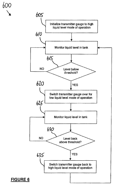
[0015] FIG. 6 illustrates a method of operating a fluid gauge in a
dual mode
for determination of both high and low fluid levels according to the
disclosure.
DETAILED DESCRIPTION OF EMBODIMENTS
[0016] Reference is initially made to FIG. 1, which illustrates an example
configuration of a system 10 for measuring fluid level according to the
disclosure.
As shown, system 10 may include at least one transmitter gauge 30 that is
operable, for example, with use of guided wave radar ("GWR") or the like to
measure fluid level of fluid housed within a tank. As described further below,
the
- 2 -
CA 02917266 2016-01-04
WO 2015/000068
PCT/CA2014/000557
GWR based measurement of fluid level may involve a time-of-flight
measurement(s)
or one or more electronic pulses transmitted down and reflected back up
transmitter
gauge 30. Fluid level information measured by the transmitter gauge 30 may be
transmitted to display unit 12, or to some other intermediate or other
processing
device, via a suitable communication channel 28, which may be any wired or
wireless communication channel such as a controller area network ("CAN") bus.
[0017] Display unit 12 may be any suitable configured device that
is
operative, in conjunction with hardware and/or driver circuitry, to display
one or
more different types of fluid level information. Thus, in some embodiments,
display
unity 12 may comprise multiple separate or otherwise distinct displays, such
as a
tank display 16 and/or a batch display 18. Display unit 12 may further
comprise
panel controls 20 for operating or controlling one or more different aspects
of
display 12. In some embodiments, display unit 12 may be connectable to
communication channel bus 28, so to provide communication between display unit
12 and one or more additional devices on communication channel 28, such as a
transmitter gauge 30, wireless transceiver 34, USB interface 36, and other
modules
38, which may be for example an in-cabin display/controller, high power
relays,
printers, printer interfaces, refractometer modules, a global positioning
system
("GPS") module, a temperature module, as well as others.
[0018] Display unit 12 may receive liquid level information from
transmitter
gauge 30 representing a measure level of a fluid housed within a tank in which
transmitter gauge 30 has been installed. By using depth charts specific to
such
tank, a suitably configured processor (or processors) within display unit 12
may
calculate a volume of the liquid within the tank for display on display unit
12. In the
embodiment shown in FIG. 1, display unit 12 features two distinct graphical
output
devices, i.e., tank display 16 and batch display 18.
[0019] In some cases, tank display 16 may be used to display a
volume of
liquid remaining within the tank, as calculated by the fluid level information
received
from transmitted gauge 30, while batch display 18 may be used to display some
other quantity, such as an amount of liquid that has been dispensed from the
tank.
Alternatively, tank and batch display 18 may each be used to display the
volume of
liquid remaining within two separate tanks, each such tank equipped with a
corresponding transmitter gauge 30. Thus, multiple different transmitter
gauges 30
are displayed in FIG. 1 connected to display unit 12 via communication channel
28.
- 3 -
CA 02917266 2016-01-04
WO 2015/000068
PCT/CA2014/000557
However, different numbers of transmitter gauges 30 (in general, one or more)
may
be included in system 10 in different embodiments. As explained further below,
the
liquid level information may be received at display unit 12 from a
refractometer
incorporated within or otherwise associated with a transmitter gauge 30.
[0020] In some embodiments, display unit 12 may be configured to receive
power, such as between 8 and 30 Volts DC (VDC) at up to 500 mA of current, via
a
power connection 22 included in display unit 12. One or more inputs 24 and/or
outputs 26, either analog and/or digital, may also be included in display unit
12.
Such inputs 24 may be connected to different components or other circuitry,
such as
temperature sensors, optical outputs, relay outputs, etc.
[0021] In some embodiments, system 10 may comprise one or both of a
wireless module 34 and a universal serial bus ("USB") module 36, as well as
other
modules 38, such as printers, high power relays, temperature sensors, pressure
transducers, or refractometer modules. In other embodiments, display unit 12
may
further comprise a built-in wireless transceiver module 14 configured for
communication over a suitable wireless communication protocol, such as WiFiO,
Bluetoothe, GPS or others. Wireless transceiver module 14 may be utilized, for
example, for non-contact programming of display unit 12, such as by wireless
uploading of software and/or firmware programs into persistent memory within
display unit 12 using a handheld programmer 40, or with personal computer
("PC")
42. Alternatively, such programming may be effected over communication channel
28 using USB module 36 as shown in FIG. 1.
[0022] In some embodiments, a data connection between PC 42 and
server
44, such as over the Internet or some other wide area communication protocol,
may
can be used to effect communication to one or both of display unit 12 and
transmitters 30 for different purposes, such as troubleshooting, remote
programming, software updates, etc.
[0023] In some embodiments, display unit 12 may include combinations
of
hardware and/or software and/or firmware components that are useful for
processing fluid level information received from transmitter gauge 30 via
communication channel 28. For example, the display unit 12 may include
firmware
that is operable to manage tables of data (or other suitable data structures)
for
maintaining transmitter gauge number(s), user input data, tank depth charts
and
alarm conditions. An analog to digital converter ("ADC") may be included in
display
- 4 -
CA 02917266 2016-01-04
WO 2015/000068
PCT/CA2014/000557
unit 12. When a pulse is launched down transmitter gauge 30, the interaction
of the
pulse with an air/fluid interface in a tank may generally produce a reflected
pulse
propagating back up the transmitter gauge 30, in addition to a partially
transmitted
pulse through the liquid. Such partially transmitted pulse may further
generate a
second reflected pulse propagating back up the transmitter gauge 30 upon
reaching
a termination of transmitter gauge 30. As used herein throughout, terms such
as
"air" or "air/fluid interface" may refer to any suitable gas or vapor, as well
as
mixtures thereof, which is housed in the tank together with a fluid. For
example, in
some embodiments, nitrogen gas can be used as a vapour blanket in a tank in
place of air.
[0024] In some embodiments, the ADC may be used in order to measure
one or more different time parameters of returning pulses on the transmitter
gauge
30. For example, returning reflected pulses may be expanded in time and the
result
sampled by ADC so as to determine time-of-flight on the transmitter gauge 30.
Alternatively, if an ADC with a sufficiently fast sampling rate is utilized,
then
expansion of returning pulses in time may not be required. The ADC may be
coupled to a processor and/or memory for storage or further data processing.
[0025] In some embodiments, display unit 12 may additionally, or
alternatively, comprise firmware that implements a pulse width modulation
("PWM")
module. In such cases, PWM module may be configured to generate a pulse having
a width that is proportional to the time-of-flight of a returning pulse on
transmitter
gauge 30.
[0026] Referring now to FIGS. 2A and 2B, two example embodiments of
a
transmitter gauge are shown. Each transmitter gauge shown may be operative to
generate electronic pulses that can be launched down the transmitter gauge
toward
a liquid housed in a tank in which the transmitter gauge may be installed, as
well as
to sense reflected pulses that have returned back up the transmitter gauge for
processing to determine time-of-flight or other useful parameters. The example
transmitter gauge 46 shown in FIG. 2A has a dual rod configuration, while the
example transmitter gauge 54 shown in FIG. 2B has a coaxial configuration.
[0027] Referring now to FIG. 2A specifically, an example
configuration of
dual rod transmitter gauge 46 is illustrated. As shown, transmitter gauge 46
may
comprise two rods, which may be substantially parallel to one another,
extending
downwardly from a transmitter coupler 47. Such parallel rods may comprise, for
- 5 -
CA 02917266 2016-01-04
WO 2015/000068
PCT/CA2014/000557
example, a signal rod 50 and a ground rod 48, each of which may terminate at a
shorting block 52 located at a distal end of transmitter gauge 46 relative to
transmitter coupler 47.
[0028] Referring now to FIG. 2B specifically, an example
configuration of
coaxial transmitter gauge 54 is illustrated. As shown, transmitter gauge 54
may
comprise an internal signal rod 58 that is supported within, and axially co-
located
with, a cylindrical ground conductor 56. Similar to dual rod transmitter gauge
46,
axial transmitter gauge 54 may include a transmitter coupler 55 and a shorting
block
60 located distally from transmitter coupler 55. Both internal signal rod 58
and
cylindrical grounder conductor 56 may extended between, e.g., downwardly,
transmitter coupler 55 and shorting block 60.
[0029] Either transmitter gauge 46 or transmitter gauge 54 may be
fixed at
least partially within a fluid tank oriented such that the transmitter coupler
47,55 is
above the shorting block 52,60, thereby extending downwardly into the fluid
tank so
as to be at least partially submerged within liquid housed within the tank.
Terms
such as "downward" or "downwardly", as used herein through, may (although not
necessarily) be used in reference to relative directional and/or spatial
orientations
without requirement of any absolute directions or orientations.
[0030] Thus, in some embodiments, one or more transmitter gauges 30
may
be fixed in place inside a tank or in an external stilling tube or well
attached to, and
in fluid communication with, the tank. Electronics inside transmitter gauge 30
may
be configured to generate electronic pulses, for example, short radar pulses
that are
transmitted down the transmitter gauge 30 on either signal rod 50 or 58, as
the case
may be, depending on the configuration of transmitter gauge 30. For example,
such
electronic pulses may have a pulse width of approximately 500 picoseconds.
When
an electronic pulse encounters an air-liquid interface or a shorting block 52,
60, the
impedance mismatch of the encountered discontinuity along the transmitter
gauge
causes a portion of the electronic pulse energy to be reflected back up the
transmitter gauge 30 for detection by a suitably configured sensor included in
30 transmitter gauge 30 (another portion of the electronic pulse energy is
transmitted
beyond the discontinuity). As an alternative to radar pulses, radio frequency
admittance, radio frequency capacitance and frequency modulated continuous
wave
may also be utilized in variant embodiments.
- 6 -
CA 02917266 2016-01-04
WO 2015/000068
PCT/CA2014/000557
[0031] The time-of-flight of one or more pulses transmitted along
the and
reflected back up the transmitter gauge 30 may be used to calculate the level
of the
liquid in the tank. For example, in some embodiments, system 10 may further
comprise a refractometer module configured to measure time-of-flight of
electronic
pulses along transmitter 30, which may be reflected from an air-liquid
interface or a
shorting block of transmitter 30, as well as other possible discontinuities
along
transmitter 30. Based on the measured times-of-flight and information relating
to the
geometry of the tank, the refractonneter module (or some other component
within
system 10 that has processing capability) may estimate the level and/or volume
of
fluid housed in the tank.
[0032] Referring now to FIGS. 3A and 3B, in some cases, the shape of
the
returning electronic pulses on the transmitter 30 may depend on the volume or
level
of liquid currently housed in the tank. For example, as shown in FIG. 3A, for
an air-
liquid interface 62 that is well above the shorting block 52,60 of transmitter
gauge
30, two distinct electronic pulses may be generated, including an electronic
pulse 64
generated by reflection at the air-liquid interface 62 and an electronic pulse
66
generated by reflection at the shorting block 52,60. At each encountered
discontinuity, the amount of electronic pulse energy transmitted and reflected
may
depend on one or more different properties, such as dielectric constant, of
the liquid
housed within the tank. Thus, as seen in FIG. 3A, the reflected pulse 64 may
generally exhibit a smaller amplitude and less dispersion than reflected pulse
66.
Because the air-liquid interface 62 is sufficiently far away from the shorting
block
52,60, the reflected pulses 64 and 66 are distinct, or substantially distinct,
from one
another and capable of separate detection.
[0033] However, in some cases, as seen in FIG. 3B, the air-liquid interface
62 may be close enough to the shorting block 52,60 that reflections due to the
air-
liquid interface 62 and shorting block 52,60 are mingled together and not
separately
detectable. In such cases, which for low liquid levels in the tank, only a
single
reflected pulse 68 may be generated due to reflections. Such occurrence may be
especially observed for liquids having a low dielectric constant, e.g., close
to that of
air, which therefore produce generally small reflections at air-liquid
interface 62 in
relation to the amount of electronic pulse energy transmitted through toward
shorting block 52,60. Thus, when the air-liquid interface 62 is close to
shorting block
62,60, the relatively small reflection at the air-liquid interface 62 may tend
to be co-
- 7 -
CA 02917266 2016-01-04
WO 2015/000068
PCT/CA2014/000557
mingled with the relatively large and dispersive reflection at the shorting
block
52,60.
[0034] According to the described embodiments, there are provided
methods for estimating the level or volume of fluid in a tank that are based
on
measured time-of-flight of electronic pulses in one of the plurality of
different
operating modes depending on the level of liquid in the tank. For example, in
a first
mode of operation corresponding to a first range of fluid levels at which an
air-
interface and shorting block of a fluid gauge transmitter generate distinct
reflections,
fluid or volume level may be estimated based on a time-of flight of a first
reflected
pulse from the air-fluid interface. However, in a second mode of operation
corresponding to a second range of fluid levels at which an air-interface and
shorting block of a fluid gauge transmitter do not generate distinct
reflections, fluid
or volume level may be estimated based on a time-of flight of a second
reflected
pulse from the shorting block. In such methods, the level of fluid in the tank
at which
reflections between indiscernible may be known in advance or otherwise
ascertained, and the appropriate mode of operation selected based on such
level.
These various modes of operations will be described below.
[0035] Referring now to FIG. 4, there is shown a method 400 of
determining
fluid level in a tank according to the disclosure. Method 400 may be performed
using a transmitter gauge, such as transmitter gauge 30, in some cases in
conjunction with additional electronic components or circuitry. While
illustrated in
FIG. 4 as a series of actions for convenience, method 400 may be modified in
one
or more ways without departing from the scope of the disclosure. For example,
additional actions not explicitly shown in FIG. 4 may be performed, while
those
actions shown may be varied.
[0036] In 405, one or more electronic pulses are generated, e.g., by
a
transmitter gauge 30 and transmitted down a probe or electrode of such
transmitter
gauge. As described herein, the electronic pulses may be guided wave radar
(GWR) pulses, or some alternative thereto, which are partially reflected back
up the
transmitter gauge upon encountering discontinuities, such as an air-liquid
interface
or shorting block.
[0037] In 410, a returning electronic pulse caused by reflection at
an air-
liquid interface is detected. As described herein, method 400 may be suitable
for
use in determining fluid and/or volume level of a liquid housed in a tank when
the
- 8 -
CA 02917266 2016-01-04
WO 2015/000068
PCT/CA2014/000557
level of such liquid is relatively high, such that reflected electronic pulses
from each
of an air-liquid interface and a terminal end, e.g., a shorting block, of a
transmitter
gauge are sufficiently distinct from each other. Thus, arrival of the
returning pulse
due to reflection at the air-liquid interface is detectable in 410
independently from a
returning pulse due to reflection at the shorting block, which may also be
detected.
[0038] In 415, liquid level within the tank is determined based on
the
measured time-of-flight of the reflected electronic pulse from the air-liquid
interface.
Provided the speed of the electronic pulse(s) on the transmitter gauge in air
are
known beforehand or are otherwise ascertainable, the distance travelled by the
reflected electronic pulse may be estimated from the measured time-of-flight
according to:
TOF = 2 liquid , (1)
you.
where 14,1õ,d represents the height of the air-liquid interface within the
tank, e.g.,
determined as a distance from a suitable reference point at the top of the
transmitter
gauge, vur represents the speed of the electronic pulse(s) in air, and TOF
represents
c
the measured time-of-flight of the returning pulse.
[0039] Referring now to FIG. 5, there is shown a method 500 of
determining
fluid level in a tank according to the disclosure. Method 500 may be performed
using a transmitter gauge, such as transmitter gauge 30, in some cases in
conjunction with additional electronic components or circuitry. While
illustrated in
FIG. 5 as a series of actions for convenience, method 500 may be modified in
one
or more ways without departing from the scope of the disclosure. For example,
additional actions not explicitly shown in FIG. 5 may be performed, while
those
actions shown may be varied.
[0040] In 505, one or more electronic pulses are generated, e.g., by a
transmitter gauge 30 and transmitted down a probe or electrode of such
transmitter
gauge. As described herein, the electronic pulses may be guided wave radar
(GWR) pulses, or some alternative thereto, which are partially reflected back
up the
transmitter gauge upon encountering discontinuities, such as an air-liquid
interface
or shorting block.
[0041] In 510, a returning electronic pulse caused by reflection at
a terminal
end, such as a shorting block, of a transmitter gauge is detected. As
described
- 9 -
CA 02917266 2016-01-04
WO 2015/000068
PCT/CA2014/000557
herein, method 500 may be suitable for use in determining fluid and/or volume
level
of a liquid housed in a tank when the level of such liquid is relatively low,
such that
reflected electronic pulses from the an air-liquid interface and terminal end
of a
transmitter gauge are comingled and therefore, effectively, indistinct from
each
other. In some cases, the contribution to the comingled pulse due to
reflection at the
shorting block may dominate in magnitude to the contribution due to reflection
at the
air-liquid interface. Thus, the arrival time of the single, comingled
reflection at the
top of the transmitter gauge may be taken as a reasonable estimate of the time-
of-
flight of the reflected pulse from the shorting block (as opposed to the
reflection
from the air-liquid interface).
[0042] In 515,
liquid level within the tank is determined based on the
measured time-of-flight of the reflected electronic pulse from the shorting
block.
Provided the speed of the electronic pulse(s) on the transmitter gauge in both
air
and the specific liquid being housed in the tank are known beforehand or are
otherwise ascertainable, the distance travelled by the reflected electronic
pulse may
be estimated from the measured time-of-flight according to:
TOF = 21
hliquid L gauge ¨ hliquid (2)
V
Vair liquid /
where Illiquid represents the height of the air-liquid interface within the
tank, e.g.,
determined as a distance from a suitable reference point at the top of the
transmitter
gauge, 1.,õõõ represents the known length of the transmitter gauge defined
between
such reference point and the shorting block, võ, represents the speed of the
electronic pulse(s) in air, viiquid represents the speed of the electronic
pulse(s) in the
housed liquid, and TOF represents the measured time-of-flight of the returning
pulse.
[0043] In equation (2)
above, liquid level within the tank may be determined
by measuring time-of-flight from a returning pulse reflected from the shorting
block
(as opposed to the air-liquid interface) because the speed response of such
electronic pulses in different liquid media is predictable. For example, such
speed
generally decreases relative to speed in air when a liquid is encountered, and
the
amount of the decrease is related to the dielectric constant of the liquid. By
knowing
the speed response of the electronic pulse, different times-of-flight of
returning
electronic pulse(s) may be correlated to the distance through which an
electronic
- 10-
CA 02917266 2016-01-04
WO 2015/000068 PCT/CA2014/000557
pulse travelled in liquid. Thus, by knowing the length of the transmitter
gauge, the
measured time-of-flight may also be correlated to an estimate of the height of
the
liquid within the tank.
[0044] In some embodiments,
the estimations of liquid level using time-of-
flight of an electronic pulse reflected from an air-liquid interface (e.g.,
method 400)
may tend to provide more accuracy than estimations using time-of-flight of
electronic pulses reflected from a shorting block of a transmitter gauge
(e.g.,
method 500). For example, as seen in FIGS. 3A and 3B, pulse dispersion in a
reflection 64 from the air-liquid interface is generally less than in a
reflection 66,68
from the shorting block. Thus, more accurate time-of-flight information may be
obtainable by sensing pulse 64, which leads to greater accuracy overall of
liquid
level estimation.
[0045] However, as described
herein, it may not be possible to detect usable
reflections 64 from the air-liquid interface 62 when the liquid level in the
tank is
sufficiently low that reflections 64 and 66 are superimposed into a single
composite
reflection 68. Thus, while it may generally be preferable to estimate liquid
level, if
possible, based on reflections 64 from the air-liquid interface 66 on account
of the
greater accuracy achievable, it may still be possible in such cases to
generate less
accurate determinations of liquid level based on reflections 68 from a
shorting block.
However, as will be appreciated, it would still also be possible to estimate
liquid level
based on reflections 66 from a shorting block, even in cases where reflections
64
are separately detectable.
[0046] Referring now to FIG.
6, there is illustrated a method 600 of
estimating liquid level in a tank using a transmitter gauge and/or transmitter
gauge
system that is capable of operation in a dual mode based on the liquid level
in
relation to a threshold value. As described herein, preference may be shown
for
liquid level estimation by detecting pulse reflections from an air-liquid
interface, as
opposed to a shorting block of a transmitter gauge so as to generate
relatively high
accuracy estimations if possible.
[0047] Thus, in 610,
a transmitter gauge or associated electronic
components or circuitry and/or processors are initialized for a high liquid
level mode
of operation. For example, such initialization may be performed at the time a
tank is
filled with a particular fluid or, alternatively, any time thereafter. As
described herein,
because fluid level may be more accurately measured when fluid levels are
high,
-11-
CA 02917266 2016-01-04
WO 2015/000068
PCT/CA2014/000557
e.g., above a minimum threshold level, preference may be given to operation in
the
high fluid level mode of operation. However, as described further below, fluid
level
may be monitored and operation of the transmitter gauge may be switched
between
high and low fluid level modes accordingly. Thus, in some cases,
initialization to a
high fluid level mode of operation may not be required or performed, in which
case
610 may be omitted.
[0048] In 610, liquid level in the tank may be monitored according
to the high
fluid level mode of operation. For example, as described herein, in such mode
of
operation, fluid level may be determined based on a measured time-of-flight of
returning pulses reflected from an air-liquid interface. Such fluid level
determinations
may be performed repeatedly, such as on regular (or irregular) intervals, as
well as
on request, so that liquid level in the tank may be tracked over time. In this
regard,
method 400 (shown in FIG. 4) may be utilized to estimate fluid levels.
[0049] In some embodiments, fluid level information generated by
transmitter gauge 30 may be transmitted to display unit 22 over communication
channel (shown in FIG. 1) for computation of fluid volume information that may
then
be displayed on the display unit 22. Alternatively, fluid volume information
may be
calculated internally to the transmitter gauge 30 and then transmitted over
communication channel 28 for display on display unit 22.
[0050] In some embodiments, so long as the monitored fluid level remains at
a relatively high level, which may be defined in terms of a minimum threshold
level,
transmitter gauge may be operated in the high fluid level mode of operation.
Thus,
in 615, the monitored fluid level may be compared to the minimum threshold
level,
which may be defined as a cut-off point between relatively "high" and "low"
fluid
levels, as these terms are used herein throughout. If the fluid level of the
tank has
not fallen below the minimum threshold level (indicating that fluid levels
remain
relatively high), then method 615 branches back to 610 wherein fluid level
continues
to be monitored according to the high fluid level mode of operation. However,
if it is
determined that fluid level in the tank has fallen below the minimum threshold
level,
then method 600 branches to 620 wherein operation of the transmitter gauge
switches over to the generally less accurate, low fluid level mode of
operation,
described further below.
[0051] Different approaches to determining in 615 whether fluid level
has
fallen below the minimum threshold level are possible. For example, as
described
- 12 -
CA 02917266 2016-01-04
WO 2015/000068
PCT/CA2014/000557
herein, such minimum threshold level may be related to the time separation
between returning pulses from the air-liquid interface and terminal end (e.g.,
shorting block) of the transmitter gauge, respectively. More specifically, the
minimum threshold level is at or near to the point wherein such pulses become
indistinguishable and not separately detectable.
[0052] In some embodiments, the minimum threshold level may be
determined ahead of time through, e.g., offline testing of a transmitter gauge
in
order to determine a level (or approximate range of levels) at which pulses
are no
longer separately detectable. Alternatively, to provide some buffer, the
minimum
threshold level may be determined as the level at which the time separation
between pulses returning from the air-liquid interface and the shorting block
drops
below a minimum detectable time in the refractometer module. In some cases,
the
minimum threshold level may be determined experimentally by detecting known
levels of fluid using the high level mode of operation and observing the point
at
which the generated estimates begin to deviate from the known actual values.
[0053] However the minimum threshold level is determined, it may be
stored
or programmed into the transmitter gauge for comparison against monitored
levels,
i.e., in 615, so that when the fluid level in the tank does drop below the
defined
minimum threshold level, the transmitter gauge may be switched over in 620 to
operation in the low fluid level mode of operation. For example, such switch
over
may involve transmitter gauge loading a different runtime program, or
executing
different control instructions stored in associated memory within the
transmitter
gauge, which are associated with the low fluid level mode of operation.
[0054] In 625, liquid level in the tank may be monitored according
to the low
fluid level mode of operation. For example, as described herein, in such mode
of
operation, fluid level may be determined based on a measured time-of-flight of
returning pulses reflected from a shorting block of the transmitter gauge,
together
with a known length of the transmitter gauge. Similar to 610, such fluid level
determinations in 625 may be performed repeatedly, such as on regular (or
irregular) intervals, as well as on request, so that liquid level in the tank
may be
tracked over time. In this regard, method 500 (shown in FIG. 5) may be
utilized to
estimate fluid levels.
[0055] Additionally, in some embodiments, fluid level information
generated
by transmitter gauge 30 in 625 may be transmitted to display unit 22 over
- 13 -
CA 02917266 2016-01-04
WO 2015/000068
PCT/CA2014/000557
communication channel for computation of fluid volume information that may
then
be displayed on the display unit 22. In other cases, fluid volume information
may be
calculated internally to the transmitter gauge 30 and then transmitted over
communication channel 28 for display on display unit 22.
[0056] In some embodiments, so long as the monitored fluid level remains at
a relatively low level, i.e., below the defined minimum threshold level,
transmitter
gauge may continue to be operated in the low fluid level mode of operation.
Thus, in
630, the monitored fluid level may be compared again to the minimum threshold
level. If the fluid level of the tank has not risen back above the minimum
threshold
level (indicating that fluid levels remain relatively low), then method 600
branches
back to 625 wherein fluid level continues to be monitored according to the low
fluid
level mode of operation. For example, fluid level may rise back above the
minimum
threshold level if additional fluid is added to the tank or if the fluid level
had been
improperly measured, which could occur if the fluid is not settled at the time
a
measurement is taken, or for any other reason.
[0057] However, if it is determined that fluid level in the tank has
risen back
above the minimum threshold level, then method 600 branches to 635 wherein
operation of the transmitter gauge switches back to the generally more
accurate,
high fluid level mode of operation. As above, switching to the high fluid
level mode
of operation may involve the transmitter gauge loading a different runtime
program,
or executing different control instructions stored in associated memory within
the
transmitter gauge, which are associated with the high fluid level mode of
operation.
Following switching to the high fluid level mode of operation in 635, method
600
may branch back to 610 wherein fluid level is monitored using the more
accurate
estimation based on time-of-flight of returning pulses from the air-liquid
interface.
[0058] While method 600 has been presented, for convenience and
clarity,
with a particular organization in which different actions occurs in an
illustrated
sequence, it will be appreciated that modifications and variations may be
possible.
For example, certain control or process flows in method 600 may be substituted
for
their functional equivalents. In other cases, different actions may be
performed in a
different sequence or not at all.
[0059] The above description has been provided with reference to
certain
example embodiments and is meant to be exemplary only. As such, one skilled in
the art may recognize that changes may be made to the embodiments described
- 14 -
CA 02917266 2016-01-04
WO 2015/000068
PCT/CA2014/000557
without departing from the scope of the invention disclosed. All such
modifications
and variations that will be apparent to those skilled in the art, in light of
a review of
this disclosure, are intended to be encompassed within the invention, which is
limited only by the appended claims.
- 15 -