Note: Descriptions are shown in the official language in which they were submitted.
CA 02917368 2016-01-12
LENGTH ADJUSTABLE WIRE ROPE RIGGING DEVICE AND LIFTING SYSTEM
EMPLOYING THE SAME
FIELD OF THE INVENTION
The present invention relates to wire rope rigging devices for lifting a load,
and more
particularly, to a length adjustable wire rope rigging device and lifting
system employing the
same.
BACKGROUND OF THE INVENTION
In present-day commercial and residential environments loads, and in
particular, heavy large size
loads such as, for example, air conditioner units, compressors, or modules of
gas/oil plants, are
lifted using a plurality of wire rope slings or chains connected to, for
example, lifting lugs of the
load and the hook of a crane. When lifting such, typically eccentric, loads,
it is highly important
to balance the same prior lifting. An unbalanced load exposes different wire
rope slings or chains
holding the same to different stresses which may result in failure of: one or
more of the wire rope
slings or chains; and/or the lifting lugs of the load having the wire rope
slings or chains
connected thereto, resulting in a catastrophic drop of the load.
Furthermore, when setting a load onto a foundation, anchor bolts, or other
securing devices it is
difficult, if not impossible, to properly place the load thereon when the same
is unbalanced.
Typically, loads are balanced by adding/removing shackles connected to the
wire rope sling or
chain, or by replacing the same with a wire rope sling or chain having a
different length. This is
usually determined in a time consuming trial and error process of slightly
lifting the eccentric
load and setting the same down again until the load is balanced properly.
It is desirable to provide a length adjustable wire rope rigging device that
enables remotely
controlled length adjustment thereof.
Page 1
CA 02917368 2016-01-12
It is also desirable to provide a length adjustable wire rope rigging device
that enables a
substantial change of length thereof.
It is also desirable to provide a length adjustable wire rope rigging device
that enables
measurement of a tension acting thereon.
It is also desirable to provide a lifting system comprising a plurality of
length adjustable wire
rope rigging devices that enables remotely controlled balancing of a load.
It is also desirable to provide an adjustable module lifting device comprising
a plurality of length
adjustable wire rope rigging devices that enables remotely controlled
balancing of the module.
SUMMARY OF THE INVENTION
Accordingly, one object of the present invention is to provide a length
adjustable wire rope
rigging device that enables remotely controlled length adjustment thereof
Another object of the present invention is to provide a length adjustable wire
rope rigging device
that enables a substantial change of length thereof
Another object of the present invention is to provide a length adjustable wire
rope rigging device
that enables measurement of a tension acting thereon.
Another object of the present invention is to provide a lifting system
comprising a plurality of
length adjustable wire rope rigging devices that enables remotely controlled
balancing of a load.
Another object of the present invention is to provide a length adjustable wire
rope rigging device
that enables measurement of a tension acting thereon.
According to one aspect of the present invention, there is provided a wire
rope device having
adjustable length between a first end and a second end thereof The wire rope
device comprises
Page 2
CA 02917368 2016-01-12
a first wire rope extending from the first end and a second wire rope
extending from the second
end. A length adjusting structure is disposed between the first end and the
second end. The length
adjusting structure has the first wire rope and the second wire rope connected
thereto. A support
strudture is disposed between the first end and the second end. The support
structure has the
length adjusting structure rotatable movable mounted thereto. A first guiding
structure and a
second guiding structure are disposed in the support structure for guiding the
first wire rope and
the second wire rope, respectively, such that when in operation a portion of
the first wire rope
extending from the first guiding element and a portion of the second wire rope
extending from
the second guiding element are disposed substantially along a same straight
line. A drive
mechanism is mounted to the support structure and connected to the length
adjusting structure for
adjusting the length of the wire rope device by rotatably moving the length
adjusting structure.
According to one aspect of the present invention, there is provided a wire
rope device having
adjustable length between a first end and a second end thereof. The wire rope
device comprises
a first wire rope extending from the first end and a second wire rope
extending from the second
end. A length adjusting structure is disposed between the first end and the
second end. The length
adjusting structure has the first wire rope and the second wire rope connected
thereto. A support
structure is disposed between the first end and the second end. The support
structure has the
length adjusting structure rotatable movable mounted thereto. A first guiding
structure and a
second guiding structure are disposed in the support structure for guiding the
first wire rope and
the second wire rope, respectively, such that when in operation a portion of
the first wire rope
extending from the first guiding element and a portion of the second wire rope
extending from
the second guiding element are disposed substantially along a same straight
line. A drive
mechanism is mounted to the support structure and connected to the length
adjusting structure for
adjusting the length of the wire rope device by rotatably moving the length
adjusting structure.
The length adjusting structure comprises a plurality of clamping devices
connecting the length
adjusting structure to the first and the second wire rope. The clamping
devices are operable in an
open mode for receiving/releasing the respective wire rope and in a closed
mode for clamping the
respective wire rope. The support structure comprises a third guiding
structure and a fourth
guiding structure disposed in proximity to the second guiding structure and
the first guiding
structure, respectively, the third guiding structure and the fourth guiding
structure for guiding the
Page 3
CA 02917368 2016-01-12
first wire rope and the second wire rope, respectively, such that when in
operation a portion of
the first wire rope and a portion of the second wire rope exit/enter the
support structure
substantially parallel to the straight line.
According another aspect of the present invention, there is provided a system
for lifting a load.
The system comprises a plurality of wire rope devices. Each wire rope device
has a controllable
drive mechanism for adjusting a length between a first eye and a second eye
thereof. A controller
is in communication with the controllable drive mechanism of each of the wire
rope devices for
controllably adjusting the length of each of the wire rope devices.
According another aspect of the present invention, there is provided a module
lifting device. The
module lifting device comprises a spreader bar having a rail system disposed
thereon along a
longitudinal axis thereof. A plurality of load holding bars is disposed along
the spreader bar.
Each load holding bar is movable mounted to the rail system and oriented
substantially
perpendicular to spreader bar. A controllable load holding bar drive mechanism
is mounted to
each load holding bar for controllably moving the load holding bar along the
spreader bar. A wire
rope device having a controllable drive mechanism for adjusting a length
thereof is connected to
each end of each load holding bar.
The advantage of the present invention is that it provides a length adjustable
wire rope rigging
device that enables remotely controlled length adjustment thereof.
A further advantage of the present invention is that it provides a length
adjustable wire rope
rigging device that enables a substantial change of length thereof.
A further advantage of the present invention is that it provides a length
adjustable wire rope
rigging device that enables measurement of a tension acting thereon.
A further advantage of the present invention is that it provides a lifting
system comprising a
plurality of length adjustable wire rope rigging devices that enables remotely
controlled
balancing of a load.
Page 4
CA 02917368 2016-01-12
A further advantage of the present invention is that it provides an adjustable
module lifting
device comprising a plurality of length adjustable wire rope rigging devices
that enables remotely
controlled balancing of the module.
BRIEF DESCRIPTION OF THE DRAWINGS
A preferred embodiment of the present invention is described below with
reference to the
accompanying drawings, in which:
Figures la and lb are simplified block diagrams illustrating in a top view and
a side view,
respectively, a length adjustable wire rope device according to a preferred
embodiment of
the invention;
Figures lc to le are simplified block diagrams illustrating in two side views
and a
perspective view, respectively, a central portion of the length adjustable
wire rope device
according to a preferred embodiment of the invention;
Figures if and lg are simplified block diagrams illustrating in top views the
length
adjustable wire rope device according to a preferred embodiment of the
invention with
the device being in the retracted position and the extended position,
respectively;
Figures 1 h and li are simplified block diagrams illustrating in a top view
and a side view,
respectively, a length adjusting structure of the length adjustable wire rope
device
according to a preferred embodiment of the invention;
Figures I j and lk are simplified block diagrams illustrating in a top view
and a side view,
respectively, a housing enclosing the length adjusting structure of the length
adjustable
wire rope device according to a preferred embodiment of the invention;
Figure 11 is a simplified block diagram illustrating in a perspective view the
length
Page 5
CA 02917368 2016-01-12
adjusting structure of the length adjustable wire rope device according to a
preferred
embodiment of the invention;
Figures lm to lp are simplified block diagrams illustrating in a perspective
view, a top
view, a side view, and a cross sectional view, respectively, a clamping device
of the
length adjustable wire rope device according to a preferred embodiment of the
invention;
Figures lq and lr are simplified block diagrams illustrating in a perspective
view and a
side view, respectively, a collect of the clamping device of the length
adjustable wire rope
device according to a preferred embodiment of the invention;
Figures 2a to 2d are simplified block diagrams illustrating in an exploded
perspective
view, a side view, and the cross sectional views, respectively, a planetary
gear of the
length adjustable wire rope device according to a preferred embodiment of the
invention;
Figure 3a is a simplified block diagram illustrating in a side view a collect
having a strain
gauge of the clamping device of the length adjustable wire rope device
according to a
preferred embodiment of the invention;
Figure 3b is a simplified block diagram illustrating in a perspective view a
load
measuring control circuit of the length adjustable wire rope device according
to a
preferred embodiment of the invention;
Figures 3c to 3e are simplified block diagrams illustrating a control system
of the length
adjustable wire rope device according to a preferred embodiment of the
invention;
Figures 4a and 4b are simplified block diagrams illustrating determination of
center of
gravity of a load using the length adjustable wire rope device according to a
preferred
embodiment of the invention;
Figures 5a and 5b are simplified block diagrams illustrating rotation of a
load using the
Page 6
CA 02917368 2016-01-12
length adjustable wire rope device according to a preferred embodiment of the
invention;
Figures 6a to 6d are simplified block diagrams illustrating in a perspective
view, a top
' view, a front view, and a side view, respectively, a module
lifting device according to a
preferred embodiment of the invention employing the length adjustable wire
rope device;
Figure 6e is a simplified block diagram illustrating in a side view a load
holding bar of
the module lifting device according to a preferred embodiment of the invention
employing the length adjustable wire rope device;
Figure 6f is a simplified block diagram illustrating in a cross sectional view
a spreader bar
of the module lifting device according to a preferred embodiment of the
invention
employing the length adjustable wire rope device;
Figure 6g is a simplified block diagram illustrating in a perspective view a
section of the
spreader bar having the load holding bar mounted thereto of the module lifting
device
according to a preferred embodiment of the invention employing the length
adjustable
wire rope device;
Figures 6h and 6i are simplified block diagram illustrating in cross sectional
the load
holding bar mounted to the spreader bar of the module lifting device according
to a
preferred embodiment of the invention employing the length adjustable wire
rope device;
Figure 6j is a simplified block diagram illustrating in a cross sectional view
a detail of the
drive mechanism of the load holding bar of the module lifting device according
to a
preferred embodiment of the invention employing the length adjustable wire
rope device;
Figures 6k and 61 are simplified block diagrams illustrating in cross
sectional views
details of the load holding bar mounted to the spreader bar of the module
lifting device
according to a preferred embodiment of the invention employing the length
adjustable
wire rope device; and,
Page 7
CA 02917368 2016-01-12
Figures 6m and 6n are simplified block diagrams illustrating in perspective
views a
coupling mechanism for connecting sections of the spreader bar of the module
lifting
device according to a preferred embodiment of the invention employing the
length
adjustable wire rope device.
DESCRIPTION OF THE PREFERRED EMBODIMENT
Unless defined otherwise, all technical and scientific terms used herein have
the same meaning as
commonly understood by one of ordinary skill in the art to which the invention
belongs.
Although any methods and materials similar or equivalent to those described
herein can be used
in the practice or testing of the present invention, the preferred methods and
materials are now
described.
While the description of the preferred embodiments hereinbelow is with
reference to a length
adjustable wire rope device used for rigging a load to a lifting device such
as, for example, the
hook of a crane, it will become evident to those skilled in the art that the
embodiments of the
invention are not limited thereto, but that the length adjustable wire rope
device is also
implementable as adjustable cable tensioners of, for example, guy-wires of
masts or suspension
cables of suspended roof structures.
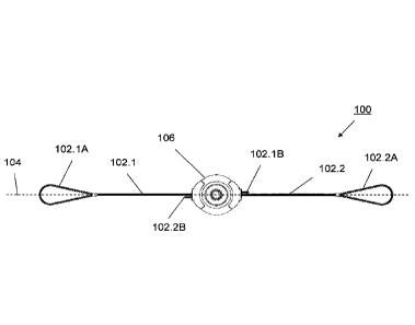
Referring to Figures la to 1r, a length adjustable wire rope device 100
according to a preferred
embodiment of the invention is provided. The length adjustable wire rope
device 100 comprises
a first wire rope 102.1 extending from a first end 102.1A and a second wire
rope 102.2 extending
from a second end 102.2A. The wire rope ends 102.1A, 102.2A forming, for
example, eyes of a
wire rope sling ¨ as illustrated in Figure la - for use in crane rigging. A
length adjusting structure
118 is disposed between the first end 102.1A and the second end 102.2A. The
length adjusting
structure 118, 120 has the first wire rope 102.1and the second wire rope 102.2
connected thereto.
The length adjusting structure 118 is rotatable movable mounted to a support
structure which is,
preferably, provided as an enclosing housing 106. Guiding structures 124.1 and
124.3 are
disposed in the housing 106 in proximity to wire rope openings 126.1 and
126.3, respectively, for
Page 8
CA 02917368 2016-01-12
guiding the first wire rope 102.1 and the second wire rope 102.2,
respectively, such that when in
operation a portion of the first wire rope 102.1 extending from the guiding
element 124.1 and a
portion of the second wire rope 102.2 extending from the guiding element 124.3
are disposed
substantially along a same straight line 104. A drive mechanism is mounted to
the housing 106
and connected to the length adjusting structure 118 for adjusting the length
of the wire rope
device 100 by rotatably moving the length adjusting structure 118 about axis
116 which is
oriented substantially perpendicular to the line 104.
Preferably, the drive mechanism comprises a planetary gear 108.1, 108.2,
108.3, as will be
described hereinbelow with reference to Figures 2a to 2d, and electric motor
110. Further
preferably, the electric motor 110 is powered using rechargeable battery 112
mounted to the
electric motor 110, as illustrated in Figure lc or, alternatively, to the
housing 106 opposite to the
drive mechanism for balancing the weight. Operation of the electric motor 110
is controlled via
controller 114, preferably, mounted thereto. The drive mechanism is removable
mounted to the
housing 106 in a conventional manner using, for example, screw bolts, and is
connected to the
length adjusting structure 118 also in a conventional manner using for
example, mating coupler
elements 128 and 130. Alternatively, a hydraulic or pneumatic drive may be
employed.
Preferably, the length adjusting structure 118 is provided as a wheel 118
having a wire rope
interacting structure disposed on its circumference - for example, in the form
of a channel having
a substantially semi-circular cross section - for accommodating a portion of
the first wire rope
102.1 and the second wire rope 102.2 therein. The hub of the wheel 118 is
shaped to form the
coupler element 128 for being mated with the respective coupler element 130 of
the planetary
gear 108.1, 108.2, 108.3. For example, the wheel 118 is made of steel using a
conventional
forging or molding process and is rotatable movable mounted to the housing 106
in a
conventional manner using, for example, ball bearings 122.
The housing 106 further comprises guiding structures 124.2 and 124.4 disposed
in proximity to
wire rope openings 126.2 and 126.4, respectively, which are placed adjacent
the wire rope
openings 126.3 and 126.1, respectively, as illustrated in Figures 1 h and 1j.
The guiding structures
124.2 and 124.4 guide the first wire rope 102.1 and the second wire rope
102.2, respectively,
Page 9
CA 02917368 2016-01-12
such that when in operation a portion of the first wire rope 102.1 and a
portion of the second wire
rope 102.1 exit/enter the housing 106 substantially parallel to the straight
line. The guiding
structures 124.1 to 124.4 are, for example, provided as channels disposed in
the housing 106
having a substantially semi-circular cross section for accommodating a portion
of the respective
wire rope therein.
Clamping devices 120 are mounted to the wheel 118 in a conventional manner
using, for
example, screw fasteners. The clamping devices 120 are operable in an open
mode for
receiving/releasing the respective wire rope 102.1, 102.2 and in a closed mode
for clamping the
respective wire rope 102.1, 102.2, as illustrated in Figure 11. Preferably,
six clamping devices
120 are provided for safety reasons such that each wire rope 102.1, 102.2 is
always clamped by
two clamping devices 120 in the closed mode while a third clamping device 120
is in the open
mode for receiving/releasing the respective wire rope 102.1, 102.2.
The inside of the housing 106 is shaped such that it comprises: sections 106A
forming a channel
having a circular cross section for accommodating the clamping devices 120 in
the closed mode
therein when rotated about the axis 116; enlarged sections 106B disposed in
proximity to the
openings 126.1 to 126.4 for enabling movement of the clamping devices 120 in
the open mode
therethrough with the cross section of the enlarged sections 106B gradually
changing to the
circular cross section of the sections 106A for enabling gradual
opening/closing of the clamping
devices 120, as illustrated in Figures lh to 11. For example, the housing 106
is made of steel
using a conventional forging or molding process for forming two portions of
the housing 106 by
splitting the same in a plane through line 104 and oriented perpendicular to
the axis 116, which
are mounted together in a conventional manner using screw fasteners.
In operation, the length of the wire rope device 100 is extended by rotating
the wheel 118 with
the clamping devices 120 in counter clockwise direction, as illustrated by the
block arrows in
Figure if. During the rotation of the wheel two clamping devices 120 in the
closed position move
the respective wire rope while the third clamping device 120 - in proximity to
the openings 126.1
to 126.4 - first releases one of the wire ropes and then receives the other of
the wire ropes, as
illustrated in Figures 1 h and li. This process may be continued¨with the
wheel 118 being
Page 10
CA 02917368 2016-01-12
rotated 3600 several times - until the length of the wire rope device 100 is
properly adjusted or
fully extended, as illustrated in Figure lg, thus enabling a substantial
change of length of the wire
. rope device 100. Preferably, the wire ropes 102.1, 102.2 are provided with
stopping elements
102.1B, 102.2B, respectively, which are abutted at the respective openings
126.2, 126.4 when the
wire rope device 100 is fully extended to prevent accidental release of the
wire ropes 102.1,
102.2 from the wheel 118. The wire rope device 100 is shortened by performing
the same process
with the wheel 118 being rotated in clockwise direction.
Referring to Figures lm to 1r, each clamping device 120 comprises a cup
structure having a fixed
cup portion 120A and a movable cup portion 120B. The fixed cup portion 120A is
connected to
mounting plates 120E. The movable cup portion 120B is pivotally movable
mounted to the fixed
cup portion 120A at hinge 120C. The fixed cup portion 120A and the movable cup
portion 120B
form in the closed position a tapered bore for accommodating collets 120F
therein ¨ for example,
three collets 120F.1, 120F.2, and 120F.3. Each of the collets 120F is movable
along a direction
parallel to the wall of the tapered bore guided by guiding element 120H which
is accommodated
in a respective channel 120G disposed in the cup structure. Each of the
collets 120F is spring
loaded via compression spring 1201 disposed between the cup structure and the
guiding element
120H. Preferably, the outside of the movable cup portion 120B comprises ball
bearings 120D for
interacting with the inside wall of the housing 106, thus facilitating
movement of the movable
cup portion 120B therealong.
The cup structure is made, for example, in two pieces ¨ cup portion 120A with
mounting plates
120E and movable cup portions 120B - of steel using a conventional forging or
molding process.
The two pieces are then pivotally movable connected using, for example, a
barrel hinge
mechanism.
As the cup is closed after receiving the wire rope 102.1, 102.2, gripping
surfaces 120J, for
example, as illustrated in Figure 1r, of the collets 120F grip the wire rope,
and as the cup
structure is moved, the collets 120F are moved towards the tapered end of the
bore and pressed
between the wall of the bore and the wire rope resulting in a non-fail slip
connection. For
releasing the wire rope 102.1, 102.2 the compression springs 1201¨which have
been compressed
Page 11
CA 02917368 2016-01-12
during the previous gripping process of the wire rope 102.1, 102.2 ¨ push the
collets 120F away
from the tapered end resulting in the opening of the cup structure.
It is noted that wire rope device 100 employing the cup structure described
hereinabove is
adaptable for various sizes of wire ropes having, for example, a diameter
ranging between 2cm
and 15cm.
Alternatively, the wire ropes may be fixedly mounted to the length adjusting
structure comprising
a wheel or winch drum, for example, in situations where only wire ropes of
small cross sections ¨
for example, wire ropes having less than 2cm diameter - are employed or where
only small length
adjustments ¨ requiring less than 180 degree rotation - are needed.
Referring to Figures 2a to 2d, the drive mechanism, preferably, comprises a
triple compound
planetary gear 108.1, 108.2, 108.3 having a gear ratio of, for example,
1800:1, enabling use of a
Shp motor to achieve 43000Nm torque for rotating the wheel 118. The three gear
sections 108.1,
108.2, 108.3 are of similar conventional planetary gear design and comprise
the same
components as illustrated in Figure 2d for gear section 108.3, which comprises
annular gear
108.3A (fixedly mounted to the gear housing), planet gears 108.3C rotatable
movable mounted to
carrier 108.3B, and sun gear 108.3D. The carrier 108.3B is driven by the motor
110 via coupler
136, thus rotating the carrier 108.3B with the planetary gears 108.3C which in
concert with the
annular gear 108.4 drive the sun gear 108.3D. The sun gear 108.3 is connected
to the carrier gear
of gear section 108.2 via coupler 134 while the sun gear of gear section 108.2
is connected to the
carrier gear of gear section 108.1 via coupler 132. Finally the sun gear of
gear section 108.1 is
connected to coupler element 130 for being mated with coupler element 128 of
the wheel 118.
Each gear section reduces the rotational speed provided by the motor 110, thus
increasing the
torque.
Preferably, each gear section 108.1, 108.2, 108.3 is provided as a separate
unit disposed in a
respective gear housing 109.1, 109.2, 109.3, as illustrated in Figure 2c, for
facilitating
assembly/disassembly of the wire rope device 100. The gear housings 109.1,
109.2, 109.3 are
then connected in a conventional manner using, for example, screw bolts, while
the couplers 136,
Page 12
CA 02917368 2016-01-12
134, and 132 comprise mating coupler elements, for example, similar to the
mating coupler
elements 128 and 130.
The gear components are made of, for example, steel using a conventional
forging or molding
process, while the gear housings are made of, for example, a light weight
material such as
aluminum using a conventional forging or molding process, for facilitating
handling of the gear
sections. Alternatively, some gear components, for example, of gear section
108.3 may also be
made of a light weight material.
Preferably, the drive mechanism comprises a conventional hoist load brake
mechanism such as,
for example, a sprag clutch, to prevent the wire rope device 100 from dropping
the load in the
event of a mechanical/electrical failure of thereof.
Alternatively, the drive mechanism may comprise different types of gear such
as, for example, a
double compound planetary gear, a single planetary gear, or a worm drive. It
is noted that it has
been found that the triple compound planetary gear with each gear section in a
separate gear
housing, as described hereinabove, substantially facilitates handling during
assembly/disassembly of the device.
Referring to Figures 3a to 3e, a load lifting system 200 according to a
preferred embodiment of
the invention is provided. Preferably, each clamping device 120 of the wire
rope device 100 is
provided with a conventional strain gauge 202 disposed on at least one of its
collets 120F for
measuring the strain acting thereon induced by the load acting on the wire
rope device 100, as
indicated by the block arrow in figure 3a. For example, each clamping device
120 disposed on
the wheel 118 is provided with one strain gauge 202.1, ... 202.6 with each
being connected to a
respective conventional Wheatstone bridge 210.1, ... 210.6 ¨ for example, a
full Wheatstone
bridge for measuring the change of resistance of the strain gauge caused by
the strain acting on
the collet 120F - of control circuit 204 disposed on the wheel 118, as
illustrated in Figures 3b and
3c. The control circuit 204 further comprises a processor 212 such as, for
example, an off-the-
shelf Programmable Logic Controller (PLC) for executing executable commands
stored in non-
volatile memory 214 such as, for example, flash-memory, with the processor 212
being
Page 13
CA 02917368 2016-01-12
connected to each of the Wheatstone bridges 210.1 to 210.6. The processor 212
determines the
load based on the measurements received from each of the Wheatstone bridges
210.1 to 210.6
and provides load data indicative of the load acting on the wire rope device
100 to antenna 216
connected thereto for wireless transmission. The controller 204 and the strain
gauges 202 are
powered, for example, using a rechargeable battery disposed in the wheel 118.
Preferably, the
load data are transmitted to the control circuit 114 disposed on the motor 110
where they are
received by antenna 226, illustrated in Figure 3d. The control circuit 114
comprises a processor
220 such as, for example, an off-the-shelf Programmable Logic Controller (PLC)
for executing
executable commands stored in non-volatile memory 222 such as, for example,
flash-memory,
with the processor 220 being connected to the antenna 226, antenna 224, the
memory 222, the
electric motor 110 and the battery 112. Preferably, the control circuit 114
communicates remotely
with computer 230 via the antenna 224, using state of the art wireless
telecommunication
technologies such as, for example, cell phone network technologies or Wi-Fi
local network
technologies.
The computer 230 such as, for example, a laptop computer or smartphone, in
wireless
communication with the controller 114 of each of a plurality of wire rope
devices 100.1, 100.2,
... enables the operator to control the length adjustment of a plurality of
wire rope devices 100.1,
100.2, ..., employed for lifting a load, as illustrated in Figure 3e. For
example, the operator
manually adjusts each of the wire rope devices based on the load data received
from the wire
rope devices such that the wire rope devices are exposed to a same load.
Alternatively, the
computer is programmed to determine the necessary adjustments and
automatically controls the
adjustment of each of the wire rope devices 100. Preferably, the controller
114 of each of the
wire rope devices has a unique ID which is transmitted to the computer 230 for
identification and
enabling the operator to identify the location where each of the wire rope
devices 100 is
connected to the load.
Figures 4a and 4b, illustrate the determination of the center of gravity of a
load 10 using 4 wire
rope devices 100.1, 100.2, 100.3, 100.4 connected at respective points 1, 2,
3, 4 to the load 10
and to a lifting device such as the hook 12 of a crane. When the load is fully
suspended and
stationary, the load acting on each of the wire rope devices is measured ¨
preferably, a plurality
Page 14
CA 02917368 2016-01-12
of times and averaged. For example, the average load for each point (wire rope
device 100) is:
Point 1: 5,537kg;
, Point 2: 3,053kg;
Point 3: 2,330kg; and,
Point 4: 2,107kg.
Adding the loads acting at the 4 points provides the average total weight of
the load 10 of
13,027kg. Knowing the distances between the 4 points enables the determination
of the center of
gravity 11 of the load 10, as illustrated in Figure 4b.
Optionally, the computer 230 transmits data indicative of the average total
weight of the load 10
and the center of gravity 11 of the load 10 to a database of the client and/or
the crane operator
using cell phone communication.
Preferably, if during lifting the controller 114 of the wire rope device 100
determines a load
exceeding the capacity of the same, the controller 114 shuts down the
operation thereof to
prevent overload.
Load testing of wire rope devices is required every year for safety. The
unique identification of
each of the wire rope devices 100 as described hereinabove enables logging of
the load testing in
the memory 222 of each wire rope device 100 or, alternatively, in a central
database for tracking
the load testing of a plurality of wire rope devices 100. For example, when
the wire rope device
100 is in use the operator is provided with a warning message if the one year
period from the last
load test has elapsed or the expiration date thereof is within a predetermined
time interval such
as, for example, 1 month.
Optionally, the controller 114 monitors the battery 112 and provides a warning
message when
battery capacity is low.
Further optionally, the controller 114 determines the length of extension of
the wire ropes 102. 1
and 102.2 and shuts down the operation of the wire rope device 100 to prevent
the same from
being extended/retracted too far.
Page 15
CA 02917368 2016-01-12
Further optionally, the wire rope device 100 comprises temperature sensors
connected to the
controller 114 for sensing the temperature of the planetary gear 108 and the
electric motor 110. In
case'a predetermined temperature limit is reached, the controller shuts down
the operation of the
wire rope device 100 to prevent overheating and sends a warning message to the
operator
indicating the same.
Further optionally, the controller 114 tracks the duty cycle, i.e. the hours
of operation, of the wire
rope device 100 and provides a warning message if the predetermined time limit
of the duty cycle
such as, for example, 20,000hrs has elapsed or the expiration thereof is
within a predetermined
time interval such as, for example, 100hrs.
Referring to Figures 5a and 5b, an application of the wire rope devices 100
for rotating a load 10
from horizontal to vertical is illustrated. An elongated loads such as, for
example, a wind turbine
tower, is transported oriented horizontal and rotated into a vertical
orientation for placing the
same on its foundation. Typically, such loads are rotated using two cranes, a
first (lifting) crane
for raising the top end of the tower and a second (tailing) crane for lowering
the bottom end of
the tower. Using wire rope devices 100, a single crane is sufficient to
perform this operation.
Wire rope devices 100.T are connected to the top end 10T of the load 10 and
hook 12, while wire
rope devices 100.B are connected to the bottom end 10B of the load 10 and the
same hook 12. By
shortening the wire rope devices 100.T and lengthening the wire rope devices
100.B, as indicated
by the block arrows in Figures 5a and 5b, the load 10 is rotated such that the
top end 10T of the
load 10 is raised and the bottom end 10B of the load 10 is lowered. This
process is continued
until the load 10 is oriented vertical.
Referring to Figures 6a to 6n, a module lifting device 300 according to a
preferred embodiment
of the invention is provided. The module lifting device 300 comprises a
spreader bar 302 which
is, preferably, connected via lift lugs 302G to a lifting device 12 using a
plurality of wire rope
devices 100. The spreader bar 302 has a rail system 302B, 302C disposed
thereon along a
longitudinal axis 301 thereof. A plurality of load holding bars 304 are
movable mounted to the
rail system 302B, 302C and oriented substantially perpendicular to spreader
bar 302. A
Page 16
CA 02917368 2016-01-12
controllable load holding bar drive mechanism 304E is mounted to each load
holding bar 304 for
controllably moving the load holding bar 304 along the spreader bar 302. A
wire rope device 100
. is connected to a respective connecting element 304C disposed at each
end of each load holding
bar 304. A bottom end of each wire rope device 100 is connected to lift lugs
of the module 10 or
a module supporting bar 306 having the module 10 placed thereon.
Preferably, each load holding bar 304 comprises sliding rails 304B to
accommodate different
widths of the modules, as illustrated in Figure 3e.
The load holding bars 304 are movable mounted to the spreader bar 302 via
support structure
304D comprising linear roller bearings 304H interacting with rails 302B and
roller alignment
bearings 304G interacting with rails 302C, as illustrated in Figures 6k and
61. The load holding
bars 304 are moved using a drive sprocket wheel 304F interacting with a linear
drive gear 302D
disposed on the spreader bar 302 along the longitudinal axis 301, as
illustrated in Figures 6f and
6j. Preferably, the same remotely controlled drive mechanism as in the wire
rope device 100 is
employed in the drive 304E.
Preferably, the spreader bar 302 is of tubular 304A design having rib supports
3021 mounted
thereto along the longitudinal axis 301, for example, every 50cm.
Optionally, the ends of the spreader bar 302 comprise support legs 302H
mounted thereto to keep
the spreader bar 302 erect for rigging and above ground.
Preferably, the spreader bar 302 is length adjustable by connecting respective
mating end
portions 302E, 302F of a plurality of spreader bar sections 302.1, 302.2, ...,
as illustrated in
Figure 6m, with each spreader bar section having a lift lug 302G.
Further preferably, the spreader bar sections are connected using an automated
locking device
comprising guide locks 302J and spring loaded pins 302K, as illustrated in
Figure 6n. The
spreader bar sections are connected by sliding end portion 302E into end
portion 302F. Once the
guide locks 302J come in contact with the pins 302K the pins 302K rise and
allow the guide
Page 17
CA 02917368 2016-01-12
locks 302J to pass through. Once in place the springs force the pins 302K back
to their original
location and lock the guide locks 302J.
ReMotely controlled lengthening/shortening of the wire rope devices 100 of the
module lifting
device 300, as well as movement of the load holding bars 304 along the
spreader bar 302, enables
balancing of the module 10.
The present invention has been described herein with regard to preferred
embodiments. However,
it will be obvious to persons skilled in the art that a number of variations
and modifications can
be made without departing from the scope of the invention as described herein.
Page 18