Language selection

Search

Patent 2917406 Summary

Third-party information liability

Some of the information on this Web page has been provided by external sources. The Government of Canada is not responsible for the accuracy, reliability or currency of the information supplied by external sources. Users wishing to rely upon this information should consult directly with the source of the information. Content provided by external sources is not subject to official languages, privacy and accessibility requirements.

Claims and Abstract availability

Any discrepancies in the text and image of the Claims and Abstract are due to differing posting times. Text of the Claims and Abstract are posted:

  • At the time the application is open to public inspection;
  • At the time of issue of the patent (grant).
(12) Patent: (11) CA 2917406
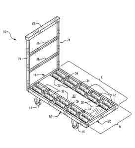
(54) English Title: STAGING CART FOR TRANSPORTING MATTRESSES
(54) French Title: CHARIOT SERVANT AU TRANSPORT DE MATELAS
Status: Granted
Bibliographic Data
(51) International Patent Classification (IPC):
  • B62B 3/04 (2006.01)
  • B62B 3/00 (2006.01)
  • B62B 5/06 (2006.01)
(72) Inventors :
  • JAN, FRANCIS G. (United States of America)
(73) Owners :
  • DREAMWELL, LTD. (United States of America)
(71) Applicants :
  • DREAMWELL, LTD. (United States of America)
(74) Agent: NORTON ROSE FULBRIGHT CANADA LLP/S.E.N.C.R.L., S.R.L.
(74) Associate agent:
(45) Issued: 2023-05-09
(22) Filed Date: 2016-01-12
(41) Open to Public Inspection: 2016-07-23
Examination requested: 2020-12-14
Availability of licence: N/A
(25) Language of filing: English

Patent Cooperation Treaty (PCT): No

(30) Application Priority Data:
Application No. Country/Territory Date
62/106,953 United States of America 2015-01-23

Abstracts

English Abstract

A staging cart for moving multiple packaged mattresses generally includes a base frame having a length and a width dimension; a handle frame extending upwardly from a rear end of the cart; a pair of rear wheels and a pair of forward wheels mounted to a bottom surface of the base frame at the rear and forward ends of the base frame, respectively; a platform portion coupled to the base frame spanning a length of the base frame and having a planar surface, wherein the platform portion has a width dimension less than the width dimension of the base frame and is medially located within the base frame; and at least one roller coupled to the base frame spanning the length dimension and adjacent to at least one side of the platform portion, wherein the at least one has an axis of rotation parallel to the longitudinal axis of the platform portion.


French Abstract

Il est décrit un chariot intermédiaire pour déplacer plusieurs matelas emballés qui comprend essentiellement un bâti de base présentant des dimensions applicables à la longueur et à la largeur; un support de poignée sétendant vers le haut à partir dune extrémité arrière du chariot; une paire de roues arrière et une paire de roues avant montées sur une surface inférieure du bâti de base aux extrémités arrière et avant du bâti de base, respectivement; une partie plate-forme raccordée au bâti de base sétendant sur une longueur du bâti de base et comprenant une surface planaire, dans laquelle la partie plate-forme a une dimension en largeur inférieure à la dimension en largeur du bâti de base et est située dans la partie médiane à lintérieur du bâti de base; et au moins un rouleau raccordé au bâti de base sétendant sur la dimension en longueur et adjacent à au moins un côté de la partie plate-forme, dans lequel au moins un côté a un axe de rotation parallèle à laxe longitudinal de la partie de plate-forme.

Claims

Note: Claims are shown in the official language in which they were submitted.

CLAIMS
What is claimed is:
1. A cart for transporting packaged mattresses, the cart comprising:
a base frame having a length and a width dimension;
a handle frame extending upwardly from a rear end of the base frame;
a pair of rear wheels and a pair of forward wheels mounted to a bottom surface
of
the base frame at the rear and forward ends of the base frame, respectively;
a platform portion free of rollers coupled to the base frame spanning a length
of
the base frame and having a planar surface, wherein the platform portion has a
width
dimension less than the width dimension of the base frame and is medially
located within
the base frame; and
at least one roller coupled to the base frame spanning the length dimension
and
adjacent to at least one side of the platform portion, wherein the at least
one roller has an
axis of rotation parallel to the longitudinal axis of the platform portion,
and wherein the at
least one roller spans only a portion of the width dimension.
2. The cart of claim 1, wherein the rear and forward wheels are caster wheels.
3. The cart of claim 1, wherein the platform portion comprises a plastic
contact surface.
4. The cart of claim 1, wherein the at least one roller on at least one side
of the platform
portion comprises two or more rows.
5. The cart of claim 1, wherein the at least one roller is adjacent to each
side of the
platfonn portion and comprises two or more rows.
6. The cart of claim 1, wherein the at least one roller coupled to the base
frame spanning
the length dimension comprises multiple rollers disposed within a row.
7. The cart of claim 1, wherein a top surface of the at least one roller is
slightly raised
relative to the planar contact surface of the platform portion.
Page 6 of 8
Date Recue/Date Received 2022-05-17

8. The cart of claim 1, wherein a top surface of the at least one roller is
coplanar to the
planar contact surface of the platform portion.
Page 7 of 8
Date Recue/Date Received 2022-05-17

Description

Note: Descriptions are shown in the official language in which they were submitted.


CA 02917406 2016-01-12
STAGING CART FOR TRANSPORTING MATTRESSES
BACKGROUND
[0001] The present disclosure generally relates to wheeled carts for
transporting objects, and more particularly, to staging carts adapted for use
in
mattress manufacturing and storage facilities to facilitate movement of
multiple
packaged mattresses packaging from and to and area, e.g., from a pre-staging
area to a shipping container.
[0002] The transportation of large, heavy or unwieldy articles such as
mattresses remains a problem, even in the professional moving industry. The
need to move or lift such articles, using only human power, has led to the
development of helpful devices such as dollies, pulley/lever assemblies, hand
trucks and the like. However, despite the existence of many such manual
devices, there remain situations where all known devices are useless (e.g.
movement of unwieldy and/or limp articles within typical buildings) and/or
inefficient.
[0003] The typical mattress is very heavy, very limp, and commonly
equipped only with a limited handle or support strap carrying system. The
locations of the handles/support straps are such that they become useless in
many scenarios (e.g. ascending/descending a flight of stairs, regardless of
whether or not the flight includes one or more turns). Moreover,
simultaneously moving multiple mattresses using handles is difficult.
Mattresses
can weigh hundreds of pounds, and the lack of appropriate means to hold on to
a mattress makes manipulation within a typical home an exasperating, and often

exhausting, process even for physically imposing individuals. It is a two-
person
job, and there is no way for two people to get four arms around a mattress.
[0004] During the manufacture and/or storage of mattresses, the
Page 1 of 8

CA 02917406 2016-01-12
mattresses are typically first packaged in heavy gauge plastic and/or boxes
suitable for transportation. The packaged mattresses are then stacked on top
of one another on the ground, where one of the major surfaces of the mattress,

i.e., top or bottom surfaces, is oriented to face the ground. It is generally
a
two or more person task to move the stack of packaged mattresses from the
ground location to another area, e.g., a shipping container. Moreover, the
process is generally inefficient since one mattress at a time is typically
moved.
Even in instances where multiple stacked mattresses are carried by a movable
cart, the carts generally have a fixed surface that still requires two or more

individuals to physically lift the mattresses from the face-down orientation
to
the other area.
BRIEF SUMMARY
[0005] Disclosed herein is a staging cart for loading and unloading
packaged mattresses. In one embodiment, the cart includes a base frame
having a length and a width dimension; a handle frame extending upwardly
from the rear end of the cart; a pair of rear wheels and a pair of forward
wheels
are mounted to a bottom surface of the base frame at the rear and forward ends

of the base frame, respectively; a platform portion coupled to the base frame
spanning a length of the base frame and having a planar surface, wherein the
platform portion has a width dimension less than the width dimension of the
base frame and is medially located within the base frame; and at least one
roller
spanning the length dimension of and adjacent to at least one side of the
platform portion, wherein the at least one rollers are rotatably coupled to
the
base frame and have an axis of rotation parallel to the longitudinal axis of
the
platform portion.
[0006] The disclosure may be understood more readily by reference to
the following detailed description of the various features of the disclosure
and
the examples included therein.
Page 2 of 8

CA 02917406 2016-01-12
BRIEF DESCRIPTION OF THE SEVERAL VIEWS OF THE DRAWINGS
[0007] Figure (FIG.) 1 illustrates a perspective view of a mattress
encapsulated in a plastic wrap.
[0008] FIG. 2 is a perspective view of first and second pieces of
extruded plastic film located above and below a bedding product.
[0009] FIG. 3 is a perspective view of a bedding product individually
wrapped in a plastic film package after the first and second pieces of
extruded
plastic film shown in FIG. 2 are welded together.
DETAILED DESCRIPTION
[0010] FIGS. 1-3 of the drawings illustrate a staging cart 10 according
to an exemplary embodiment of the invention. The cart 10 generally comprises
a base frame 12 having a width (W) and length (L) dimension that is generally
square or rectangularly shaped. A pair of rear wheels 14 and a pair of forward

wheels 16 are mounted to a bottom surface of the base frame 12 at the rear,
and forward ends 18, 20 of the frame 12, respectively. By way of example, the
wheels can be caster wheels formed of rubber configured to swivel 360
degrees. In some embodiments, the wheels may include brakes and/or locks. A
horizontal handle frame 22 is coupled to legs 24, which project upwardly from
the rear end 18 of base frame 12. One or more cross bars 26 may extend
between the legs 16 adjacent the horizontal handle frame 22.
[0011] A platform portion 30 spanning the length dimension of the base
frame is attached to the base frame and extends from the rear end 18 to the
front end 20. The platfoini portion 30 has a width (W1) less than the base
frame width (W) and is medially located within and carried by the base frame
12. The platform portion can be made of any material and is configured to
have a planar surface to support to multiple mattresses when the cart is in
use.
Page 3 of 8

CA 02917406 2016-01-12
In one embodiment, the platform portion 30 includes an upper planar contact
surface of a low coefficient of friction material relative to steel and having

relatively high abrasion resistance. Exemplary materials include various
plastics
including but not limited to polyolefin, polystyrenes and the like. By way of
example, the contact surface can be formed of polyethylene, polypropylene and
the like.
One or more rows of rollers 32 are disposed on each side of the
platform portion with the base frame 12, two of which are shown. However, it
should be apparent that more or less rows of rollers can be used. The rollers
are carried by shafts (not shown) journaled to support rails defined by the
base
frame such as the front and rear ends 18, 20 of the base frame, and in some
embodiments, sectional support members 34 (shown more clearly in FIG. 2),
which generally span a distance between the platform portion and the base
frame, i.e., orthogonal to the platform portion and configured to support
sections of rollers spanning the length of the base frame as shown. The
rollers
32 are not intended to be limited to any particular type and generally include
an
elongated hollow tube having at the ends thereof a bearing assembly. In some
embodiments, one or more rows of a single roller rotatably spanning the length

of the platform and rotatably coupled to the front and rear ends may be
employed. In other embodiments, each row may be formed of multiple rollers,
which collectively span the length of the platform portion 30 such as is shown

in the Figures. The top portions of the rollers 32 are substantially coplanar
and
in some embodiments slightly raised relative to the planar surface of the
platform portion 30. As such, each roller has an axis of rotation parallel to
the
longitudinal axis of the platform portion 30. In this manner, mattresses
stacked
on their sides on the staging cart may be movably supported by the rollers
during loading and unloading of the mattresses from/to the cart 10. As such,
an individual instead of lifting the entire weight of the mattress simply
rolls the
mattress on its side off of the cart and into the desired location.
Page 4 of 8

CA 02917406 2016-01-12
[0012] In operation, mattresses, e.g., boxed, plastic wrapped, and/or
the like packaged mattresses are placed side-by-side onto the cart 10. An
individual can then push or pull the cart 10 from a staging area to a desired
location to unload the mattresses. For example, the individual may be a
loading
dock worker and maneuver the cart with the packaged mattresses into a trailer
of an over the highway tractor trailer. Once there, the individual can simply
and easily unload the side-by-side stacked mattresses by sl.idably moving and
engaging each mattress with the rollers on the cart. As such, the mattresses
can be maintained in their side-by-side configuration when stored on the
trailer,
which is markedly less strenuous than the prior method of stacking the
mattresses on top of one another. Moreover, as previously discussed, the prior

method required at least two individuals to physically lift the mattresses in
their
entirety for placement from one location to the next, wherein the present
process eliminates the need for two individuals to lift the mattress in its
entirety. The present process provides significant gains in efficiency and
permits an operator to move and unload mattresses with relatively less effort
than previously possible.
[0013] This written description uses examples to disclose the invention,
including the best mode, and also to enable any person skilled in the art to
make and use the invention. The patentable scope of the invention is defined
by the claims, and may include other examples that occur to those skilled in
the
art. Such other examples are intended to be within the scope of the claims if
they have structural elements that do not differ from the literal language of
the
claims, or if they include equivalent structural elements with insubstantial
differences from the literal languages of the claims.
Page 5 of 8

Representative Drawing
A single figure which represents the drawing illustrating the invention.
Administrative Status

For a clearer understanding of the status of the application/patent presented on this page, the site Disclaimer , as well as the definitions for Patent , Administrative Status , Maintenance Fee  and Payment History  should be consulted.

Administrative Status

Title Date
Forecasted Issue Date 2023-05-09
(22) Filed 2016-01-12
(41) Open to Public Inspection 2016-07-23
Examination Requested 2020-12-14
(45) Issued 2023-05-09

Abandonment History

There is no abandonment history.

Maintenance Fee

Last Payment of $277.00 was received on 2024-01-05


 Upcoming maintenance fee amounts

Description Date Amount
Next Payment if standard fee 2025-01-13 $277.00
Next Payment if small entity fee 2025-01-13 $100.00

Note : If the full payment has not been received on or before the date indicated, a further fee may be required which may be one of the following

  • the reinstatement fee;
  • the late payment fee; or
  • additional fee to reverse deemed expiry.

Patent fees are adjusted on the 1st of January every year. The amounts above are the current amounts if received by December 31 of the current year.
Please refer to the CIPO Patent Fees web page to see all current fee amounts.

Payment History

Fee Type Anniversary Year Due Date Amount Paid Paid Date
Application Fee $400.00 2016-01-12
Maintenance Fee - Application - New Act 2 2018-01-12 $100.00 2017-12-18
Maintenance Fee - Application - New Act 3 2019-01-14 $100.00 2018-12-18
Maintenance Fee - Application - New Act 4 2020-01-13 $100.00 2020-01-03
Request for Examination 2021-01-12 $800.00 2020-12-14
Maintenance Fee - Application - New Act 5 2021-01-12 $204.00 2021-01-08
Maintenance Fee - Application - New Act 6 2022-01-12 $203.59 2022-01-07
Maintenance Fee - Application - New Act 7 2023-01-12 $210.51 2023-01-06
Final Fee $306.00 2023-03-08
Maintenance Fee - Patent - New Act 8 2024-01-12 $277.00 2024-01-05
Owners on Record

Note: Records showing the ownership history in alphabetical order.

Current Owners on Record
DREAMWELL, LTD.
Past Owners on Record
None
Past Owners that do not appear in the "Owners on Record" listing will appear in other documentation within the application.
Documents

To view selected files, please enter reCAPTCHA code :


To view images, click a link in the Document Description column. To download the documents, select one or more checkboxes in the first column and then click the "Download Selected in PDF format (Zip Archive)" or the "Download Selected as Single PDF" button.

List of published and non-published patent-specific documents on the CPD .

If you have any difficulty accessing content, you can call the Client Service Centre at 1-866-997-1936 or send them an e-mail at CIPO Client Service Centre.


Document
Description 
Date
(yyyy-mm-dd) 
Number of pages   Size of Image (KB) 
Request for Examination 2020-12-14 5 164
Examiner Requisition 2022-01-20 3 184
Electronic Grant Certificate 2023-05-09 1 2,526
Amendment 2022-05-17 10 339
Claims 2022-05-17 2 44
Final Fee 2023-03-08 5 160
Representative Drawing 2023-04-11 1 16
Cover Page 2023-04-11 1 50
Abstract 2016-01-12 1 18
Description 2016-01-12 5 195
Claims 2016-01-12 2 36
Drawings 2016-01-12 3 60
Representative Drawing 2016-06-27 1 18
Cover Page 2016-08-05 1 52
New Application 2016-01-12 4 143