Note: Descriptions are shown in the official language in which they were submitted.
1
Touch-Sensitive Rotary Control
Technical field of the invention
The present invention relates to rotary or touch-sensitive controls, apparatus
comprising rotary or touch-sensitive controls and methods of displaying
parameter
changes using rotary or touch-sensitive controls.
Background to the invention
In many types of electronic apparatus, such as audio apparatus and audio
visual apparatus, the apparatus is provided with rotary controls, which may be
accommodated in a relatively small area. For apparatus such as music mixing
desks
there can be in excess of a thousand rotary controls accommodated in a very
small
area. In known music mixing desks, bar graphs, either horizontally or
vertically
arranged, are associated with rotary controls to display information on
various
parameters, the display changing upon the position of the controls. These bar
graphs
display the information adequately but their horizontal or vertical extent
imposes
limitations on the density of controls which may be incorporated into the
mixing desk
and therefore, for a given capacity increases the size of the desk. As these
desks are
usually controlled by a single person this is in an important consideration.
Relatively recently, rotary controls have been developed in which the rotary
control itself, consisting of a single knob or body, incorporates light
transmitting
elements or light emitting elements, which elements display information
relating to a
parameter controlled by the knob or body, dependent on the position of the
rotary
control. In this way, the rotary control itself includes the information
display, and
separate horizontally or vertically arranged bar graphs are not required. This
type of
rotary control frees up some space on the apparatus, which space may then be
used to
incorporate further rotary controls, or other components. However, in
apparatus such
as music mixing desks where there are a large number of rotary controls, even
the
incorporation of rotary controls which have integral parameter information
displays
can be unwieldy. Each rotary control which adjusts a specific parameter needs
to be
memorised by an operator, and complementary controls, which may adjust linked
or
CA 2917445 2020-03-24
CA 02917445 2016-01-06
WO 2015/008092 PCT/GB2014/052214
2
cooperating parameters may be spaced apart, which can lead to errors in
control of
those parameters even if every control is memorised by the operator.
It would therefore be advantageous if rotary controls could be manufactured,
such that multiple parameters can be controlled by a single rotary control,
whilst still
retaining the visual display information corresponding to each parameter.
It would also be advantageous if controls could be manufactured in which
multiple parameters could be controlled by a single touch-sensitive control,
whilst still
retaining the visual display information corresponding to each parameter.
It is therefore an aim of preferred embodiments of the invention to overcome
or mitigate at least one problem of the prior art whether disclosed herein or
not.
Summary of the invention
According to a first aspect of the invention there is provided a rotary
control
comprising a first rotatable body comprising means for displaying information
relating
to a parameter controlled by the first body, and a second rotatable body
formed around
the first rotatable body comprising means for displaying information relating
to a
parameter controlled by the second body.
In some embodiments the first rotatable body comprises a substantially
cylindrical body and the second rotatable body comprises a substantially
annular body
formed around the circumference of the cylindrical first body. The first body
may
comprise a central, axially extending bore to accommodate a spindle. The
second
body may comprise an annular recess to accommodate an annular retaining
sleeve.
The means for displaying information relating to a parameter controlled by the
first or second body may be means formed within the first or second body. The
means
for displaying information relating to a parameter controlled by the first or
second
body may comprise a visual display element. The visual display element may
comprise a light transmitting element, a light emitting element, or the like
for
example. The light emitting element may comprise a light emitting diode (LED),
for
example. There may be a plurality of visual display elements, which may be
disposed
around the periphery of the first and/or second rotatable bodies and may be
disposed
around the axis of the rotation of the first and/or second bodies. In other
embodiments
CA 02917445 2016-01-06
WO 2015/008092 PCT/GB2014/052214
3
the visual display elements may comprise a matrix of information display
elements,
which elements may be adjacent and abutting, or spaced apart.
The visual display elements may be connected to circuitry or other electrical
means which enables selected elements to be activated to represent certain
conditions
associates with a parameter controlled by the first and/or second body. The
circuitry
or electrical means may feed information to the visual display elements in
response to
rotation of the first and/or second rotatable bodies, in order for the visual
display
elements to display information corresponding to the degree of rotation of the
first
and/or second bodies.
The means for displaying information relating to a parameter controlled by the
first or second body may comprise a plurality of channels for the transmission
of light
signals connected to a visual display element at one end thereof. The
plurality of
channels may be disposed around the periphery of the first or second body and
may be
disposed around the axis of rotation of the first or second body. The channels
may
comprise passages bored through the first or second body segments of the first
or
second body itself, slots in the surface of the first or second body, or any
other suitable
configuration. The channels may comprise optic fibres and may consist of optic
fibres
in some embodiments. In some embodiments the channels are formed by waveguides
each of which comprises a bundle of optic fibres. The optic fibres may
comprise an
LED at one end thereof.
In some embodiments there is provided a plurality of channels through the
first
and/or second rotatable bodies for the transmission of light signals which are
optically
connected to an array of LEDs. In such embodiments there may be no direct
connection between the first and/or second rotatable bodies and the array of
LEDs.
Rather, the or each rotatable body may be moveable with respect to the array
of LEDs.
In this way, light from any LED present in the array can be transmitted along
more
than one of the channels. In embodiments wherein the plurality of channels are
disposed around the periphery of the first and/or second body, the array of
LEDs may
comprise a ring of LEDs corresponding to the configuration of the channels.
The channels may each comprise a visual display element as described above.
Each channel may comprise a light emitting element which emits light of the
same
CA 02917445 2016-01-06
WO 2015/008092 PCT/GB2014/052214
4
wavelength(s) or colour(s) or each channel or sub-set of channels may comprise
light
emitting elements of different wavelength(s), colours(s), shade(s) or hue(s).
The visual display elements may be connected to an information encoder
connected to a reader, which together process information corresponding to the
rotation of the first and/or second bodies and relays said information to
circuitry or
other electronics to activate change in the parameter controlled by the first
and/or
second body. The encoder and reader may also be connected to a display
controller
which effects the control of the visual display elements during rotation of
the first
and/or second bodies.
Each encoder may be an optical encoder arranged to cooperate with an optical
reader, and may be in the form of a code strip or body disposed around the
first and/or
second bodies. The code strip or body may comprise a sheet adhered to the
first
and/or second body or may comprise an engraved or embossed strip or body. In
other
embodiments the encoder may comprise a mechanical encoder arranged to
cooperate
with a reader comprising a gear or mesh located on first and/or second
rotatable body.
The or each encoder and reader may be located on the outside of the first
and/or second rotatable bodies, or alternatively may be located within the
first and/or
second rotatable bodies, so that they are not visible during normal use of the
rotary
control.
The encoder or reader corresponding to the first rotatable body may be located
on an inside surface of the first body, such as within the central, axially
extending
bore. In such embodiments the other of the encoder or reader may be located on
a
surface of a spindle located within the bore. In some embodiments the encoder
or
reader corresponding to the second rotatable body may be located on an inside
surface
of the body, and the other of the encoder or reader may be located on a
surface
adjacent thereto such as on a surface of the annular retaining sleeve, for
example.
In some embodiments the encoder and reader for the first rotatable body are
located within the first body so that they are not visible during normal use
of the
rotary control; the encoder corresponding to the second rotatable body is
located on an
outside surface of the second body; and the reader corresponding to the second
rotatable body is located adjacent to the surface of the second body
comprising the
encoder.
CA 02917445 2016-01-06
WO 2015/008092 PCT/GB2014/052214
In some embodiments a region of at least one of the rotatable bodies is touch
sensitive. The touch sensitive region may comprise at least part of an outer
surface of
the or each rotatable body and may comprise substantially the whole of an
outer
surface of the or each body.
5 The touch sensitive
region may comprise a conductive material and may be
responsive upon contact with a further conductive material such as a finger,
for
example. In other embodiments the touch sensitive region may be responsive to
the
application of pressure to the region.
The operation of the visual display elements may be controlled by the touch
sensitive region. For example, the visual display elements may only be
activated in
response to a touch or touches of the region.
In some embodiments the parameter/s corresponding to the rotatable bodies
may be controlled by the operation of the sensitive region and may be
controllable in
response to a touch or touches of the touch sensitive region. For example, in
embodiments wherein the rotatable bodies are substantially cylindrical, the
touch
sensitive region may be disposed circumferentially about the body, and may be
responsive to a user imitating the action of rotating the body by running a
finger or
fingers along the region. The touch sensitive control of the parameter/s may
be
utilised alongside the rotational control of the parameter/s.
The or each touch sensitive region may be used to control the parameter and/or
the visual display elements corresponding to the rotatable body on which the
touch
sensitive region is located. For example, there may be provided a touch
sensitive
region on each rotatable body, each touch sensitive region being operable to
control
the parameter and/or visual display elements conesponding to the corresponding
body.
In other embodiments there is provided a single touch sensitive region on the
rotary control which is operable to control the parameter's and/or visual
display
elements corresponding to each rotatable body. Such embodiments may be
utilised
where the parameters and/or visual display elements are to be turned on/off at
the
same time, or where they are to be adjusted by the same extent at the same
time.
CA 02917445 2016-01-06
WO 2015/008092 PCT/GB2014/052214
6
The first and second rotatable bodies may comprise means formed within the
body for displaying information relating to different parameters, for example
volume
and stereo gain.
In other embodiments the first or second rotatable bodies may comprise means
formed with the body for displaying information relating to the same parameter
controlled by the first and second rotatable bodies, for example of the first
body
controls coarse volume and the second body fine volume.
In some embodiments the rotary control may further comprise a means for
storing the parameter settings which may involve storing the position of each
rotatable
body. The stored parameter settings may subsequently be recalled without a
user
having to rotate each rotatable body or contact the touch sensitive region to
input each
parameter setting individually. In such embodiments, the rotary control may
further
comprise a means to reactivate the corresponding visual display elements when
recalling the stored parameter settings.
The rotary control may comprise a means for storing a series of parameter
settings. The series of parameter settings may correspond to specific points,
or
periods of time along a timeline. The timeline may correspond to a music track
or a
film, for example, where different parameter settings are required at
different points in
time. In such embodiments the rotary control may comprise a means for
automatically
recalling the series of stored parameters such that they are synchronised with
the
timeline.
The means for storing the parameter settings may comprise a microprocessor
in communication with a remote computer. In such embodiments, the controllable
parameters and/or the operation of the visual display elements may be
controlled by
the microprocessor, which is operable to receive information relating to the
rotation of
each rotatable body and/or the activation of a touch sensitive region. The
microprocessor may further be operable to control the rotation of each
rotatable body
and/or the operation of the visual display elements and may do so upon receipt
of
instructions from the remote computer.
In further embodiments the storing and recall process may be fully automated
by the microprocessor and computer, for example, a user may input desired
parameter
settings directly to the computer and without the need to use the rotatable
bodies of
CA 02917445 2016-01-06
WO 2015/008092 PCT/GB2014/052214
7
the rotary control. The computer may subsequently relay the user inputs to the
microprocessor which controls the parameters through control of the rotation
of the
rotatable bodies and/or the operation of the visual display elements. In some
embodiments the rotatable bodies may be motorised. The microprocessor may
control
rotation of the rotatable bodies via motors controlling the bodies.
In embodiments wherein there is provided a computer and microprocessor to
store, recall and optionally automate the parameter settings, the rotatable
bodies may
be operable in use to override the recalled settings. For example, a user may
be able
to alter a pre-stored parameter during recall and/or automation by rotating
the
rotatable bodies. In some embodiments activation of the touch sensitive region
or
regions may be used to override pre-stored, recalled and/or automated
parameter
settings.
According to a second aspect of the invention there is provided an apparatus
comprising the rotary control of the first aspect of the invention.
The apparatus may be an audio apparatus, such as a music mixing desk, a
graphic equalizer or the like, or may be an audio visual apparatus such as a
monitor,
display screen, television or the like, for example. The apparatus may
comprise a
plurality of rotary controls.
The rotary control of the invention reduces the space required for provision
of
.. controls of an apparatus by ensuring efficient use of space. Furthermore
the rotary
control of the invention enables complementary parameters to be controlled
from a
single control, whilst giving the operator an immediate and localised view of
the state
of multiple parameters adjacent to each other, which reduces the risk that an
operator
mis-reads information, which may otherwise be the case where parameter
information
is displayed across distantly remote locations on an apparatus.
According to a third aspect of the invention there is provided a method of
displaying information relating to one or more parameters, the method
comprising
a) providing a rotary control of the first aspect of the invention;
b) rotating the first rotatable body to display information on a first
parameter; and
c) rotating the second rotatable body to display information on a second
parameter.
CA 02917445 2016-01-06
WO 2015/008092 PCT/GB2014/052214
8
The method may additionally comprise contacting a touch sensitive region on
at least one of the rotatable bodies, said contact resulting in the display of
information
on the corresponding parameter.
The first and second parameters may be the same parameter, but on different
scales, or may be different parameters.
The parameter may be an audio parameter independently selected from
volume, stereo volume, mono gain, stereo gain, frequency cut/boost, frequency
selection, gain make up, compression ratio, compression threshold, compression
release, compression attack, gate hysteresis. gate threshold, gate release,
gate attack,
gate depth, reverb level, echo level, reverb time, echo delay and dry/wet
blend.
According to a fourth aspect of the invention there is provided a control
comprising a first touch-sensitive body comprising means for displaying
information
relating to a parameter controlled be the first body, and a second touch-
sensitive body
formed around the first touch-sensitive body comprising means for displaying
information relating to a second parameter controlled by the second body.
The first and second parameters may be as described for the first to third
aspects of the invention. In some embodiments the first body and second body
are
non-rotatable.
The first and second touch-sensitive bodies may include means for displaying
information relating to parameters controlled by the first or second bodies,
as
described for the first aspect of the invention, which may comprise visual
display
elements such as a light transmitting element, a light emitting element, or
the like.
Detailed description of the invention
In order that the invention may be more clearly understood, embodiments
thereof will now be described, by way of example only, with reference to the
accompanying drawings of which:
Figure 1 illustrates a top-down view of a first embodiment of a rotary control
of the invention located on a surface of an apparatus;
Figure 2 illustrates a side view of the embodiment shown in Figure 1;
Figure 3 illustrates a cross sectional view of the side view of Figure 2;
CA 02917445 2016-01-06
WO 2015/008092
PCT/G112014/052214
9
Figure 4 illustrates a perspective view of the embodiment of the rotary
control
of the invention shown in Figures 1 and 2;
Figure 5 illustrates a top down view of a second embodiment of a rotary
control of the invention;
Figure 6 illustrates a side view of the embodiment of the rotary control shown
in Figure 5;
Figure 7 illustrates a cross sectional view of the side view shown in Figure
6;
and
Figure 8 illustrates a perspective view of the second embodiment of the rotary
control of the invention shown in Figures 5 and 6.
Figure 9 illustrates a top down view of a third embodiment of a rotary control
of the invention located on the surface of an apparatus;
Figure 10 illustrates a side view of the embodiment shown in Figure 9;
Figure 11 illustrates a cross sectional view of the side view of Figure 10;
and
Figure 12 illustrates a perspective view of the embodiment of the rotary
control of the invention shown in Figures 9 and 10.
Figure 13 illustrates an exploded view of a fourth embodiment of the rotary
control of the invention.
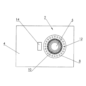
Referring firstly to Figures 1 to 4, a first embodiment of a rotary control
(2) of
the invention mounted on a surface (4) comprises a first rotatable body in the
form of
cylindrical knob (6) which includes a plurality of channels (10) disposed
around the
periphery of the cylindrical knob (6). The channels (10) include optic fibres,
which
are provided at one end with a light emitting diode (not shown). The channels
(10)
are formed as cut-out channels in the body of the cylindrical knob (6).
Formed around the cylindrical knob (6) is a second rotatable body in the form
of an annular knob (8) though which extend a plurality of channels (12), again
comprising optic fibres running therethrough, and connected to a light
emitting diode
at one end thereof.
The rotary control (2) is connected to a surface (4) of a music mixing desk
(not
shown), and the cylindrical knob (6) and annular knob (8) control parameters
associated with the music mixing desk, such as volume, stereo gain, volume
level
CA 02917445 2016-01-06
WO 2015/008092 PCT/GB2014/052214
filter frequency, filter cut, filter boost or frequency gain for example. In
this
embodiment the two knobs (6), (8) control different parameters.
The cylindrical knob (6) is connected to the surface (4) via a spindle (3) as
shown in Figures 2 and 3. The annular knob (8) is connected to the surface (4)
via a
5 retaining sleeve (7) as shown in Figure 3. The spindle (3) includes a
reader (5)
arranged to read the rotational position of the cylindrical knob (6) via any
suitable
means, connected to the inside surface of the cylindrical knob (6) such as a
mechanical or optical encoder. The reader (5) is connected to suitable
circuitry which
reads the rotational position of the cylindrical knob (6) enabling the
relevant
10 parameter state to be transmitted electronically to the LEDs of the
channels (10),
which light emitting diodes produce signals transmitted by the optic fibres in
channels
(10). Electronic circuitry is disposed between the spindle (3) and the LEDs of
the
channels (10) so that a variety of operative states can be displayed by the
fibre optics.
For example, where the control position simply represents the volume of a
particular
.. sound source, that volume can be represented by the progressive
illumination of
diodes from a zero reference point so that a curved eliminated line of
increasing or
decreasing length is produced as the control is turned to increase or decrease
the
volume. Alternatively, the volume change may be indicated by the change in
colour
of each LED as the volume increases or decreases. Specific permutations of
illuminated elements may be selected to represent specific operational
conditions. For
example, a castellated display, where every other diode is illuminated
progressively
can be used to indicate stereo gain for example.
The annular knob (8) includes a code strip (16) printed or engraved around the
outside of the annular knob (8). The code strip (16) is arranged to
operatively
cooperate with an optical reader (14) adjacent to the annular knob (8), via
suitable
circuitry, so that as the annular knob (8) is rotated, the optical reader (14)
reads signals
from the code strip, and transmits said signals, corresponding to the state of
the
parameter being adjusted, to the LEDs located or associated with the channels
(12). In
this way, rotation of the annular knob (8), which causes a parameter change,
sends
information to the optical reader (14), which in turn transmits the
information to the
LEDs in or associated with the channels (12), so that the state of the
relevant
parameter can be displayed by the LEDs located within the channels (12).
CA 02917445 2016-01-06
WO 2015/008092 PCT/GB2014/052214
11
In use, an operator may therefore rotate the cylindrical knob (6) and the
annular knob (8) in order to change specific parameters, which change is then
transmitted and displayed via the LEDs located within channels (10) and (12).
In
some examples, the parameters controlled by the cylindrical knob (6) and
annular
knob (8) arc complementary, such as, for example coarse and fine control of
volume
or high-pass and low-pass filters of specific signals. In this way, a
manufacturer of a
music mixing desk or other equipment can ensure that parameters commonly
adjusted
together by an operator can be incorporated into the same rotary control. As
the
reader (5) located on spindle (3) and the corresponding encoder on the
cylindrical
knob (6) are located within the rotary control, this also saves valuable space
on the
music mixing desk or other equipment. In alternative embodiments to that shown
in
Figures 1 to 4 the optical encoder (14) (or any external encoder) connected
with the
outer annular knob (8) may also be located within or beneath the rotary
control (2) in
order to save further space.
Referring now to Figures 5 to 8, in a second embodiment of a rotary control
(102) of the invention, the cylindrical knob (106), channels (110), annular
knob (108),
channels (112), surface (104), spindle (103). reader sleeve (105) and
retaining ring
(107) shown correspond to the same component as described for the embodiment
of
Figures 1-4, and their form and operation are identical.
In the embodiments shown in Figures 5-8, instead of an optical encoder and
code strip, a gear-mesh (120) is provided around the outside of the base of
the annular
knob (108), and a corresponding mechanical reader (118) is located adjacent to
the
gear-mesh (120). In use, operation of the rotary control (102) is identical to
that
described for the embodiment shown in Figures 1-4, with the exception that the
rotary
position of the annular knob (108) is determined via the mechanical reader
(118)
meshing with the gear-mesh (120), which then effects transmission of signals
via
circuitry to the LEDs of the channels (112).
Referring now to Figures 9 to 12, in a third embodiment of a rotary control
(202) of the invention, a cylindrical knob (206), channels (210), annular knob
(208),
channels (212), surface (204), spindle (203), spindle reader sleeve (205) and
retaining
ring (207) shown correspond to the same component as described for the
CA 02917445 2016-01-06
WO 2015/008092 PCT/GB2014/052214
12
embodiments of Figures 1-4 and 5-8, and their form and operation are
substantially
identical.
In the embodiments shown in Figures 9-12, instead of an optical or mechanical
reader located external to the annular knob (208), the encoder and
corresponding
reader associated with the annular knob (208) arc located within the rotary
control
(202). The encoder takes the form of an encoder ring (220) located on the
inside of
the surface of the annular knob (208), as shown in Figure 11. A corresponding
reader
is located on the exterior surface of the retaining sleeve (207), in the form
of a reader
strip (218), as shown in Figure 11. In use, operation of the rotary control
(202) is
identical to that described for the embodiment shown in Figures 1-4 or 5-8,
with the
exception that the rotary position of the annular knob (208) is determined via
the
reader (218) reading corresponding signals from the optical encoder (220) on
the
inside of the annular knob (208). The reader then effects transmission of
signals via
the circuitry to the LEDs of the channels (212).
The embodiments shown in Figures 9-12 does not include any external
components which further serves to minimise space on the surface (204) of the
apparatus, and in addition minimises the risk of any one rotary control (202),
malfunctioning due to obscuration of an external reader, by dust, or other
foreign
objects.
Referring now to Figure 13, in a fourth embodiment of a rotary control (302)
of the invention, a cylindrical knob (306) and annular knob (308) shown
correspond to
the same component as described for the embodiments of Figures 1-4, 5-8, and 9-
12,
and their form and operation are substantially identical.
Channels (310, 312) again comprise optic fibres running therethrough
however, the fibres are not connected to a single LED at an end thereof.
Rather, the
fourth embodiment of the rotary control (302) comprises an array of LEDs (320)
arranged in a pair of concentric circles (322, 324). The cylindrical knob
(306) and the
annular knob (308) sit directly above the array (320), with the inner circle
(322)
corresponding to the channels (310) of the cylindrical knob (306), and the
outer circle
(324) corresponding to the channels (312) of the annular knob (308). In this
embodiment, the cylindrical knob (306) and the annular knob (308) are
rotatable with
respect to the array of LEDs (320). In this way, the light from each of the
LEDs
CA 02917445 2016-01-06
WO 2015/008092 PCT/GB2014/052214
13
making up the array (320) may at some point be transmitted through each of the
channels (310, 312), depending on the position of the knobs (306, 308).
The rotary control (302) further includes a reader (303) arranged to read the
rotational position of the cylindrical knob (306) via any suitable means,
connected to
the inside surface of the cylindrical knob (306) such as a mechanical or
optical
encoder. The reader (303) is connected to suitable circuitry which reads the
rotational
position of the cylindrical knob (306) enabling the relevant parameter state
to be
transmitted electronically to the LEDs of the inner circle (322) of the array
(320).
which light emitting diodes produce signals transmitted by the optic fibres in
channels
(310). Electronic circuitry is disposed between the reader (303) and the LEDs
so that
a variety of operative states can be displayed by the fibre optics.
The annular knob (308) includes a code strip (316) printed or engraved around
the outside of the annular knob (308). The code strip (316) is arranged to
operatively
cooperate with an optical reader (314) adjacent to the annular knob (8). via
suitable
circuitry, so that as the annular knob (308) is rotated, the optical reader
(314) reads
signals from the code strip, and transmits said signals, corresponding to the
state of
the parameter being adjusted, to the LEDs on the outer circle (324) of the
array (320).
In this way, rotation of the annular knob (308), which causes a parameter
change,
sends information to the optical reader (314), which in turn transmits the
information
to the LEDs associated with the channels (312), so that the state of the
relevant
parameter can be displayed by the channels (312).
In addition to the above, both the cylindrical knob (306) and the annular knob
(308) comprise respective surfaces (307, 309) which are touch sensitive. The
touch
sensitive surfaces (307, 309) are connected to suitable circuitry which
enables the
relevant parameter to he controlled without rotating the relevant knob (306,
308). The
state of the relevant parameter controlled through the operation of the
surfaces (307,
309) may also be transmitted electronically to the LEDs of the corresponding
circle
(322, 324) of the array (320) such that the state of the controllable
parameters is
displayed.
The rotary control (302) may further comprise a means to store the operational
state or a series of operational states of each controllable parameter. In
this way, the
stored parameter settings or series of settings may subsequently be recalled
without a
CA 02917445 2016-01-06
WO 2015/008092 PCT/GB2014/052214
14
user having to rotate each rotatable body (306, 308) or contact the touch
sensitive
surface/s (307, 309) to input each parameter setting individually to return to
a desired
setting. When recalling the stored parameter settings or series of settings,
the rotary
control (302) may further be operable to reactivate the corresponding LEDs.
The rotary control (302) may further comprise a microprocessor in
communication with a remote computer. The controllable parameters and/or the
operation of the visual display elements may be controlled by the
microprocessor.
The microprocessor may control the rotation of each rotatable body (306, 308)
and/or
the operation of the LEDs and may do so upon receipt of instructions from the
remote
computer.
The control of the parameters may be fully automated by the microprocessor
and computer, for example, a user may input desired parameter settings
directly to the
computer and without the need to use the rotatable bodies (306, 308) of the
rotary
control (302). The computer may subsequently relay the user inputs to the
microprocessor which controls the parameters through control of the rotation
of the
rotatable bodies (306, 308) and/or the operation of the LEDs.
The provision of touch sensitive surfaces (307, 309) on the rotatable bodies
(306, 308) as illustrated in Figure 13 affords additional benefits in
embodiments
wherein the parameter settings are controlled automatically by a
microprocessor and a
computer. During automation of the settings. a user may wish to override the
computer to either adjust or turn on/off the parameter setting/s and/or LEDs.
By
providing touch sensitive surfaces (307. 309) on the rotatable bodies (306.
308) this
allows for greater control over the parameter settings, even during
automation. For
example, activation of the or each touch sensitive surface (307, 309) may
switch the
rotary control (302) from being controlled by the remote computer, to being
controlled
by the user directly and vice versa. In other embodiments, the channels of the
cylindrical knob (6, 106. 206, 306) may be replaced with a display formed from
a
matrix of light emitting elements within the top surface of the knob (6, 106,
206, 306),
the matrix may be square or circular, or tailored to the shape the knob (6,
106, 206,
306). A display control is associated with the display. The matrix may
comprise a
plurality of light emitting diodes, liquid crystal display elements or pixels.
These
elements/pixels may he polygonal, for example hexagonal, as the image/knob may
CA 02917445 2016-01-06
WO 2015/008092 PCT/GB2014/052214
stop in any position. hi one form the diodes or elements have an area of
0.3mm2 and
spaced apart about 0.05mm2. An arrangement having a matrix, rather than an
annular
ring of light emitting elements enables the visual information displayed
relating to a
parameter to be in the form of numerals, letters, images or the like, which
may be
5 preferred by some operators.
In other embodiments, the channels located in both knobs (6, 106, 206, 306, 8,
108, 208, 308) may be replaced by a single appropriately positioned light
emitting
element or a plurality of light emitting elements, which change in response to
a
change in the relevant parameter, the change being a change in colour,
brightness, or
10 .. otherwise.
In an alternative embodiment, the rotatable bodies (306, 308) may be non-
rotatable and changing each parameter may be achieved by touch-sensitive
manipulation of the touch-sensitive surfaces (307, 309) alone. In these
embodiments
a user would move his or her finger across the touch-sensitive surfaces (307,
309) to
15 actuate changes in the relevant parameters, and this movement would be
transmitted
to the visual display elements such as the corresponding circle (322, 324) of
the array
(320) to display the states of the controllable parameters.
The above embodiments are described by way of example only. Many
variations are possible without departing from the scope of the invention as
defined in
the appended claims.