Note: Descriptions are shown in the official language in which they were submitted.
CA 02917532 2015-12-11
WO 2014/207576 PCT/1B2014/002158
1
IMPLANT UNIT DELIVERY TOOL
DESCRIPTION
RELATED APPLICATIONS
[001] This application is a continuation-in-part of U.S. Patent
Application No. 13/952,082, filed July 26, 2013 and U.S. Patent Application
No, 13/952,031, filed July 26, 2013, and claims the benefit of priority under
35
U.S.C. 119(e) to U.S, Provisional Application No. 61/836,089, filed June 17,
2013. Each of the above-referenced applications is incorporated herein by
reference,
TECHNICAL FIELD
[002] Embodiments of the present disclosure generally relate to
devices and methods for modulating a nerve. More particularly, embodiments
of the present disclosure relate to devices and methods for delivering an
implantable device to a location suitable for neural modulation,
BACKGROUND
[003] Neural modulation presents the opportunity to treat many
physiological conditions and disorders by interacting with the body's own
natural neural processes. Neural modulation includes inhibition (e.g.
blockage), stimulation, modification, regulation, or therapeutic alteration of
activity, electrical or chemical, in the central, peripheral, or autonomic
nervous
system. By modulating the activity of the nervous system, for example
through the stimulation of nerves or the blockage of nerve signals, several
different goals may be achieved. Motor neurons may be stimulated at
appropriate times to cause muscle contractions. Sensory neurons may be
blocked, for instance to relieve pain, or stimulated, for instance to provide
a
signal to a subject. in other examples, modulation of the autonomic nervous
system may be used to adjust various involuntary physiological parameters,
such as heart rate and blood pressure. Neural modulation may provide the
opportunity to treat several diseases or physiological conditions, a few
examples of which are described in detail below.
CA 02917532 2015-12-11
WO 2014/207576 PCT/1B2014/002158
2
[004] Among the conditions to which neural modulation may be
applied are sleep related breathing disorders, such as snoring and obstructive
sleep apnea (OSA). OSA is a respiratory disorder characterized by recurrent
episodes of partial or complete obstruction of the upper airway during sleep.
During the sleep of a person without OSA, the pharyngeal muscles relax
during sleep and gradually collapse, narrowing the airway. The airway
narrowing limits the effectiveness of the sleeper's breathing, causing a rise
in
CO2 levels in the blood. The increase in CO2 results in the pharyngeal
muscles contracting to open the airway to restore proper breathing. The
largest of the pharyngeal muscles responsible for upper airway dilation is the
genioglossus muscle, which is one of several different muscles in the tongue.
The genioglossus muscle is responsible for forward tongue movement and
the stiffening of the anterior pharyngeal wall. In patients with OSA, the
neuromuscular activity of the genioglossus muscle is decreased compared to
normal individuals, accounting for insufficient response and contraction to
open the airway as compared to a normal individual. This lack of response
contributes to a partial or total airway obstruction, which significantly
limits the
effectiveness of the sleeper's breathing. In OSA patients, there are often
several airway obstruction events during the night. Because of the
obstruction, there is a gradual decrease of oxygen levels in the blood
(hypoxemia). Hypoxemia leads to night time arousals, which may be
registered by EEG, showing that the brain awakes from any stage of sleep to
a short arousal. During the arousal, there is a conscious breath or gasp,
which resolves the airway obstruction. An increase in sympathetic tone
activity rate through the release of hormones such as epinephrine and
noradrenaline also often occurs as a response to hypoxemia. As a result of
the increase in sympathetic tone, the heart enlarges in an attempt to pump
more blood and increase the blood pressure and heart rate, further arousing
the patient. After the resolution of the apnea event, as the patient returns
to
sleep, the airway collapses again, leading to further arousals.
[005] These repeated arousals, combined with repeated hypoxemia,
leaves the patient sleep deprived, which leads to daytime somnolence and
worsens cognitive function. This cycle can repeat itself up to hundreds of
times per night in severe patients. Thus, the repeated fluctuations in and
CA 02917532 2015-12-11
WO 2014/207576 PCT/1B2014/002158
3
sympathetic tone and episodes of elevated blood pressure during the night
evolve to high blood pressure through the entire day. Subsequently, high
blood pressure and increased heart rate may cause other diseases.
[006] Snoring in patients is frequently a result of a partially obstructed
airway. Some patients experience relaxation of the pharyngeal muscles to a
point that involves partial obstruction not significant enough to cause
subsequent arousals during sleep. When the pharyngeal muscles relax and
narrow the airway, air must travel through the airway at a higher velocity to
maintain a similar volumetric flow rate. Higher velocity flows are more likely
to
be turbulent. These turbulent flows can cause vibrations in the tissue
structure of the airway, producing an audible snoring effect, Snoring may
have several adverse effects on both sufferers and those around them.
Snoring may lead to hypopnea, a condition in which blood oxygen levels are
decreased; resulting in shallower, less restful sleep. Snoring may also be
associated with an increased risk of stroke and carotid artery
atherosclerosis.
Additionally, snoring may be detrimental to the sleep of those around the
sufferer.
[007] Efforts for treating both snoring and OSA include Continuous
Positive Airway Pressure (CPAP) treatment, which requires the patient to
wear a mask through which air is blown into the nostrils to keep the airway
open. Other treatment options include the implantation of rigid inserts in the
soft palate to provide structural support, tracheotomies, or tissue ablation.
[008] Another condition to which neural modulation may be applied is
the occurrence of migraine headaches. Pain sensation in the head is
transmitted to the brain via the occipital nerve, specifically the greater
occipital
nerve, and the trigeminal nerve. When a subject experiences head pain ,
such as during a migraine headache; the inhibition of these nerves may serve
to decrease or eliminate the sensation of pain.
[009] Neural modulation may also be applied to hypertension. Blood
pressure in the body is controlled via multiple feedback mechanisms. For
example, baroreceptors in the carotid body in the carotid artery are sensitive
to blood pressure changes within the carotid artery. The baroreceptors
generate signals that are conducted to the brain via the glossopharyngeal
nerve when blood pressure rises, signaling the brain to activate the body's
CA 02917532 2015-12-11
WO 2014/207576 PCT/1B2014/002158
4
regulation system to lower blood pressure, e.g. through changes to heart rate,
and vasodilation/vasoconstriction. Conversely, parasympathetic nerve fibers
on and around the renal arteries generate signals that are carried to the
kidneys to initiate actions, such as salt retention and the release of
angiotensin, which raise blood pressure. Modulating these nerves may
provide the ability to exert some external control over blood pressure.
[010] The foregoing are just a few examples of conditions to which
neuromodulation may be of benefit, however embodiments of the invention
described hereafter are not necessarily limited to treating only the above-
described conditions.
SUMMARY
[011] Some embodiments include an implant unit delivery tool. The
implant delivery tool includes a body, a holder disposed at a distal end of
the
body and adapted to hold an implant unit, and an implant activator associated
with the body, the implant activator configured to receive power from a power
source. The the implant activator may be configured to selectively and
wirelessly transfer power from the power source to the implant unit during
implantation of the implant unit into the body of a subject to cause
modulation
of at least one nerve in the body of the subject, and determine a degree of
nerve modulation response resulting from the selective and wireless transfer
of power from the power source to the implant unit claims.
[012] Additional features of the disclosure will be set forth in part in the
description that follows, and in part will be obvious from the description, or
may be learned by practice of the disclosed embodiments.
[013] It is to be understood that both the foregoing general description
and the following detailed description are exemplary and explanatory only,
and are not restrictive of the invention, as claimed.
BRIEF DESCRIPTION OF THE DRAWINGS
[014] The accompanying drawings, which are incorporated in and
constitute a part of this specification, illustrate several embodiments of the
disclosure and, together with the description, serve to explain the principles
of
the embodiments disclosed herein.
CA 02917532 2015-12-11
WO 2014/207576 PCT/1B2014/002158
[015] Figure 1 schematically illustrates an implant unit and external
unit, according to an exemplary embodiment of the present disclosure.
[016] Figure 2 is a partially cross-sectioned side view of a subject with
an implant unit and external unit, according to an exemplary embodiment of
the present disclosure.
[017] Figure 3 schematically illustrates a system including an implant
unit and an external unit, according to an exemplary embodiment of the
present disclosure.
[018] Figure 4 is a top view of an implant unit, according to an
exemplary embodiment of the present disclosure,
[019] Figures 5a-b are top views of alternate embodiments of an
implant unit, according to exemplary embodiments of the present disclosure.
[020] Figure 6 illustrates circuitry of an implant unit and an external
unit, according to an exemplary embodiment of the present disclosure.
[021] Figure 7 illustrates a graph of quantities that may be used in
determining energy delivery as a function coupling, according to an exemplary
disclosed embodiment.
[022] Figure 8a illustrates a pair of electrodes spaced apart from one
another along the longitudinal direction of nerve to facilitate generation of
an
electric field having field lines substantially parallel to the longitudinal
direction
of nerve.
[023] Figure 8b illustrates an embodiment wherein electrodes are
spaced apart from one another in a longitudinal direction of at least a
portion
of nerve.
[024] Figure. 8c illustrates a situation wherein electrodes are spaced
apart from one another in a transverse direction of nerve.
[025] Figure 9 illustrates effects of electrode configuration on the
shape of a generated electric field.
[026] Figure 10 is illustrates additional features of one embodiment of
implant unit.
[027] Figure 11 depicts anatomy of the tongue and associated
muscles and nerves.
[028] Figure 12 illustrates an exemplary implantation position for an
implant unit.
CA 02917532 2015-12-11
WO 2014/207576 PCT/1B2014/002158
6
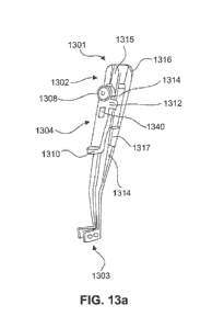
[029] Figures 13a-13c illustrate various aspects of a delivery tool.
[030] Figures 14a-14c illustrates various aspects of a delivery tool
[031] Figure 15 depicts features of a delivery tool implant holder
portion.
DESCRIPTION OF EXEMPLARY EMBODIMENTS
[032] Reference will now be made in detail to exemplary embodiments
of the present disclosure, examples of which are illustrated in the
accompanying drawings. Wherever possible, the same reference numbers
will be used throughout the drawings to refer to the same or like parts.
[033] Embodiments of the present disclosure relate generally to
devices for modulating a nerve through the delivery of energy. Nerve
modulation, or neural modulation, includes inhibition (e.g. blockage),
stimulation, modification, regulation, or therapeutic alteration of activity,
electrical or chemical, in the central, peripheral, or autonomic nervous
system.
Nerve modulation may take the form of nerve stimulation, which may include
providing energy to the nerve to create a voltage change sufficient for the
nerve to activate, or propagate an electrical signal of its own. Nerve
modulation may also take the form of nerve inhibition, which may including
providing energy to the nerve sufficient to prevent the nerve from propagating
electrical signals. Nerve inhibition may be performed through the constant
application of energy, and may also be performed through the application of
enough energy to inhibit the function of the nerve for some time after the
application. Other forms of neural modulation may modify the function of a
nerve, causing a heightened or lessened degree of sensitivity. As referred to
herein, modulation of a nerve may include modulation of an entire nerve
and/or modulation of a portion of a nerve. For example, modulation of a
motor neuron may be performed to affect only those portions of the neuron
that are distal of the location to which energy is applied.
[034] In patients that suffer from a sleep breathing disorder, for
example, a primary target response of nerve stimulation may include
contraction of a tongue muscle (e.g., the muscle) in order to move the tongue
to a position that does not block the patient's airway. In the treatment of
migraine headaches, nerve inhibition may be used to reduce or eliminate the
CA 02917532 2015-12-11
WO 2014/207576 PCT/1B2014/002158
7
sensation of pain. In the treatment of hypertension, neural modulation maybe
used to increase, decrease, eliminate or otherwise modify nerve signals
generated by the body to regulate blood pressure.
[035] While embodiments of the present disclosure may be disclosed
for use in patients with specific conditions, the embodiments may be used in
conjunction with any patient/portion of a body where nerve modulation may be
desired. That is, in addition to use in patients with a sleep breathing
disorder ,
migraine headaches, or hypertension, embodiments of the present disclosure
may be used in many other areas, including, but not limited to: deep brain
stimulation (e.g,, treatment of epilepsy, Parkinson's, and depression);
cardiac
pace-making, stomach muscle stimulation (e.g., treatment of obesity), back
pain, incontinence, menstrual pain, and/or any other condition that may be
affected by neural modulation.
[036] Figure 1 illustrates an implant unit and external unit, according
to an exemplary embodiment of the present disclosure. An implant unit 110,
may be configured for implantation in a subject, in a location that permits it
to
modulate a nerve 115. The implant unit 110 may be located in a subject such
that intervening tissue 111 exists between the implant unit 110 and the nerve
115. Intervening tissue may include muscle tissue, connective tissue, organ
tissue, or any other type of biological tissue. Thus, location of implant unit
110 does not require contact with nerve 115 for effective neuromodulation.
The implant unit 110 may also be located directly adjacent to nerve 116, such
that no intervening tissue 111 exists.
[037] In treating a sleep breathing disorder, implant unit 110 may be
located on a genioglossus muscle of a patient. Such a location is suitable for
modulation of the hypoglossal nerve, branches of which run inside the
genioglossus muscle. Implant unit 110 may also be configured for placement
in other locations. For example, migraine treatment may require
subcutaneous implantation in the back of the neck, near the hairline of a
subject, or behind the ear of a subject, to modulate the greater occipital
nerve
and/or the trigeminal nerve. Treating hypertension may require the
implantation of a neuromodulation implant intravascularly inside the renal
artery or renal vein (to modulate the parasympathetic renal nerves), either
unilaterally or bilaterally, inside the carotid artery or jugular vein (to
modulate
CA 02917532 2015-12-11
WO 2014/207576 PCT/1B2014/002158
8
the glossopharyngeal nerve through the carotid baroreceptors). Alternatively
or additionally, treating hypertension may require the implantation of a
neuromodulation implant subcutaneously, behind the ear or in the neck, for
example, to directly modulate the glossopharyngeal nerve.
[038] External unit 120 may be configured for location external to a
patient, either directly contacting, or close to the skin 112 of the patient.
External unit 120 may be configured to be affixed to the patient, for example,
by adhering to the skin 112 of the patient, or through a band or other device
configured to hold external unit 120 in place. Adherence to the skin of
external unit 120 may occur such that it is in the vicinity of the location of
implant unit 110.
[039] Figure 2 illustrates an exemplary embodiment of a
neuromodulation system for delivering energy in a patient 100 with a sleep
breathing disorder. The system may include an external unit 120 that may be
configured for location external to the patient. As illustrated in Figure 2,
external unit 120 may be configured to be affixed to the patient 100. Figure 2
illustrates that in a patient 100 with a sleep breathing disorder, the
external
unit 120 may be configured for placement underneath the patient's chin
and/or on the front of patient's neck. The suitability of placement locations
may be determined by communication between external unit 120 and implant
unit 110, discussed in greater detail below. In alternate embodiments, for the
treatment of conditions other than a sleep breathing disorder, the external
unit
may be configured to be affixed anywhere suitable on a patient, such as the
back of a patient's neck, i.e. for communication with a migraine treatment
implant unit, on the outer portion of a patient's abdomen, i.e. for
communication with a stomach modulating implant unit, on a patient's back,
i.e. for communication with a renal artery modulating implant unit, and/or on
any other suitable external location on a patients skin, depending on the
requirements of a particular application.
[040] External unit 120 may further be configured to be affixed to an
alternative location proximate to the patient. For example, in one
embodiment, the external unit may be configured to fixedly or removably
adhere to a strap or a band that may be configured to wrap around a part of a
patient's body. Alternatively, or in addition, the external unit may be
CA 02917532 2015-12-11
WO 2014/207576 PCT/1B2014/002158
9
configured to remain in a desired location external to the patient's body
without adhering to that location.
[041] The external unit 120 may include a housing. The housing may
include any suitable container configured for retaining components. In
addition, while the external unit is illustrated schematically in Fig. 2, the
housing may be any suitable size and/or shape and may be rigid or flexible.
Non-limiting examples of housings for the external unit 100 include one or
more of patches, buttons, or other receptacles having varying shapes and
dimensions and constructed of any suitable material. In one embodiment, for
example, the housing may include a flexible material such that the external
unit may be configured to conform to a desired location. For example, as
illustrated in Figure 2, the external unit may include a skin patch, which, in
turn, may include a flexible substrate. The material of the flexible substrate
may include, but is not limited to, plastic, silicone, woven natural fibers,
and
other suitable polymers, copolymers, and combinations thereof. Any portion
of external unit 120 may be flexible or rigid, depending on the requirements
of
a particular application.
[042] As previously discussed, in some embodiments external unit
120 may be configured to adhere to a desired location. Accordingly, in some
embodiments, at least one side of the housing may include an adhesive
material. The adhesive material may include a biocompatible material and
may allow for a patient to adhere the external unit to the desired location
and
remove the external unit upon completion of use. The adhesive may be
configured for single or multiple uses of the external unit. Suitable adhesive
materials may include, but are not limited to biocompatible glues, starches,
elastomers, thermoplastics, and emulsions.
[043] Figure 3 schematically illustrates a system including external
unit 120 and an implant unit 110. In some embodiments, internal unit 110
may be configured as a unit to be implanted into the body of a patient, and
external unit 120 may be configured to send signals to and/or receive signals
from implant unit 110.
[044] As shown in Figure 3, various components may be included
within a housing of external unit 120 or otherwise associated with external
unit
120. As illustrated in Figure 3, at least one processor 144 may be associated
CA 02917532 2015-12-11
WO 2014/207576 PCT/1B2014/002158
with external unit 120. For example, the at least one processor 144 may be
located within the housing of external unit 120. In alternative embodiments,
the at least one processor may be configured for wired or wireless
communication with the external unit from a location external to the housing.
[045] The at least one processor may include any electric circuit that
may be configured to perform a logic operation on at least one input variable.
The at least one processor may therefore include one or more integrated
circuits, microchips, microcontrollers, and microprocessors, which may be all
or part of a central processing unit (CPU), a digital signal processor (DSP),
a
field programmable gate array (FPGA). or any other circuit known to those
skilled in the art that may be suitable for executing instructions or
performing
logic operations.
[046] Figure 3 illustrates that the external unit 120 may further be
associated with a power source 140. The power source may be removably
couplable to the external unit at an exterior location relative to external
unit.
Alternatively, as shown in Figure 3, power source 140 may be permanently or
removably coupled to a location within external unit 120. The power source
may further include any suitable source of power configured to be in
electrical
communication with the processor. In one embodiment, for example the
power source 140 may include a battery.
[047] The power source may be configured to power various
components within the external unit. As illustrated in Figure 3, power source
140 may be configured to provide power to the processor 144. In addition,
the power source 140 may be configured to provide power to a signal source
142. The signal source 142 may be in communication with the processor 144
and may include any device configured to generate a signal (e.g., a sinusoidal
signal, square wave, triangle wave, microwave, radio-frequency (RE) signal,
or any other type of electromagnetic signal). Signal source 142 may include,
but is not limited to, a waveform generator that may be configured to generate
alternating current (AC) signals and/or direct current (DC) signals. In one
embodiment, for example, signal source 142 may be configured to generate
an AC signal for transmission to one or more other components. Signal
source 142 may be configured to generate a signal of any suitable frequency.
In some embodiments, signal source 142 may be configured to generate a
CA 02917532 2015-12-11
WO 2014/207576 PCT/1B2014/002158
11
signal having a frequency of from about 6.5 MHz to about 13.6 MHz. In
additional embodiments, signal source 142 may be configured to generate a
signal having a frequency of from about 7.4 to about 8.8 MHz. In further
embodiments, signal source 142 may generate a signal having a frequency as
low as 90 kHz or as high as 28 MHz.
[048] Signal source 142 may be configured for direct or indirect
electrical communication with an amplifier 146. The amplifier may include any
suitable device configured to amplify one or more signals generated from
signal source 142. Amplifier 146 may include one or more of various types of
amplification devices, including, for example, transistor based devices,
operational amplifiers, RE amplifiers, power amplifiers, or any other type of
device that can increase the gain associated one or more aspects of a signal.
The amplifier may further be configured to output the amplified signals to one
or more components within external unit 120.
[049] The external unit may additionally include a primary antenna
150. The primary antenna may be configured as part of a circuit within
external unit 120 and may be coupled either directly or indirectly to various
components in external unit 120. For example. as shown in Figure 3, primary
antenna 150 may be configured for communication with the amplifier 146.
[050] The primary antenna may include any conductive structure that
may be configured to create an electromagnetic field. The primary antenna
may further be of any suitable size, shape, and/or configuration. The size,
shape, and/or configuration may be determined by the size of the patient, the
placement location of the implant unit, the size and/or shape of the implant
unit, the amount of energy required to modulate a nerve, a location of a nerve
to be modulated, the type of receiving electronics present on the implant
unit,
etc. The primary antenna may include any suitable antenna known to those
skilled in the art that may be configured to send and/or receive signals.
Suitable antennas may include, but are not limited to, a long-wire antenna, a
patch antenna, a helical antenna, etc. In one embodiment, for example, as
illustrated in Figure 3, primary antenna 150 may include a coil antenna. Such
a coil antenna may be made from any suitable conductive material and may
be configured to include any suitable arrangement of conductive coils (e.g.,
diameter, number of coils, layout of coils, etc.). A coil antenna suitable for
use
CA 02917532 2015-12-11
WO 2014/207576 PCT/1B2014/002158
12
as primary antenna 150 may have a diameter of between about 1 cm and 10
cm, and may be circular or oval shaped. In some embodiments, a coil
antenna may have a diameter between 5 cm and 7 cm, and may be oval
shaped. A coil antenna suitable for use as primary antenna 150 may have
any number of windings, e.g. 4, 8, 12, or more. A coil antenna suitable for
use as primary antenna 150 may have a wire diameter between about 0.1 mm
and 2 mm. These antenna parameters are exemplary only, and may be
adjusted above or below the ranges given to achieve suitable results.
[051] As noted, implant unit 110 may be configured to be implanted in
a patient's body (e.g., beneath the patient's skin). Figure 2 illustrates that
the
implant unit 110 may be configured to be implanted for modulation of a nerve
associated with a muscle of the subject's tongue 130. Modulating a nerve
associated with a muscle of the subject's tongue 130 may include stimulation
to cause a muscle contraction. In further embodiments, the implant unit may
be configured to be placed in conjunction with any nerve that one may desire
to modulate. For example, modulation of the occipital nerve, the greater
occipital nerve, and/or the trigeminal nerve may be useful for treating pain
sensation in the head, such as that from migraines. Modulation of
parasympathetic nerve fibers on and around the renal arteries (i.e.. the renal
nerves), the vagus nerve, and for the glossopharyngeal nerve may be useful
for treating hypertension. Additionally, any nerve of the peripheral nervous
system (both spinal and cranial), including motor neurons, sensory neurons,
sympathetic neurons and parasympathetic neurons, may be modulated to
achieve a desired effect.
[052] Implant unit 110 may be formed of any materials suitable for
implantation into the body of a patient. In some embodiments, implant unit
110 may include a flexible carrier 161 (Figure 4) including a flexible,
biocompatible material. Such materials may include, for example, silicone,
polyimides, phenyltrimethoxysilane (PTMS), polymethyl methacrylate
(PMMA), Parylene C, polyimide, liquid polyimide, laminated polyimide, black
epoxy, polyether ether ketone (PEEK), Liquid Crystal Polymer (LOP), Kapton,
etc. Implant unit 110 may further include circuitry including conductive
materials, such as gold, platinum, titanium, or any other biocompatible
conductive material or combination of materials. Implant unit 110 and flexible
CA 02917532 2015-12-11
WO 2014/207576 PCT/1B2014/002158
13
carrier 161 may also be fabricated with a thickness suitable for implantation
under a patient's skin. Implant 110 may have thickness of less than about 4
mm or less than about 2 mm.
[053] Other components that may be included in or otherwise
associated with the implant unit are illustrated in Figure 3. For example,
implant unit 110 may include a secondary antenna 152 mounted onto or
integrated with flexible carrier 161. Similar to the primary antenna, the
secondary antenna may include any suitable antenna known to those skilled
in the art that may be configured to send and/or receive signals. The
secondary antenna may include any suitable size, shape, and/or
configuration. The size, shape and/or configuration may be determined by the
size of the patient, the placement location of the implant unit, the amount of
energy required to modulate the nerve, etc. Suitable antennas may include,
but are not limited to, a long-wire antenna, a patch antenna, a helical
antenna,
etc. In some embodiments, for example, secondary antenna 152 may include
a coil antenna having a circular shape (see also Figure 4) or oval shape. Such
a coil antenna may be made from any suitable conductive material and may
be configured to include any suitable arrangement of conductive coils (e.g.,
diameter, number of coils, layout of coils, etc.). A coil antenna suitable for
use
as secondary antenna 152 may have a diameter of between about 5 mm and
30 mm, and may be circular or oval shaped. A coil antenna suitable for use
as secondary antenna 152 may have any number of windings, e.g. 4, 15, 20,
30, or 50. A coil antenna suitable for use as secondary antenna 152 may
have a wire diameter between about 0.01 mm and 1 mm. These antenna
parameters are exemplary only, and may be adjusted above or below the
ranges given to achieve suitable results.
[054]
[055] Implant unit 110 may additionally include a plurality of field-
generating implant electrodes 158a, 158b. The electrodes may include any
suitable shape and/or orientation on the implant unit so long as the
electrodes
may be configured to generate an electric field in the body of a patient.
Implant electrodes 158a and 158b may also include any suitable conductive
material (e.g., copper, silver, gold, platinum, iridium, platinum-iridium,
platinum-gold, conductive polymers, etc.) or combinations of conductive
CA 02917532 2015-12-11
WO 2014/207576 PCT/1B2014/002158
14
(and/or noble metals) materials. In some embodiments, for example, the
electrodes may include short line electrodes, circular electrodes, and/or
circular pairs of electrodes. As shown in Figure 4, electrodes 158a and 158b
may be located on an end of a first extension 162a of an elongate arm 162.
The electrodes, however, may be located on any portion of implant unit 110,
Additionally, implant unit 110 may include electrodes located at a plurality
of
locations, for example on an end of both a first extension 162a and a second
extension 162b of elongate arm 162, as illustrated, for example, in Figure 5.
Positioning electrodes on two extensions of elongate arm 162 may permit
bilateral hypoglossal nerve stimulation, as discussed further below, Implant
electrodes may have a thickness between about 200 nanometers and 1
millimeter. Anode and cathode electrode pairs may be spaced apart by about
a distance of about 0.2 mm to 25 mm. In additional embodiments, anode and
cathode electrode pairs may be spaced apart by a distance of about 1 mm to
mm, or between 4 mm and 7 mm. Adjacent anodes or adjacent cathodes
may be spaced apart by distances as small as 0.001 ram or less, or as great
as 25 mm or more. In some embodiments, adjacent anodes or adjacent
cathodes may be spaced apart by a distance between about 0.2 mm and 1
mm.
[056] Figure 4 provides a schematic representation of an exemplary
configuration of implant unit 110. As illustrated in Figure 4, in one
embodiment, the field-generating electrodes 158a and 158b may include two
sets of four circular electrodes, provided on flexible carrier 161, with one
set of
electrodes providing an anode and the other set of electrodes providing a
cathode. Implant unit 110 may include one or more structural elements to
facilitate implantation of implant unit 110 into the body of a patient. Such
elements may include, for example, elongated arms, suture holes, polymeric
surgical mesh, biological glue, spikes of flexible carrier protruding to
anchor to
the tissue, spikes of additional biocompatible material for the same purpose,
etc. that facilitate alignment of implant unit 110 in a desired orientation
within
a patient's body and provide attachment points for securing implant unit 110
within a body. For example, in some embodiments, implant unit 110 may
include an elongate arm 162 having a first extension 162a and, optionally, a
second extension 162b. Extensions 162a and 162b may aid in orienting
CA 02917532 2015-12-11
WO 2014/207576 PCT/1B2014/002158
implant unit 110 with respect to a particular muscle (e.g., the genioglossus
muscle), a nerve within a patient's body, or a surface within a body above a
nerve. For example, first and second extensions 162a, 162b may be
configured to enable the implant unit to conform at least partially around
soft
or hard tissue (e.g., nerve, bone, or muscle, etc.) beneath a patient's skin.
Further, implant unit 110 may also include one or more suture holes 160
located anywhere on flexible carrier 161. For example, in some
embodiments, suture holes 160 may be placed on second extension 162b of
elongate arm 162 and/or on first extension 162a of elongate arm 162.
Implant unit 110 may be constructed in various shapes. Additionally, or
alternatively, implant unit 110 may include surgical mesh 1050 or other
perforatable material, described in greater detail below with respect to Fig.
10.
In some embodiments, implant unit may appear substantially as illustrated in
Figure 4. In other embodiments, implant unit 110 may lack illustrated
structures such as second extension 162b, or may have additional or different
structures in different orientations. Additionally, implant unit 110 may be
formed with a generally triangular, circular, or rectangular shape, as an
alternative to the winged shape shown in Figure 4. In some embodiments,
the shape of implant unit 110 (e.g., as shown in Figure 4) may facilitate
orientation of implant unit 110 with respect to a particular nerve to be
modulated, Thus, other regular or irregular shapes may be adopted in order
to facilitate implantation in differing parts of the body.
[057] As illustrated in Figure 4, secondary antenna 152 and
electrodes 158a, 158b may be mounted on or integrated with flexible carrier
161. Various circuit components and connecting wires (discussed further
below) may be used to connect secondary antenna with implant electrodes
158a and 158b. To protect the antenna, electrodes, circuit components, and
connecting wires from the environment within a patient's body, implant unit
110 may include a protective coating that encapsulates implant unit 110. In
some embodiments, the protective coating may be made from a flexible
material to enable bending along with flexible carrier 161. The encapsulation
material of the protective coating may also resist humidity penetration and
protect against corrosion. In some embodiments, the protective coating may
CA 02917532 2015-12-11
WO 2014/207576 PCT/1B2014/002158
16
include a plurality of layers, including different materials or combinations
of
materials in different layers.
[058] In some embodiments, all or some of the circuitry components
included in implant 110 may be housed in a ceramic housing. Such a housing
may be a ceramic clamshell, and may be welded closed with a biocompatible
metal such as gold or titanium. A ceramic housing may protect the
components of implant 110 from the environment within the body. A ceramic
housing may be further encapsulated with a material used for encapsulating
the rest of implant unit 110, as described above.
[059] Figure 5a is a perspective view of an alternate embodiment of
an implant unit 110, according to an exemplary embodiment of the present
disclosure. As illustrated in Figure 5a, implant unit 110 may include a
plurality
of electrodes, located, for example, at the ends of first extension 162a and
second extension 162b. Figure 5a illustrates an embodiment wherein implant
electrodes 158a and 158b include short line electrodes.
[060] Fig. 5b illustrates another alternate embodiment of implant unit
810: according to an exemplary embodiment of the present disclosure.
Implant unit 810 is configured such that circuitry 880 is located in a
vertical
arrangement with secondary antenna 852. Implant unit 810 may include first
extension 162a and second extension 162b, wherein one or both of the
extensions accommodate electrodes 158a and 158b.
[061] Also illustrated in Fig. 10 is encapsulated surgical mesh 1050.
Surgical mesh 1050 may provide a larger target area for surgeons to use
when suturing implant unit 110 into place during implantation. The entire
surgical mesh 1050 may be encapsulated by primary capsule 1021, permitting
a surgeon to pass a needle through any portion of the mesh without
compromising the integrity of implant unit 110. Surgical mesh 1050 may
additionally be used to cover suture holes 160, permitting larger suture holes
160 that may provide surgeons with a greater target area. Surgical mesh
1050 may also encourage surrounding tissue to bond with implant unit 110.
In some embodiments, a surgeon may pass a surgical suture needle through
suture holes 160, located on one extension 162a of an elongate arm 162 of
implant unit 110, through tissue of the subject, and through surgical mesh
1050 provided on a second extension 162b of elongate arm 162 of implant
CA 02917532 2015-12-11
WO 2014/207576 PCT/1B2014/002158
17
unit 110. In this embodiment, the larger target area provided by surgical
mesh 1050 may facilitate the suturing process because it may be more
difficult to precisely locate a suture needle after passing it through tissue.
Implantantation and suturing procedures may be further facilitated through the
use of a delivery tool, described in greater detail below.
[062] Returning to Figures 2 and 3, external unit 120 may be
configured to communicate with implant unit 110. For example, in some
embodiments, a primary signal may be generated on primary antenna 150,
using, e.g., processor 144, signal source 142, and amplifier 146. More
specifically, in one embodiment, power source 140 may be configured to
provide power to one or both of the processor 144 and the signal source 142.
The processor 144 may be configured to cause signal source 142 to generate
a signal (e.g., an RF energy signal). Signal source 142 may be configured to
output the generated signal to amplifier 146, which may amplify the signal
generated by signal source 142. The amount of amplification and, therefore,
the amplitude of the signal may be controlled, for example, by processor 144.
The amount of gain or amplification that processor 144 causes amplifier 146
to apply to the signal may depend on a variety of factors, including, but not
limited to, the shape, size, and/or configuration of primary antenna 150, the
size of the patient, the location of implant unit 110 in the patient, the
shape,
size, and/or configuration of secondary antenna 152, a degree of coupling
between primary antenna 150 and secondary antenna 152 (discussed further
below), a desired magnitude of electric field to be generated by implant
electrodes 158a, 158b, etc. Amplifier 146 may output the amplified signal to
primary antenna 150.
[063] External unit 120 may communicate a primary signal on primary
antenna to the secondary antenna 152 of implant unit 110. This
communication may result from coupling between primary antenna 150 and
secondary antenna 152. Such coupling of the primary antenna and the
secondary antenna may include any interaction between the primary antenna
and the secondary antenna that causes a signal on the secondary antenna in
response to a signal applied to the primary antenna. In some embodiments,
coupling between the primary and secondary antennas may include
CA 02917532 2015-12-11
WO 2014/207576 PCT/1B2014/002158
18
capacitive coupling, inductive coupling, radiofreguency coupling, etc. and any
combinations thereof.
[064] Coupling between primary antenna 150 and secondary antenna
152 may depend on the proximity of the primary antenna relative to the
secondary antenna. That is, in some embodiments, an efficiency or degree of
coupling between primary antenna 150 and secondary antenna 152 may
depend on the proximity of the primary antenna to the secondary antenna.
The proximity of the primary and secondary antennas may be expressed in
terms of a coaxial offset (e.g., a distance between the primary and secondary
antennas when central axes of the primary and secondary antennas are co-
aligned),a lateral offset (e.g., a distance between a central axis of the
primary
antenna and a central axis of the secondary antenna), and/or an angular
offset (e.g., an angular difference between the central axes of the primary
and
secondary antennas). In some embodiments, a theoretical maximum
efficiency of coupling may exist between primary antenna 150 and secondary
antenna 152 when both the coaxial offset, the lateral offset, and the angular
offset are zero. Increasing any of the coaxial offset, the lateral offset, and
the
angular offset may have the effect of reducing the efficiency or degree of
coupling between primary antenna 150 and secondary antenna 152.
[065] As a result of coupling between primary antenna 150 and
secondary antenna 152, a secondary signal may arise on secondary antenna
152 when the primary signal is present on the primary antenna 150. Such
coupling may include inductive/magnetic coupling, RF coupling/transmission,
capacitive coupling, or any other mechanism where a secondary signal may
be generated on secondary antenna 152 in response to a primary signal
generated on primary antenna 150. Coupling may refer to any interaction
between the primary and secondary antennas. In addition to the coupling
between primary antenna 150 and secondary antenna 152, circuit
components associated with implant unit 110 may also affect the secondary
signal on secondary antenna 152. Thus, the secondary signal on secondary
antenna 152 may refer to any and all signals and signal components present
on secondary antenna 152 regardless of the source.
[066] While the presence of a primary signal on primary antenna 150
may cause or induce a secondary signal on secondary antenna 152, the
CA 02917532 2015-12-11
WO 2014/207576 PCT/1B2014/002158
19
coupling between the two antennas may also lead to a coupled signal or
signal components on the primary antenna 150 as a result of the secondary
signal present on secondary antenna 152. A signal on primary antenna 150
induced by a secondary signal on secondary antenna 152 may be referred to
as a primary coupled signal component. The primary signal may refer to any
and all signals or signal components present on primary antenna 150,
regardless of source, and the primary coupled signal component may refer to
any signal or signal component arising on the primary antenna as a result of
coupling with signals present on secondary antenna 152. Thus, in some
embodiments, the primary coupled signal component may contribute to the
primary signal on primary antenna 150.
[067] Implant unit 110 may be configured to respond to external unit
120. For example, in some embodiments, a primary signal generated on
primary coil 150 may cause a secondary signal on secondary antenna 152,
which in turn, may cause one or more responses by implant unit 110. In
some embodiments, the response of implant unit 110 may include the
generation of an electric field between implant electrodes 158a and 158b.
[068] Figure 6 illustrates circuitry 170 that may be included in external
unit 120 and circuitry 180 that may be included in implant unit 110.
Additional,
different, or fewer circuit components may be included in either or both of
circuitry 170 and circuitry 180. As shown in Figure 6, secondary antenna 152
may be arranged in electrical communication with implant electrodes 158a,
158b. In some embodiments, circuitry connecting secondary antenna 152
with implant electrodes 158a and 158b may cause a voltage potential across
implant electrodes 158a and 158b in the presence of a secondary signal on
secondary antenna 152. This voltage potential may be referred to as a field
inducing signal, as this voltage potential may generate an electric field
between implant electrodes 158a and 158b. More broadly, the field inducing
signal may include any signal (e.g., voltage potential) applied to electrodes
associated with the implant unit that may result in an electric field being
generated between the electrodes.
[069] The field inducing signal may be generated as a result of
conditioning of the secondary signal by circuitry 180. As shown in Figure 6,
circuitry 170 of external unit 120 may be configured to generate an AC
CA 02917532 2015-12-11
WO 2014/207576 PCT/1B2014/002158
primary signal on primary antenna 150 that may cause an AC secondary
signal on secondary antenna 152. In certain embodiments, however, it may
be advantageous (e.g., in order to generate a unidirectional electric field
for
modulation of a nerve) to provide a DC field inducing signal at implant
electrodes 158a and 158b. To convert the AC secondary signal on secondary
antenna 152 to a DC field inducing signal, circuitry 180 in implant unit 110
may include an AC-DC converter. The AC to DC converter may include any
suitable converter known to those skilled in the art. For example, in some
embodiments the AC-DC converter may include rectification circuit
components including, for example, diode 156 and appropriate capacitors and
resistors. In alternative embodiments, implant unit 110 may include an AC-
AC converter, or no converter, in order to provide an AC field inducing signal
at implant electrodes 158a and 158b.
[070] As noted above, the field inducing signal may be configured to
generate an electric field between implant electrodes 158a and 158b. In
some instances, the magnitude and/or duration of the generated electric field
resulting from the field inducing signal may be sufficient to modulate one or
more nerves in the vicinity of electrodes 158a and 158b. In such cases, the
field inducing signal may be referred to as a modulation signal. In other
instances, the magnitude and/or duration of the field inducing signal may
generate an electric field that does not result in nerve modulation. In such
cases, the field inducing signal may be referred to as a sub-modulation
signal.
[071] Various types of field inducing signals may constitute modulation
signals. For example, in some embodiments, a modulation signal may
include a moderate amplitude and moderate duration, while in other
embodiments, a modulation signal may include a higher amplitude and a
shorter duration. Various amplitudes and/or durations of field-inducing
signals
across electrodes 158a, 158b may result in modulation signals, and whether a
field-inducing signal rises to the level of a modulation signal can depend on
many factors (e.g., distance from a particular nerve to be stimulated;
'whether
the nerve is branched; orientation of the induced electric field with respect
to
the nerve; type of tissue present between the electrodes and the nerve; etc.).
[072] In some embodiments, the electrodes 158a and 158b may
generate an electric field configured to penetrate intervening tissue 111
CA 02917532 2015-12-11
WO 2014/207576 PCT/1B2014/002158
21
between the electrodes and one or more nerves. The intervening tissue 111
may include muscle tissue, bone, connective tissue, adipose tissue, organ
tissue, or any combination thereof. For subjects suffering with obstructive
sleep apnea, for instance, the intervening tissue may include the genioglossus
muscle.
[073] The generation of electric fields configured to penetrate
intervening tissue is now discussed with respect to Figs. 8a, 8b, 8c, and 9.
In
response to a field inducing signal, implant electrodes 158a and 158b may be
configured to generate an electric field with field lines extending generally
in
the longitudinal direction of one or more nerves to be modulated. In some
embodiments, implant electrodes 158a and 158b may be spaced apart from
one another along the longitudinal direction of a nerve to facilitate
generation
of such an electric field. The electric field may also be configured to extend
in
a direction substantially parallel to a longitudinal direction of at least
some
portion of the nerve to be modulated. For example, a substantially parallel
field may include field lines that extend more in a longitudinal direction
than a
transverse direction compared to the nerve. Orienting the electric field in
this
way may facilitate electrical current flow through a nerve or tissue, thereby
increasing the likelihood of eliciting an action potential to induce
modulation.
[074] Fig. 8a illustrates a pair of electrodes 158a, 158b spaced apart
from one another along the longitudinal direction of nerve 210 to facilitate
generation of an electric field having field lines 220 substantially parallel
to the
longitudinal direction of nerve 210. In Fig. 8a, modulation electrodes 158a,
158b are illustrated as line electrodes, although the generation of
substantially
parallel electric fields may be accomplished through the use of other types of
electrodes, for example, a series of point electrodes. Utilizing an electric
field
having field lines 220 extending in a longitudinal direction of nerve 210 may
serve to reduce the amount of energy required to achieve neural modulation.
[075] Naturally functioning neurons function by transmitting action
potentials along their length. Structurally, neurons include multiple ion
channels along their length that serve to maintain a voltage potential
gradient
across a plasma membrane between the interior and exterior of the neuron.
Ion channels operate by maintaining an appropriate balance between
positively charged sodium ions on one side of the plasma membrane and
CA 02917532 2015-12-11
WO 2014/207576 PCT/1B2014/002158
22
negatively charged potassium ions on the other side of the plasma
membrane. A sufficiently high voltage potential difference created near an ion
channel may exceed a membrane threshold potential of the ion channel, The
ion channel may then be induced to activate, pumping the sodium and
potassium ions across the plasma membrane to switch places in the vicinity of
the activated ion channel. This, in turn, further alters the potential
difference
in the vicinity of the ion channel, which may serve to activate a neighboring
ion channel. The cascading activation of adjacent ion channels may serve to
propagate an action potential along the length of the neuron. Further, the
activation of an ion channel in an individual neuron may induce the activation
of ion channels in neighboring neurons that, bundled together, form nerve
tissue. The activation of a single ion channel in a single neuron, however,
may not be sufficient to induce the cascading activation of neighboring ion
channels necessary to permit the propagation of an action potential. Thus,
the more ion channels in a locality that may be recruited by an initial
potential
difference, caused through natural means such as the action of nerve endings
or through artificial means, such as the application of electric fields, the
more
likely the propagation of an action potential may be. The process of
artificially
inducing the propagation of action potentials along the length of a nerve may
be referred to as stimulation, or up modulation.
[076] Neurons may also be prevented from functioning naturally
through constant or substantially constant application of a voltage potential
difference. After activation, each ion channel experiences a refractory
period,
during which it "resets" the sodium and potassium concentrations across the
plasma membrane back to an initial state. Resetting the sodium and
potassium concentrations causes the membrane threshold potential to return
to an initial state. Until the ion channel restores an appropriate
concentration
of sodium and potassium across the plasma membrane, the membrane
threshold potential will remain elevated, thus requiring a higher voltage
potential to cause activation of the ion channel. If the membrane threshold
potential is maintained at a high enough level, action potentials propagated
by
neighboring ion channels may not create a large enough voltage potential
difference to surpass the membrane threshold potential and activate the ion
channel. Thus, by maintaining a sufficient voltage potential difference in the
CA 02917532 2015-12-11
WO 2014/207576 PCT/1B2014/002158
23
vicinity of a particular ion channel, that ion channel may serve to block
further
signal transmission. The membrane threshold potential may also be raised
without eliciting an initial activation of the ion channel. If an ion channel
(or a
plurality of ion channels) are subjected to an elevated voltage potential
difference that is not high enough to surpass the membrane threshold
potential, it may serve to raise the membrane threshold potential over time,
thus having a similar effect to an ion channel that has not been permitted to
properly restore ion concentrations. Thus, an ion channel may be recruited as
a block without actually causing an initial action potential to propagate.
This
method may be valuable, for example, in pain management, where the
propagation of pain signals is undesired. As described above with respect to
stimulation, the larger the number of ion channels in a locality that may be
recruited to serve as blocks, the more likely the chance that an action
potential propagating along the length of the nerve will be blocked by the
recruited ion channels, rather than traveling through neighboring, unblocked
channels.
[077] The number of ion channels recruited by a voltage potential
difference may be increased in at least two ways. First, more ion channels
may be recruited by utilizing a larger voltage potential difference in a local
area. Second, more ion channels may be recruited by expanding the area
affected by the voltage potential difference.
[078] Returning to Fig. 8a, it can be seen that, due to the electric field
lines 220 running in a direction substantially parallel to the longitudinal
direction of the nerve 210, a large portion of nerve 210 may encounter the
field, Thus, more ion channels from the neurons that make up nerve 210 may
be recruited without using a larger voltage potential difference. In this way,
modulation of nerve 210 may be achieved with a lower current and less power
usage. Fig. 8b illustrates an embodiment wherein electrodes 158a and 158
are still spaced apart from one another in a longitudinal direction of at
least a
portion of nerve 210. A significant portion of nerve 210 remains inside of the
electric field. Fig. 8c illustrates a situation wherein electrodes 158a and
158b
are spaced apart from one another in a transverse direction of nerve 210. In
this illustration, it can be seen that a significantly smaller portion of
nerve 210
will be affected by electric field lines 220.
CA 02917532 2015-12-11
WO 2014/207576 PCT/1B2014/002158
24
[079] Fig. 9 illustrates potential effects of electrode configuration on
the shape of a generated electric field, The top row of electrode
configurations, e.g. A, B, and C, illustrates the effects on the electric
field
shape when a distance between electrodes of a constant size is adjusted.
The bottom row of electrode configurations, e.g. D. E, and F illustrates the
effects on the electric field shape when the size of electrodes of constant
distance is adjusted.
[080] In embodiments consistent with the present disclosure,
modulation electrodes 158a, 158b may be arranged on the surface of a
muscle or other tissue, in order to modulate a nerve embedded within the
muscle or other tissue. Thus, tissue may be interposed between modulation
electrodes 158a, 158b and a nerve to be modulated. Modulation electrodes
158a, 158b may be spaced away from a nerve to be modulated. The
structure and configuration of modulation electrodes 158a, 158b may play an
important role in determining whether modulation of a nerve, which is spaced
a certain distance away from the electrodes, may be achieved.
[081] Electrode configurations A, B. and C show that when modulation
electrodes 158a, 158b of a constant size are moved further apart, the depth of
the electric field facilitated by the electrodes increases, The strength of
the
electric field for a given configuration may vary significantly depending on a
location within the field. If a constant level of current is passed between
modulation electrodes 158a and 158b, however, the larger field area of
configuration C may exhibit a lower overall current density than the smaller
field area of configuration A. A lower current density, in turn, implies a
lower
voltage potential difference between two points spaced equidistant from each
other in the field facilitated by configuration C relative to that of the
field
facilitated by configuration A. Thus, while moving modulation electrodes 158a
and 158b farther from each other increases the depth of the field, it also
decreases the strength of the field. In order to modulate a nerve spaced away
from modulation electrodes 158a, 158b, a distance between the electrodes
may be selected in order to facilitate an electric field of strength
sufficient to
surpass a membrane threshold potential of the nerve (and thereby modulate
it) at the depth of the nerve. If modulation electrodes 158a, 158b are too
close together, the electric field may not extend deep enough into the tissue
in
CA 02917532 2015-12-11
WO 2014/207576 PCT/1B2014/002158
order to modulate a nerve located therein. If modulation electrodes 158a,
158b are too far apart, the electric field may be too weak to modulate the
nerve at the appropriate depth.
[082] Appropriate distances between modulation electrodes 158a,
158b, may depend on an implant location and a nerve to be stimulated. For
example, modulation point 901 is located at the same depth equidistant from
the centers of modulation electrodes 158a, 158b in each of configurations A,
B, and C, The figures illustrate that, in this example, configuration B is
most
likely to achieve the highest possible current density, and therefore voltage
potential, at modulation point 901. The field of configuration A may not
extend
deeply enough, and the field of configuration C may be too weak at that
depth.
[083] In some embodiments, modulation electrodes 158a, 158b may
be spaced apart by about a distance of about 0.2 mm to 25 mm. In additional
embodiments, modulation electrodes 158a, 158b may be spaced apart by a
distance of about 1 mm to 10 mm, or between 4 mm and 7 mm. In other
embodiments modulation electrodes 158a, 158b may be spaced apart by
between approximately 6 mm and 7 mm.
[084] Electrode configurations D, E, and F show that when modulation
electrodes 158a, 158b of a constant distance are changed in size, the shape
of the electric field facilitated by the electrodes changes. If a constant
level of
current is passed between when modulation electrodes 158a and 158b, the
smaller electrodes of configuration D may facilitate a deeper field than that
of
configurations E and F, although the effect is less significant relative to
changes in distance between the electrodes. As noted above, the facilitated
electric fields are not of uniform strength throughout, and thus the voltage
potential at seemingly similar locations within each of the electric fields of
configurations D, E, and, F may vary considerably. Appropriate sizes of
modulation electrodes 158a, 158b, may therefore depend on an implant
location and a nerve to be stimulated.
[085] In some embodiments, modulation electrodes 158a, 158b may
have a surface area between approximately 0.01 mm2and 80 rnm2. In
additional embodiments, modulation electrodes 158a, 158b may have a
surface area between approximately 0.1 mm2and 4 mm2. In other
CA 02917532 2015-12-11
WO 2014/207576 PCT/1B2014/002158
26
embodiments modulation electrodes 158a, 158b may have a surface area of
between approximately 0.25 mm2and 0.35 mm2.
[086] In some embodiments, modulation electrodes 158a, 158b may
be arranged such that the electrodes are exposed on a single side of carrier
161. In such an embodiment, an electric field is generated only on the side of
carrier 161 with exposed electrodes. Such a configuration may serve to
reduce the amount of energy required to achieve neural modulation, because
the entire electric field is generated on the same side of the carrier as the
nerve, and little or no current is wasted traveling through tissue away from
the
nerve to be modulated. Such a configuration may also serve to make the
modulation more selective. That is, by generating an electric field on the
side
of the carrier where there is a nerve to be modulated, nerves located in other
areas of tissue (e.g. on the other side of the carrier from the nerve to be
modulated), may avoid being accidentally modulated.
[087] As discussed above, the utilization of electric fields having
electrical field lines extending in a direction substantially parallel to the
longitudinal direction of a nerve to be modulated may serve to lower the
power requirements of modulation. This reduction in power requirements may
permit the modulation of a nerve using less than 1.6 mA of current, less than
1.4 mA of current, less than 1.2 mA of current, less than 1 mA of current,
less
than 0.8 mA of current, less than 0.6 mA of current, less than 0.4 mA of
current, and even less than 0.2 mA of current passed between modulation
electrodes 158a, 158b.
[088] Reducing the current flow required may have additional effects
on the configuration of implant unit 110 and external unit 120. For example,
the reduced current requirement may enable implant unit 110 to modulate a
nerve without a requirement for a power storage unit, such as a battery or
capacitor, to be implanted in conjunction with implant unit 110. For example,
implant unit 110 may be capable of modulating a nerve using only the energy
received via secondary antenna 152. Implant unit 110 may be configured to
serve as a pass through that directs substantially all received energy to
modulation electrodes 158a and 158b for nerve modulation. Substantially all
received energy may refer to that portion of energy that is not dissipated or
otherwise lost to the internal components of implant unit 110. Finally, the
CA 02917532 2015-12-11
WO 2014/207576 PCT/1B2014/002158
27
reduction in required current may also serve to reduce the amount of energy
required by external unit 120. External unit 120 may be configured to operate
successfully for an entire treatment session lasting from one to ten hours by
utilizing a battery having a capacity of less than 240 mAh, less than 120 mAh,
and even less than 60 mAh.
[089] As discussed above, utilization of parallel fields may enable
implant unit 110 to modulate nerves in a non-contacting fashion. Contactless
neuromodulation may increase the efficacy of an implanted implant unit 110
over time compared to modulation techniques requiring contact with a nerve
or muscle to be modulated. Over time, implantable devices may migrate
within the body. Thus, an implantable device requiring nerve contact to
initiate neural modulation may lose efficacy as the device moves within the
body and loses contact with the nerve to be modulated. In contrast, implant
unit 110, utilizing contactless modulation, may still effectively modulate a
nerve even if it moves toward, away, or to another location relative to an
initial
implant location. Additionally, tissue growth and/or fibrosis may develop
around an implantable device. This growth may serve to lessen or even
eliminate the contact between a device designed for contact modulation and a
nerve to be modulated. In contrast, implant unit 110, utilizing contactless
modulation, may continue to effectively modulate a nerve if additional tissue
forms between it and a nerve to be modulated.
[090] Whether a field inducing signal constitutes a modulation signal
(resulting in an electric field that may cause nerve modulation) or a sub-
modulation signal (resulting in an electric field not intended to cause nerve
modulation) may ultimately be controlled by processor 144 of external unit
120. For example, in certain situations, processor 144 may determine that
nerve modulation is appropriate. Under these conditions, processor 144 may
cause signal source 144 and amplifier 146 to generate a modulation control
signal on primary antenna 150 (i.e., a signal having a magnitude and/or
duration selected such that a resulting secondary signal on secondary
antenna 152 will provide a modulation signal at implant electrodes 158a and
158b).
[091] Processor 144 may be configured to limit an amount of energy
transferred from external unit 120 to implant unit 110. For example, in some
CA 02917532 2015-12-11
WO 2014/207576 PCT/1B2014/002158
28
embodiments, implant unit 110 may be associated with a threshold energy
limit that may take into account multiple factors associated with the patient
and/or the implant. For example, in some cases, certain nerves of a patient
should receive no more than a predetermined maximum amount of energy to
minimize the risk of damaging the nerves and/or surrounding tissue.
Additionally, circuitry 180 of implant unit 110 may include components having
a maximum operating voltage or power level that may contribute to a practical
threshold energy limit of implant unit 110. Processor 144 may be configured
to account for such limitations when setting the magnitude and/or duration of
a primary signal to be applied to primary antenna 150.
[092] In addition to determining an upper limit of power that may be
delivered to implant unit 110, processor 144 may also determine a lower
power threshold based, at least in part, on an efficacy of the delivered
power.
The lower power threshold may be computed based on a minimum amount of
power that enables nerve modulation (e.g., signals having power levels above
the lower power threshold may constitute modulation signals while signals
having power levels below the lower power threshold may constitute sub-
modulation signals).
[093] A lower power threshold may also be measured or provided in
alternative ways. For example, appropriate circuitry or sensors in the implant
unit 110 may measure a lower power threshold. A lower power threshold
may be computed or sensed by an additional external device, and
subsequently programmed into processor 144, or programmed into implant
unit 110. Alternatively, implant unit 110 may be constructed with circuitry
180
specifically chosen to generate signals at the electrodes of at least the
lower
power threshold. In still another embodiment, an antenna of external unit 120
may be adjusted to accommodate or produce a signal corresponding to a
specific lower power threshold. The lower power threshold may vary from
patient to patient, and may take into account multiple factors, such as, for
example, modulation characteristics of a particular patient's nerve fibers, a
distance between implant unit 110 and external unit 120 after implantation,
and the size and configuration of implant unit components (e.g., antenna and
implant electrodes), etc.
CA 02917532 2015-12-11
WO 2014/207576 PCT/1B2014/002158
29
[094] Processor 144 may also be configured to cause application of
sub-modulation control signals to primary antenna 150. Such sub-modulation
control signals may include an amplitude and/or duration that result in a sub-
modulation signal at electrodes 158a, 158b. While such sub-modulation
control signals may not result in nerve modulation, such sub-modulation
control signals may enable feedback-based control of the nerve modulation
system. That is, in some embodiments, processor 144 may be configured to
cause application of a sub-modulation control signal to primary antenna 150.
This signal may induce a secondary signal on secondary antenna 152, which,
in turn, induces a primary coupled signal component on primary antenna 150.
[095] To analyze the primary coupled signal component induced on
primary antenna 150, external unit 120 may include a feedback circuit 148
(e.g., a signal analyzer or detector, etc.), which may be placed in direct or
indirect communication with primary antenna 150 and processor 144. Sub-
modulation control signals may be applied to primary antenna 150 at any
desired periodicity. In some embodiments, the sub-modulation control signals
may be applied to primary antenna 150 at a rate of one every five seconds (or
longer). In other embodiments, the sub-modulation control signals may be
applied more frequently (e.g., once every two seconds, once per second,
once per millisecond, once per nanosecond, or multiple times per second).
Further, it should be noted that feedback may also be received upon
application of modulation control signals to primary antenna 150 (i.e., those
that result in nerve modulation), as such modulation control signals may also
result in generation of a primary coupled signal component on primary
antenna 150.
[096] The primary coupled signal component may be fed to processor
144 by feedback circuit 148 and may be used as a basis for determining a
degree of coupling between primary antenna 150 and secondary antenna
152. The degree of coupling may enable determination of the efficacy of the
energy transfer between two antennas. Processor 144 may also use the
determined degree of coupling in regulating delivery of power to implant unit
110.
[097] Processor 144 may be configured with any suitable logic for
determining how to regulate power transfer to implant unit 110 based on the
CA 02917532 2015-12-11
WO 2014/207576 PCT/1B2014/002158
determined degree of coupling. For example, where the primary coupled
signal component indicates that a degree of coupling has changed from a
baseline coupling level, processor 144 may determine that secondary antenna
152 has moved with respect to primary antenna 150 (either in coaxial offset,
lateral offset, or angular offset, or any combination). Such movement, for
example, may be associated with a movement of the implant unit 110, and the
tissue that it is associated with based on its implant location. Thus, in such
situations, processor 144 may determine that modulation of a nerve in the
patient's body is appropriate. More particularly, in response to an indication
of
a change in coupling, processor 144, in some embodiments, may cause
application of a modulation control signal to primary antenna 150 in order to
generate a modulation signal at implant electrodes 158a, 158b, e.g., to cause
modulation of a nerve of the patient.
[098] In an embodiment for the treatment of a sleep breathing
disorder, movement of an implant unit 110 may be associated with movement
of the tongue, which may indicate snoring, the onset of a sleep apnea event
or a sleep apnea precursor. Each of these conditions may require the
stimulation of the genioglossus muscle of the patient to relieve or avert the
event. Such stimulation may result in contraction of the muscle and
movement of the patient's tongue away from the patient's airway.
[099] Modulation control signals may include stimulation control
signals, and sub-modulation control signals may include sub-stimulation
control signals. Stimulation control signals may have any amplitude, pulse
duration, or frequency combination that results in a stimulation signal at
electrodes 158a, 158b. In some embodiments (e.g., at a frequency of
between about 6.5-13.6 MHz), stimulation control signals may include a pulse
duration of greater than about 50 microseconds and/or an amplitude of
approximately .5 amps, or between 0.1 amps and 1 amp, or between 0.05
amps and 3 amps. Sub-stimulation control signals may have a pulse duration
less than about 500, or less than about 200 nanoseconds and/or an amplitude
less than about 1 amp, 0.5 amps, 0.1 amps, 0.05 amps, or 0.01 amps. Of
course, these values are meant to provide a general reference only, as
various combinations of values higher than or lower than the exemplary
guidelines provided may or may not result in nerve stimulation.
CA 02917532 2015-12-11
WO 2014/207576 PCT/1B2014/002158
31
[0100] in some embodiments, stimulation control signals may include a
pulse train, wherein each pulse includes a plurality of sub-pulses. An
alternating current signal (e.g., at a frequency of between about 6.5-13.6
MHz) may be used to generate the pulse train, as follows. A sub-pulse may
have a duration of between 50-250 microseconds, or a duration of between 1
microsecond and 2 milliseconds, during which an alternating current signal is
turned on. For example, a 200 microsecond sub-pulse of a 10 MHz
alternating current signal will include approximately 2000 periods. Each pulse
may, in turn, have a duration of between 100 and 500 milliseconds, during
which sub-pulses occur at a frequency of between 25 and 100 Hz. For
example, a 200 millisecond pulse of 50 Hz sub-pulses will include
approximately 10 sub-pulses. Finally, in a pulse train, each pulse may be
separated from the next by a duration of between 0.2 and 2 seconds. For
example, in a pulse train of 200 millisecond pulses, each separated by 1.3
seconds from the next, a new pulse will occur every 1.5 seconds. A pulse
train of this embodiment may be utilized, for example, to provide ongoing
stimulation during a treatment session. In the context of a sleep breathing
disorder, a treatment session may be a period of time during which a subject
is asleep and in need of treatment to prevent a sleep breathing disorder.
Such a treatment session may last anywhere from about three to ten hours.
In the context of other conditions to which neural modulators of the present
disclosure are applied, a treatment session may be of varying length
according to the duration of the treated condition.
(0101] Processor 144 may be configured to determine a degree of
coupling between primary antenna 150 and secondary antenna 152 by
monitoring one or more aspects of the primary coupled signal component
received through feedback circuit 148. In some embodiments, processor 144
may determine a degree of coupling between primary antenna 150 and
secondary antenna 152 by monitoring a voltage level associated with the
primary coupled signal component, a current level, or any other attribute that
may depend on the degree of coupling between primary antenna 150 and
secondary antenna 152. For example, in response to periodic sub-modulation
signals applied to primary antenna 150, processor 144 may determine a
baseline voltage level or current level associated with the primary coupled
CA 02917532 2015-12-11
WO 2014/207576 PCT/1B2014/002158
32
signal component. This baseline voltage level, for example, may be
associated with a range of movement of the patient's tongue when a sleep
apnea event or its precursor is not occurring, e.g. during normal breathing.
As
the patient's tongue moves toward a position associated with a sleep apnea
event or its precursor, the coaxial, lateral, or angular offset between
primary
antenna 150 and secondary antenna 152 may change. As a result, the
degree of coupling between primary antenna 150 and secondary antenna 152
may change, and the voltage level or current level of the primary coupled
signal component on primary antenna 150 may also change. Processor 144
may be configured to recognize a sleep apnea event or its precursor when a
voltage level, current level, or other electrical characteristic associated
with
the primary coupled signal component changes by a predetermined amount
or reaches a predetermined absolute value.
[0102] Figure 7 provides a graph that illustrates this principle in more
detail. For a two-coil system where one coil receives a radio frequency (RF)
drive signal, graph 200 plots a rate of change in induced current in the
receiving coil as a function of coaxial distance between the coils. For
various
coil diameters and initial displacements, graph 200 illustrates the
sensitivity of
the induced current to further displacement between the coils, moving them.
either closer together or further apart. It also indicates that, overall, the
induced current in the secondary coil will decrease as the secondary coil is
moved away from the primary, drive coil, i.e. the rate of change of induced
current, in mA/mm, is consistently negative. The sensitivity of the induced
current to further displacement between the coils varies with distance. For
example, at a separation distance of 10 mm, the rate of change in current as
a function of additional displacement in a 14 mm coil is approximately -6
mA/mm. If the displacement of the coils is approximately 22 mm, the rate of
change in the induced current in response to additional displacement is
approximately -11 mAimm, which corresponds to a local maximum in the rate
of change of the induced current. Increasing the separation distance beyond
22 mm continues to result in a decline in the induced current in the secondary
coil, but the rate of change decreases. For example, at a separation distance
of about 30 mm, the 14 mm coil experiences a rate of change in the induced
current in response to additional displacement of about -8 mAlmm. With this
CA 02917532 2015-12-11
WO 2014/207576 PCT/1B2014/002158
33
type of information, processor 144 may be able to determine a particular
degree of coupling between primary antenna 150 and secondary antenna
152, at any given time, by observing the magnitude and/or rate of change in
the magnitude of the current associated with the primary coupled signal
component on primary antenna 150.
[0103] Processor 144 may be configured to determine a degree of
coupling between primary antenna 150 and secondary antenna 152 by
monitoring other aspects of the primary coupled signal component. For
example, in some embodiments, a residual signal, or an echo signal, may be
monitored. As shown in Figure 6, circuitry 180 in implant unit 110 may include
inductors, capacitors, and resistors, and thus may constitute an LRC circuit.
As described in greater detail above, when external unit 120 transmits a
modulation (or sub-modulation) control signal, a corresponding signal is
developed on secondary antenna 152. The signal developed on secondary
antenna 152 causes current to flow in circuitry 180 of implant unit 110,
exciting the LRC circuit. When excited the LRC circuit may oscillate at its
resonant frequency, related to the values of the L (inductance), R
(resistance),
and C (capacitance values in the circuit). When processor 144 stops
generating the control signal, both the oscillating signal on primary antenna
150 and the oscillating signal on secondary antenna 152 may decay over a
period of time as the current is dissipated. As the oscillating signal on the
secondary antenna 152 decays, so too does the coupled feedback signal
received by primary antenna 150. Thus, the decaying signal in circuitry 180
of implant unit 110 may be monitored by processor 144 of external unit 120.
This monitoring may be further facilitated by configuring the circuitry 170 of
external unit 120 to allow the control signal generated in primary antenna 150
to dissipate faster than the signal in the implant unit 110. Monitoring the
residual signal and comparing it to expect values of a residual signal may
provide processor 144 with an indication of a degree of coupling between
primary antenna 150 and secondary antenna 152.
[0104] Monitoring the decaying oscillating signal in the implant unit 110
may also provide processor 144 information about the performance of
implant unit 110. Processor 144 may be configured to compare the
parameters of the control signal with the parameters of the detected decaying
CA 02917532 2015-12-11
WO 2014/207576 PCT/1B2014/002158
34
implant signal. For example, an amplitude of the decaying signal is
proportional to the amount of energy remaining in implant unit 110: by
comparing an amount of energy transmitted in the control signal with an
amount of energy remaining in the implant, processor 144 may determine a
level of power consumption in the implant. Further, by comparing a level of
power consumption in the implant to a detected amount of tongue movement,
processor 144 may determine an efficacy level of transmitted modulation
signals. Monitoring the residual, or echo signals, in implant unit 110 may
permit the implementation of several different features. Thus, processor 144
may be able to determine information including power consumption in implant
unit 110, current delivery to the tissue by implant unit 110, energy delivery
to
implant unit 110, functionality of implant unit 110, and other parameters
determinable through residual signal analysis
[0105] Processor 144 may be configured to monitor the residual
implant signal in a diagnostic mode. For example, if processor 144 detects no
residual signal in implant unit 110 after transmission of a control signal, it
may
determine that implant unit 110 is unable to receive any type of transmission,
and is not functioning. In another potential malfunction, if processor 144
detects a residual signal in the implant that is higher than expected, it may
determine that, while implant unit is receiving a transmitted control signal,
the
transmitted energy is not being transferred to the tissue by electrodes 158a,
158b, at an appropriate rate.
[0106] Processor 144 may also be configured to implement a treatment
protocol including the application of a desired target current level to be
applied
by the modulation electrodes (e.g., 1 mA). Even if the modulation control
signal delivers a signal of constant amplitude, the delivered current may not
remain stable. The coupled feedback signal detected by primary antenna 150
may be used as the basis for feedback control of the implant unit to ensure
that the implant delivers a stable 1 mA current during each application of a
modulation control signal. Processor 144, by analyzing the residual signal in
the implant. may determine an amount of current delivered during the
application of a modulation control signal. Processor 144 may then increase
or decrease the amplitude of the modulation control signal based on the
determined information about the delivered current. Thus, the modulation
CA 02917532 2015-12-11
WO 2014/207576 PCT/1B2014/002158
control signal applied to primary antenna 150 may be adjusted until the
observed amplitude of the echo signal indicates that the target current level
has been achieved.
[0107] In some embodiments, processor 144 may be configured to alter
a treatment protocol based on detected efficacy during a therapy period. As
described above, processor 144 may be configured, through residual signal
analysis, to determine the amount of current, power, or energy delivered to
the tissue through electrodes 158a, 158b. Processor 144 may be configured
to correlate the detected amount of tongue movement as a result of a
modulation control signal with the amount of power ultimately delivered to the
tissue. Thus, rather than comparing the effects of signal transmission with
the
amount of power or energy transmitted (which processor 144 may also be
configured to do), processor 144 may compare the effects of signal
transmission with the amount of power delivered. By comparing modulating
effects with power delivered, processor -144 may be able to more accurately
optimize a modulation signal.
[0108] The residual signal feedback methods discussed above may be
applied to any of several other embodiments of the disclosure as appropriate.
For example, information gathered through residual signal feedback analysis
may be included in the information stored in a memory unit and transmitted to
a relay or final destination via a transceiver of external unit 120. In
another
example, the above described residual signal feedback analysis may be
incorporated into methods detecting tongue movement and tongue vibration.
[0109] In some embodiments, an initially detected coupling degree may
establish a baseline range when the patient attaches external unit 120 to the
skin. Presumably, while the patient is awake, the tongue is not blocking the
patient's airway and moves with the patients breathing in a natural range,
where coupling between primary antenna 150 and secondary antenna 152
may be within a baseline range. A baseline coupling range may encompass a
maximum coupling between primary antenna 150 and secondary antenna
152. A baseline coupling range may also encompass a range that does not
include a maximum coupling level between primary antenna 150 and
secondary antenna 152. Thus, the initially determined coupling may be fairly
representative of a non-sleep apnea condition and may be used by processor
CA 02917532 2015-12-11
WO 2014/207576 PCT/1B2014/002158
36
144 as a baseline in determining a degree of coupling between primary
antenna 150 and secondary antenna 152. .
[0110] As the patient wears external unit 120, processor 144 may
periodically scan over a range of primary signal amplitudes to determine
current values of coupling. If a periodic scan results in determination of a
degree of coupling different from the baseline coupling, processor 144 may
determine that there has been a change from the baseline initial conditions.
[0111] By periodically determining a degree of coupling value,
processor 144 may be configured to determine, in situ, appropriate parameter
values for the modulation control signal that will ultimately result in nerve
modulation. For example, by determining the degree of coupling between
primary antenna 150 and secondary antenna 152, processor 144 may be
configured to select characteristics of the modulation control signal (e.g.,
amplitude, pulse duration, frequency, etc.) that may provide a modulation
signal at electrodes 158a, 158b in proportion to or otherwise related to the
determined degree of coupling. In some embodiments, processor 144 may
access a lookup table or other data stored in a memory correlating modulation
control signal parameter values with degree of coupling. In this way,
processor 144 may adjust the applied modulation control signal in response to
an observed degree of coupling.
[0112] Additionally or alternatively, processor 144 may be configured to
determine the degree of coupling between primary antenna 150 and
secondary antenna 152 during modulation. The tongue, or other structure on
or near which the implant is located, and thus implant unit 110, may move as
a result of modulation. Thus, the degree of coupling may change during
modulation. Processor 144 may be configured to determine the degree of
coupling as it changes during modulation, in order to dynamically adjust
characteristics of the modulation control signal according to the changing
degree of coupling. This adjustment may permit processor 144 to cause
implant unit 110 to provide an appropriate modulation signal at electrodes
158a, 158b throughout a modulation event. For example, processor 144 may
alter the primary signal in accordance with the changing degree of coupling in
order to maintain a constant modulation signal, or to cause the modulation
signal to be reduced in a controlled manner according to patient needs.
CA 02917532 2015-12-11
WO 2014/207576 PCT/1B2014/002158
37
[0113] More particularly, the response of processor 144 may be
correlated to the determined degree of coupling. In situations where
processor 144 determines that the degree of coupling between primary
antenna 150 and secondary antenna has fallen only slightly below a
predetermined coupling threshold (e.g, during snoring or during a small
vibration of the tongue or other sleep apnea event precursor), processor 144
may determine that only a small response is necessary. Thus. processor 144
may select modulation control signal parameters that will result in a
relatively
small response (e.g., a short stimulation of a nerve, small muscle
contraction,
etc.). Where, however, processor 144 determines that the degree of coupling
has fallen substantially below the predetermined coupling threshold (e.g.,
where the tongue has moved enough to cause a sleep apnea event),
processor 144 may determine that a larger response is required. As a result.
processor 144 may select modulation control signal parameters that will result
in a larger response. In some embodiments, only enough power may be
transmitted to implant unit 110 to cause the desired level of response. In
other words, processor 144 may be configured to cause a metered response
based on the determined degree of coupling between primary antenna 150
and secondary antenna 152. As the determined degree of coupling
decreases, processor 144 may cause transfer of power in increasing
amounts. Such an approach may preserve battery life in the external unit
120, may protect circuitry 170 and circuitry 180, may increase effectiveness
in
addressing the type of detected condition (e.g., sleep apnea, snoring, tongue
movement, etc.), and may be more comfortable for the patient.
[0114] In some embodiments, processor 144 may employ an iterative
process in order to select modulation control signal parameters that result in
a
desired response level. For example, upon determining that a modulation
control signal should be generated, processor 144 may cause generation of
an initial modulation control signal based on a set of predetermined parameter
values. If feedback from feedback circuit 148 indicates that a nerve has been
modulated (e.g, if an increase in a degree of coupling is observed), then
processor 144 may return to a monitoring mode by issuing sub-modulation
control signals. If, on the other hand, the feedback suggests that the
intended
nerve modulation did not occur as a result of the intended modulation control
CA 02917532 2015-12-11
WO 2014/207576 PCT/1B2014/002158
38
signal or that modulation of the nerve occurred but only partially provided
the
desired result (e.g, movement of the tongue only partially away from the
airway), processor 144 may change one or more parameter values associated
with the modulation control signal (e.g., the amplitude, pulse duration,
etc.).
[0115] Where no nerve modulation occurred, processor 144 may
increase one or more parameters of the modulation control signal periodically
until the feedback indicates that nerve modulation has occurred. Where nerve
modulation occurred, but did not produce the desired result, processor 144
may re-evaluate the degree of coupling between primary antenna 150 and
secondary antenna 152 and select new parameters for the modulation control
signal targeted toward achieving a desired result. For example, where
stimulation of a nerve causes the tongue to move only partially away from the
patient's airway, additional stimulation may be desired. Because the tongue
has moved away from the airway, however, implant unit 110 may be closer to
external unit 120 and, therefore, the degree of coupling may have increased.
As a result, to move the tongue a remaining distance to a desired location
may require transfer to implant unit 110 of a smaller amount of power than
what was supplied prior to the last stimulation-induced movement of the
tongue. Thus, based on a newly determined degree of coupling, processor
144 can select new parameters for the stimulation control signal aimed at
moving the tongue the remaining distance to the desired location.
[0116] In one mode of operation, processor 144 may be configured to
sweep over a range of parameter values until nerve modulation is achieved.
For example, in circumstances where an applied sub-modulation control
signal results in feedback indicating that nerve modulation is appropriate,
processor 144 may use the last applied sub-modulation control signal as a
starting point for generation of the modulation control signal. The amplitude
and/or pulse duration (or other parameters) associated with the signal applied
to primary antenna 150 may be iteratively increased by predetermined
amounts and at a predetermined rate until the feedback indicates that nerve
modulation has occurred.
[0117] Processor 144 may be configured to determine or derive various
physiologic data based on the determined degree of coupling between
primary antenna 150 and secondary antenna 152. For example, in some
CA 02917532 2015-12-11
WO 2014/207576 PCT/1B2014/002158
39
embodiments the degree of coupling may indicate a distance between
external unit 120 and implant unit 110, which processor 144 may use to
determine a position of external unit 120 or a relative position of a
patient's
tongue. Monitoring the degree of coupling can also provide such physiologic
data as whether a patient's tongue is moving or vibrating (e.g, whether the
patient is snoring), by how much the tongue is moving or vibrating, the
direction of motion of the tongue, the rate of motion of the tongue, etc.
[0118] In response to any of these determined physiologic data,
processor 144 may regulate delivery of power to implant unit 110 based on
the determined physiologic data. For example, processor 144 may select
parameters for a particular modulation control signal or series of modulation
control signals for addressing a specific condition relating to the determined
physiologic data. If the physiologic data indicates that the tongue is
vibrating,
for example, processor 144 may determine that a sleep apnea event is likely
to occur and may issue a response by delivering power to implant unit 110 in
an amount selected to address the particular situation. If the tongue is in a
position blocking the patient's airway (or partially blocking a patient's
airway),
but the physiologic data indicates that the tongue is moving away from the
airway, processor 144 may opt to not deliver power and wait to determine if
the tongue clears on its own. Alternatively, processor 144 may deliver a small
amount of power to implant unit 110 (e.g., especially where a determined rate
of movement indicates that the tongue is moving slowly away from the
patient's airway) to encourage the tongue to continue moving away from the
patient's airway or to speed its progression away from the airway.
[0119] The scenarios described are exemplary only. Processor 144
may be configured with software and/or logic enabling it to address a variety
of different physiologic scenarios with particularity. In each case, processor
144 may be configured to use the physiologic data to determine an amount of
power to be delivered to implant unit 110 in order to modulate nerves
associated with the tongue with the appropriate amount of energy.
[0120] The disclosed embodiments may be used in conjunction with a
method for regulating delivery of power to an implant unit. The method may
include determining a degree of coupling between primary antenna 150
associated with external unit 120 and secondary antenna 152 associated with
CA 02917532 2015-12-11
WO 2014/207576 PCT/1B2014/002158
implant unit 110, implanted in the body of a patient. Determining the degree
of coupling may be accomplished by processor 144 located external to
implant unit 110 and that may be associated with external unit 120.
Processor 144 may be configured to regulate delivery of power from the
external unit to the implant unit based on the determined degree of coupling.
[0121] As previously discussed, the degree of coupling determination
may enable the processor to further determine a location of the implant unit.
The motion of the implant unit may correspond to motion of the body part
where the implant unit may be attached. This may be considered physiologic
data received by the processor. The processor may, accordingly, be
configured to regulate delivery of power from the power source to the implant
unit based on the physiologic data. In alternative embodiments, the degree of
coupling determination may enable the processor to determine information
pertaining to a condition of the implant unit. Such a condition may include
location as well as information pertaining to an internal state of the implant
unit. The processor may, according to the condition of the implant unit, be
configured to regulate delivery of power from the power source to the implant
unit based on the condition data.
[0122] In some embodiments, implant unit 110 may include a processor
located on the implant. A processor located on implant unit 110 may perform
all or some of the processes described with respect to the at least one
processor associated with an external unit. For example, a processor
associated with implant unit 110 may be configured to receive a control signal
prompting the implant controller to turn on and cause a modulation signal to
be applied to the implant electrodes for modulating a nerve. Such a
processor may also be configured to monitor various sensors associated with
the implant unit and to transmit this information back to and external unit.
Power for the processor unit may be supplied by an onboard power source or
received via transmissions from an external unit.
[0123] In other embodiments, implant unit 110 may be self-sufficient,
including its own power source and a processor configured to operate the
implant unit 110 with no external interaction.. For example, with a suitable
power source, the processor of implant unit 110 could be configured to
monitor conditions in the body of a subject (via one or more sensors or other
CA 02917532 2015-12-11
WO 2014/207576 PCT/1B2014/002158
41
means). determining when those conditions warrant modulation of a nerve,
and generate a signal to the electrodes to modulate a nerve. The power
source could be regenerative based on movement or biological function; or
the power sources could be periodically rechargeable from an external
location, such as, for example, through induction.
[01241 Fig. 11 illustrates an exemplary implantation location for implant
unit 110. Fig. 11 depicts an implantation location in the vicinity of a
genioglossus muscle 1060 that may be accessed through derma on an
underside of a subject's chin. Fig. 11 depicts hypoglossal nerve (i.e. cranial
nerve XII). The hypoglossal nerve 1051, through its lateral branch 1053 and
medial branch 1052, innervates the muscles of the tongue and other glossal
muscles, including the genioglossus 1060, the hyoglossus, 1062, myelohyoid
(not shown) and the geniohyoid 1061 muscles. The myelohyoid muscle, not
pictured in Fig. 11, forms the floor of the oral cavity, and wraps around the
sides of the genioglossus muscle 1060. The horizontal compartment of the
genioglossus 1060 is mainly innervated by the medial terminal fibers 1054 of
the medial branch 1052, which diverges from the lateral branch 1053 at
terminal bifurcation 1055. The distal portion of medial branch 1052 then
variegates into the medial terminal fibers 1054. Contraction of the horizontal
compartment of the genioglossus muscle 1060 may serve to open or maintain
a subject's airway. Contraction of other glossal muscles may assist in other
functions, such as swallowing, articulation, and opening or closing the
airway.
Because the hypoglossal nerve 1051 innervates several glossal muscles, it
may be advantageous, for OSA treatment, to confine modulation of the
hypoglossal nerve 1051 to the medial branch 1052 or even the medial
terminal fibers 1054 of the hypoglossal nerve 1051. In this way, the
genioglossus muscle, most responsible for tongue movement and airway
maintenance, may be selectively targeted for contraction inducing
neuromodulation. Alternatively, the horizontal compartment of the
genioglossus muscle may be selectively targeted. The medial terminal fibers
1054 may, however, be difficult to affect with neuromodulation, as they are
located within the fibers of the genioglossus muscle 1061. Embodiments of
the present invention facilitate modulation the medial terminal fibers 1054,
as
discussed further below.
CA 02917532 2015-12-11
WO 2014/207576 PCT/1B2014/002158
42
[0125] In some embodiments, implant unit 110, including at least one
pair of modulation electrodes, e.g. electrodes 158a, 158b, and at least one
circuit may be configured for implantation through derma (i.e. skin) on an
underside of a subject's chin. When implanted through derma on an
underside of a subject's chin, an implant unit 110 may be located proximate to
medial terminal fibers 1054 of the medial branch 1052 of a subject's
hypoglossal nerve 1051. An exemplary implant location 1070 is depicted in
Fig. 11.
[0126] In some embodiments, implant unit 110 may be configured such
that the electrodes 158a, 158b cause modulation of at least a portion of the
subject's hypoglossal nerve through application of an electric field to a
section
of the hypoglossal nerve 1051 distal of a terminal bifurcation 1055 to lateral
and medial branches 1053, 1052 of the hypoglossal nerve 1051. In additional
or alternative embodiments, implant unit 110 may be located such that an
electric field extending from the modulation electrodes 158a, 158b can
modulate one or more of the medial terminal fibers 1054 of the medial branch
1052 of the hypoglossal nerve 1051. Thus, the medial branch 1053 or the
medial terminal fibers 1054 may be modulated so as to cause a contraction of
the genioglossus muscle 1060, which may be sufficient to either open or
maintain a patient's airway. When implant unit 110 is located proximate to the
medial terminal fibers 1054, the electric field may be configured so as to
cause substantially no modulation of the lateral branch of the subject's
hypoglossal nerve 1051. This may have the advantage of providing selective
modulation targeting of the genioglossus muscle 1060.
[0127] As noted above, it may be difficult to modulate the medial
terminal fibers 1054 of the hypoglossal nerve 1051 because of their location
within the genioglossus muscle 1060. Implant unit 110 may be configured far
location on a surface of the genioglossus muscle 1060. Electrodes 158a,
158b, of implant unit 110 may be configured to generate a parallel electric
field 1090, sufficient to cause modulation of the medial terminal branches
1054 even when electrodes 158a, 158b are not in contact with the fibers of
the nerve. That is, the anodes and the cathodes of the implant may be
configured such that, when energized via a circuit associated with the implant
110 and electrodes 158a, 158b, the electric field 1090 extending between
CA 02917532 2015-12-11
WO 2014/207576 PCT/1B2014/002158
43
electrodes 158a, 158b may be in the form of a series of substantially parallel
arcs extending through and into the muscle tissue on which the implant is
located. A pair of parallel line electrodes or two series of circular
electrodes
may be suitable configurations for producing the appropriate parallel electric
field lines. Thus, when suitably implanted, the electrodes of implant unit 110
may modulate a nerve in a contactless fashion, through the generation of
parallel electric field lines.
[0128] Furthermore, the efficacy of modulation may be increased by an
electrode configuration suitable for generating parallel electric field lines
that
run partially or substantially parallel to nerve fibers to be modulated. In
some
embodiments, the current induced by parallel electric field lines may have a
greater modulation effect on a nerve fiber if the electric field lines 1090
and
the nerve fibers to be modulated are partially or substantially parallel. The
inset illustration of Fig. 11 depicts electrodes 158a and 158b generating
electric field lines 1090 (shown as dashed lines) substantially parallel to
medial terminal fibers 1054.
[0129] In order to facilitate the modulation of the medial terminal fibers
1054, implant unit 110 may be designed or configured to ensure the
appropriate location of electrodes when implanted. An exemplary
implantation is depicted in Fig. 12.
[0130] For example, a flexible carrier 161 of the implant may be
configured such that at least a portion of a flexible carrier 161 of the
implant is
located at a position between the genioglossus muscle 1060 and the
geniohyoid muscle 1061. Flexible carrier 161 may be further configured to
permit at least one pair of electrodes arranged on flexible carrier 161 to lie
between the genioglossus muscle 1060 and the myelohyoid muscle. Either or
both of the extensions 162a and 162b of elongate arm 161 may be configured
adapt to a contour of the genioglossus muscle. Either or both of the
extensions 162a and 162b of elongate arm 161 may be configured to extend
away from the underside of the subject's chin along a contour of the
genioglossus muscle 1060. Either or both of extension arms 162a, 162b may
be configured to wrap around the genioglossus muscle when an antenna 152
is located between the genioglossus 1060 and geniohyoid muscle 1061. In
such a configuration, antenna 152 may be located in a plane substantially
CA 02917532 2015-12-11
WO 2014/207576 PCT/1B2014/002158
44
parallel with a plane defined by the underside of a subject's chin, as shown
in
Fig. 12.
[0131] Flexible carrier 161 may be configured such that the at least one
pair of spaced-apart electrodes can be located in a space between the
subject's genioglossus muscle and an adjacent muscle. Flexible carrier 161
may be configured such that at least one pair of modulation electrodes 158a,
158b is configured for implantation adjacent to a horizontal compartment
1065 of the genioglossus muscle 1060. The horizontal compartment 1065 of
the genioglossus 1060 is depicted in Fig. 12 and is the portion of the muscle
in which the muscle fibers run in a substantially horizontal, rather than
vertical,
oblique, or transverse direction. At this location, the hypoglossal nerve
fibers
run between and in parallel to the genioglossus muscle fibers. In such a
location, implant unit 110 may be configured such that the modulation
electrodes generate an electric field substantially parallel to the direction
of
the muscle fibers, and thus, the medial terminal fibers 1054 of the
hypoalossal
nerve in the horizontal compartment.
[0132] Some embodiments of the present disclosure may include
methods, devices, and tools for the implantation of implant unit 110. Figs. 13-
15 illustrate an exemplary embodiment of a delivery tool for use in the
implantation of implant unit 110 and various features thereof. The features
illustrated in Figs. 13-15 may be combined in any suitable fashion in various
embodiments consistent with this disclosure, A delivery tool 1301 may be
used during an implantation procedure to properly position implant unit 110,
to
test implant unit 110, and/or to assist a surgeon in securing implant unit 110
to
an appropriate internal body structure,
[0133] Figs. 13a-13b illustrate various aspects of delivery tool 1301. In
some embodiments, delivery tool 1301 may include a body 1302, a holder
1303 adapted to hold an implant unit, an implant activator 1304, and a power
source 1308, such as a battery, associated with the implant activator.
Delivery tool 1301 may also include Body 1302 may include a handle
formed so as to receive a thumb and at least one forefinger of a user. Holder
1303 may include any structure adapted to hold and release an implant unit.
In some embodiments, holder 1303 may be adapted to hold implant unit 110.
Holder 1303 may include various components to releasably hold implant unit
CA 02917532 2015-12-11
WO 2014/207576 PCT/1B2014/002158
110, such as a vacuum element (not shown), or latching element (not shown),
etc.
[0134] Holder 1303 may also include a pair of laws 1305 disposed in an
opposing relationship as shown in Fig. 13c. The spacing of the opposing jaws
1305 may be adjustable, for example through a tweezer-type movement of
the delivery tool 1301. The tweezer-type movement of the delivery tool 1301
may be controlled by ratchet 1406, as shown in Fig. 14a, configured maintain
spacing between jaws 1305 when employed. Thus, a user may position
implant unit 110 inside jaws 1305, press the jaws 1305 together until implant
unit 110 is firmly held in a flexed position, and employ ratchet 1406 to
maintain the jaw 1305 spacing. A user, such as a surgeon, may then release
pressure on the delivery tool 1301 while the position of the implant unit 110
is
maintained. Maintaining a position of the implant unit may be useful prior to
an implantation procedure, as a surgeon prepares for the implantation. It may
also be useful during an implantation procedure, as a surgeon may be hold
implant unit 110 in place with respect to an implantation location as
implantation steps are performed.
[0135] Ratchet 1406 may be released, for example when implant 110 is
within a desired position within the patient, by causing jaws 1305 to open.
=
Implant 110 may then be released from delivery tool 1301 and left within the
patient at the implanted location. As shown in Fig. 14a, ratchet 1406 may
include various suitable configurations.
[0136] In some embodiments, the legs of body 1302 of delivery tool
1301 may have a bend, illustrated in Fig. 14c, proximal to holder 1303. Such
a bend, which may allow the body of the tool to be more parallel to the body
of
the patient during surgery, may create an angle a between the upper and
lower portions of body 1302. Angle a may be between 90 and 150 degrees.
Angle a may be less than 150 degrees, less than 135 degrees, less than 120
degrees, less than 105 degrees, and approximately equal to 90 degrees. The
bend in the implant tool may make it easier for a surgeon to see the
implantation area during a surgery.
[0137] In some embodiments, the implant tool may be provided with an
rotation portion, permitting one portion of the implant tool body 1302 to
rotate
against another portion. For example, a rotation portion may be provided to
CA 02917532 2015-12-11
WO 2014/207576 PCT/1B2014/002158
46
make the bend in the implant tool variable. One or more rotation portions may
be provided.
[0138] The flexed position of the implant unit 110 may be chosen such
that the implant unit 110 will substantially conform to a tissue contour when
implanted. For example, holder 1303 may hold implant unit 110 in a bent,
curved, compressed, or stretched configuration. As shown in Fig. 13c, holder
1303 may hold implant unit 110 such that first extension 162a of implant
holder 110 is maintained substantially against second jaw 1307 and second
extension 162b of implant holder 110 is maintained substantially against first
jaw 1306.
[0139] Holder 1303 may also include at least one suture guide member
1501, configured to receive surgical sutures. As shown in Fig. 15, a suture
guide member 1501 may include a first suture guide portion 1502 and a
second suture guide portion 1503 adapted for the insertion of a surgical
needle. First suture guide portion 1502 may be disposed on a first side of
holder 1303 and second suture guide portion 1503 may be disposed on a
second side of holder 1303, wherein the second side is opposite the first
side.
Therefore, first and second suture guide portions 1502, 1503 may be
associated with holder 1303.
[0140] First suture guide portion 1502 may include one or more
apertures in jaws 1305, and second suture guide portion 1503 may include a
curved channel. In one embodiment, first suture guide portion 1502 may
include an aperture in first jaw 1306. The channel of second suture guide
portion 1503 may include an arcuate shape extending from second jaw 1307.
The channel may have a radius of curvature corresponding to a surgical
needle. For example, suture guide member 1501 may be shaped so as to
receive any type of surgical suture needle, such as 1/4 circle, 3/8 circle.
5/8
circle, 1/2 circle or 1/2 curved. Suture guide member 1501 may be configured
to correspond to suture holes 160 and/or surgical mesh 1050 of implant unit
110, and may thus facilitate an implantation procedure.
[0141] During an implantation procedure, implant unit 110 may be
positioned to conform to a tissue structure of a subject, and a surgeon may
use suture guide member 1501 to appropriately locate and guide a suture
needle in order to suture implant unit 110 in place. Suture guide member
CA 02917532 2015-12-11
WO 2014/207576 PCT/1B2014/002158
47
1501 may be configured to set a predetermined angle between suture guide
member 1501 and a patient's tissue, and therefore may assist the surgeon by
permitting the insertion of a suture needle at the predetermined angle. For
example, suture guide member 1501 may set an angle of about 90 degrees
between suture guide member 1501 and the patient's tissue. In other
embodiments, suture guide member 1501 may set an angle of about 60,
about 45, or about 30 degrees.
[0142] In some embodiments, delivery tool 1301 may include an auto-
suture unit to permit the mechanized suturing of implant unit 110 into place.
The auto-suture unit may be configured to advance suture thread through
holes in implant unit 110, at the command of implant activator 1304, described
in greater detail below.
[0143] Returning now to Figs. 13a-c, as described above, delivery tool
1301 may include an implant activator 1304. Implant activator 1304 may be
employed as follows during an implantation procedure. Implant activator 1304
may include a primary antenna 1310 and at least one processor in electrical
communication with primary antenna 1310 and a power source. Implant
activator may further receive information from a nerve modulation response
detector, 1350. Nerve modulation response detector 1350 may include, for
example, at least one pair electromyography (EMG) electrodes configured to
detect muscular activity which may be used by implant activator 1304 to
determine nerve modulation. Nerve modulation response detector 1350 may
be disposed on a portion of delivery tool 1301 so as to be in contact with the
subject during an implantation procedure. For example, nerve modulation
response detector 1350 may be disposed on holder 1303, as illustrated in Fig.
13c. In an embodiment where holder 1303 comprises jaws 1305, nerve
modulation response detector 1350 may include EMG electrodes positioned
on jaws 1305 so as to contact tissue of the subject during an implantation
procedure. In alternative embodiments, delivery tool 1301 may include an
extension arm 1365 configured to position nerve modulation response
detector in a position so as to contact tissue of the subject, as illustrated,
e.g.
in Fig. 13b.
[0144] Implant activator 1304 may be configured to interact wirelessly
with implant unit 110, for example through signals transmitted by primary
CA 02917532 2015-12-11
WO 2014/207576 PCT/1B2014/002158
48
antenna 1310. Primary antenna 1310 may include any of the antenna
structures described herein with respect to primary antenna 152, and may
further also include wire wound coil, etched coil, non-laminated wire wound
coil and litz wire coil.
[0145] Implant activator 1304 may be slideably disposed on delivery
tool 1301 such that implant activator 1304 may slide within a track 1314
formed between first and second faces 1315, 1316. Therefore, implant
activator 1304 may slide toward and away from an implant 110, disposed
between jaws 1305, within track 1314. For example, implant activator 1304
may slide from a first position (Fig. 13a) to a second position (Fig. 13b) a
predetermined distance along body 1302. It is further contemplated that one
or more securing means 1317 may secure and retain implant activator 1340
within track 1314 when sliding up and down along body 1302. Additionally or
alternatively, a protrusion 1312 on implant activator 1304 may slide within
the
groove formed by track 1314. Securing means 1317 and/or protrusion 1312
may selectively lock implant activator 1304 at a predetermined location along
body 1302.
[0146] A slidable engagement portion 1321 may activate implant
activator 1304 causing implant activator 1304 to slide from the first position
toward the second position or from the second position toward the first
position. For example, slideable engagement portion 1321 may include a
trigger or button configured to be engaged by a user. In one embodiment, a
user may depress slideable engagement portion 1321 to activate implant
activator 1304. Alternatively, implant activator 1304 may be moved from the
first position to the second position, and from the second position to the
first
position, through a pivotal movement facilitated by a pivotal attachment (not
shown). It is further contemplated that a user may slide implant activator
1304 into the desired position to move implant activator 1304 along track
1314. A shown in Figs. 14a-c, implant activator 1304 may include various
shapes and depressions configured to conform to a user's fingers or palm.
Such may enable easy sliding of implant activator 1304. Other means of
shifting implant activator 1304 may also be employed without departing from
the disclosed embodiments.
CA 02917532 2015-12-11
WO 2014/207576 PCT/1B2014/002158
49
[0147] Processor 1340 may be configured to determine and regulate a
degree of coupling between activator antenna 1310 and secondary antenna
152. As shown in Fig. 13a, processor 1340 may be located within or on a
surface of body 1302 of delivery tool 1301. In alternative embodiments,
processor 1340 may be configured for wired or wireless communication from
a location external to delivery tool 1301, Processor 1340 may include, for
example, one or more integrated circuits, microchips, microcontrollers, and
microprocessors, which may be all or part of a central processing unit (CPU),
a digital signal processor (DSP), a field programmable gate array (FPGA), or
any other circuit known to those skilled in the art that may be suitable for
executing instructions or performing logic operations.
[0148] Power source 1308 may include may be removably or
permanently coupled to body 1302 of delivery tool 1301. For example, as
shown in Fig. 13a, power source may be disposed on an outer or inner
surface of implant activator 1304. Power source 1308 may in electrical and
wireless communication with processor 1340 and activator implant 1310. For
example, power source 1308 may be configured to activate various
components including activator antenna 1310 and processor 1340 by
transferring power to these components. Power source 1308 may include any
source of power capable of activating activator antenna 1310 or processor
1340, for example a battery.
[0149] Activator antenna 1310 may be in communication with
processor 1340 and power source 1308, and configured to interact with and
activate secondary antenna 152 on implant 110. Therefore, activator antenna
1310 may be configured to selectively transfer power from power source 1308
to implant unit 110 during an implantation procedure to cause modulation of at
least one nerve in the body of a subject prior to final fixation of implant
unit
110. Activator antenna 1310 may include any conductive structure configured
to create an electromagnetic field. Activator antenna 1310 may be of any
suitable size, shape, and/or configuration. The size, shape, and/or
configuration may be determined by the size of the patient, the placement
location of implant unit 1'10, the size and/or shape of implant unit 110, the
amount of energy required to activate implant unit 110, the type of receiving
electronics present on implant unit 110, etc.
CA 02917532 2015-12-11
WO 2014/207576 PCT/1B2014/002158
[0150] Activator antenna 1310 may include any suitable antenna known
to those skilled in the art that may be configured to send and/or receive
signals. Suitable antennas may include, but are not limited to, a long-wire
antenna, a patch antenna, a helical antenna, etc. In one embodiment, for
example, activator antenna 1310 may include a coil antenna. Such a coil
antenna may be made from any suitable conductive material and may be
configured to include any suitable arrangement of conductive coils (e.g.,
diameter, number of coils, layout of coils, etc.). A coil antenna suitable for
use
as activator antenna 1310 may have a diameter of between about 0.1 cm and
10 cm, and may be circular or oval shaped, among other suitable shapes. In
some embodiments, activator antenna 1310 may have a diameter between
0.5 cm and 2 cm, and may be oval shaped. A coil antenna suitable for use as
activator antenna 1310 may have any number of windings, e.g. 4.8, 12, or
more. A coil antenna suitable for use as activator antenna 1310 may have a
wire diameter between about 0.001 mm and 2 mm. These antenna
parameters are exemplary only, and may be adjusted above or below the
ranges given to achieve suitable results. Otis further contemplated that
activator antenna 1310 may include the same antenna as secondary antenna
152.
[0151] During an exemplary implantation procedure, a surgeon may
use delivery tool 1301 to position implant unit 110 in a prospective
implantation location and may engage jaws 1305 to bend implant unit 110
such that it substantially conforms to the tissue at the prospective
implantation
location. The prospective implantation location may be a position suitable for
nerve modulation. A surgeon may then shift implant activator 1304 from a
first position as shown in Fig. 13a to a second position as shown in Fig. 13b.
A slidable engagement portion 1320 of delivery tool body 1301 may be used
to slide implant activator 1304 from a first position to a second position.
Alternatively, implant activator 1304 may be moved from a first position to a
second position through a pivotal movement facilitated by a pivotal
attachment (not shown). Other means of shifting an implant activator from a
first position to a second position may also be employed without departing
from the disclosed embodiments. Moving the implant activator 1304 from a
first position to a second position has the effect of bringing primary antenna
CA 02917532 2015-12-11
WO 2014/207576 PCT/1B2014/002158
51
1310 into proximity with a secondary antenna 152 of implant unit 110. When
energized in a second position, primary antenna 1310 may transfer power to
implant unit 110, through, for example, radiofrequency transmission.
[0152] Power transmission between primary antenna 1310 and
secondary antenna 152 may be enabled by actuator 1320, illustrated in Fig.
13b as a button on the handle of implant tool 1301. Actuator 1320, however,
may refer to any device that activates the power sent to the implant
activator.
The device may include a switch with on/off position that can be positioned on
the body of the delivery tool, in a manner that the surgeon can engage the
switch to "on" position to deliver power to the implant activator. The
actuator
may act as a safety barrier to prevent any accidental activation of the
implant
activator. The actuator may also be located outside the delivery tool and may
include, for example, a cable to be connected with the implant activator. In
some embodiments, the power source of implant activator 1304 may include a
battery integrated into implant activator 1304.
[0153] After shifting the implant activator from a first position to a
second position, a surgeon may enable power transmission between primary
antenna 1310 and a secondary antenna 152 of implant unit 110 to test the
functionality of implant unit 110. Implant activator 1304 may include a
processor and circuitry having any or all of the functionality previously
described with respect to the processor 144 and circuitry 170 of external unit
120. In some embodiments, implant activator 1304 may include a processor
and circuitry similar to or identical to that of an external unit 120, with
the
components shifted only for space considerations. In alternative
embodiments, implant activator 1304 includes a processor configured
particularly for testing implant unit 110.
[0154] Once activated by implant activator 1304, implant unit 110 may
be tested via feedback to implant activator 1304 and through observation of
patient response. That is, a surgeon may determine that a prospective
implant location is suitable based on whether signals applied to the
activation
modulation electrodes 158a, 158b. of implant unit 110 effectively modulate
patient nerves. For example, when placing an implant unit 110 for treatment
of a sleep breathing disorder, a surgeon may determine a prospective
implantation location by observing a patient's tongue movement during power
CA 02917532 2015-12-11
WO 2014/207576 PCT/1B2014/002158
52
transmission. In other examples, a surgeon may use an endoscope to
observe airway dilation. In some embodiments, nerve modulation response
detector 1350 may be engaged to detect a nerve modulation response and to
permit implant activator 1304 to determine a degree of nerve modulation
response resulting from the application of power to implant unit 110. In an
embodiment in which nerve modulation response detector includes EMG
electrodes, the EMG electrodes may be engaged to measure neuromuscular
activity occurring as a result of the modulation caused by implant unit 110.
[0155] Implant activator 1304 may be further configured to permit the
release of implant unit 110 from implant delivery tool 1301 when a threshold
degree of nerve modulation is determined. Thus, implant activator 1304 may
be configured so as not to permit the release of implant unit 110 until
effective
nerve modulation, as indicated by the determination of a threshold degree, is
achieved. In some embodiments, implant activator 1304 may be configured
with lights or audio devices to alert a surgeon that a threshold degree of
nerve
modulation has been achieved. After determining that a prospective
implantation location constitutes a suitable modulation position, the surgeon
may then secure the implant unit 110 in position with sutures.
[0156] Implant activator 1304 may also be used to verify the
functionality of implant unit 110 prior to the beginning of an implantation
procedure. A surgeon may prepare delivery tool 1301 with an implant unit
110 as described above, and shift implant activator 1304 from a first position
to a second position without having positioned implant unit 110 in the body.
In
this method, the surgeon may then activate implant unit 110 to verify that
implant unit 110 does not suffer from manufacturing defects. Implant activator
1304 may use, for example, coupling detection techniques described herein in
order to verify the functionality of implant unit 110. A result of such
verification
may be outputted via an audio output, a visual output, and/or a tactile
output,
for example.
[0157] Other embodiments of the present disclosure will be apparent to
those skilled in the art from consideration of the specification and practice
of
the present disclosure,
[0158] While this disclosure provides examples of the neuromodulation
delivery devices employed for the treatment of certain conditions, usage of
the
CA 02917532 2015-12-11
WO 2014/207576 PCT/1B2014/002158
53
disclosed neuromodulation delivery devices is not limited to the disclosed
examples. The disclosure of uses of embodiments of the invention for
neuromodulation are to be considered exemplary only. In its broadest sense,
the invention may be used in connection with the treatment of any
physiological condition through neuromodulation. Alternative embodiments
will become apparent to those skilled in the art to which the present
invention
pertains without departing from its spirit and scope. Accordingly, the scope
of
the present invention is defined by the appended claims rather than the
foregoing description.