Note: Descriptions are shown in the official language in which they were submitted.
CA 02917612 2016-01-06
WO 2015/069395
PCT/US2014/058850
PYROLYSIS OIL BY A MICROWAVE SYSTEM
FIELD OF THE INVENTION
The present invention relates generally to the production of liquid fuel from
an
organic-carbon-containing feedstock.
BACKGROUND OF THE INVENTION
The vast majority of fuels are distilled from crude oil pumped from limited
underground reserves. As the earth's crude oil supplies are depleted, the
world-wide
demand for energy is simultaneously growing. Over the next ten years,
depletion of the
remaining world's easily accessible crude oil reserves will lead to a
significant increase in
cost for fuel obtained from crude oil.
The search to find processes that can efficiently convert industrial waste,
depleteable materials, and renewable materials to fuels and by products
suitable for
transportation and/or heating is an important factor in meeting the ever-
increasing demand
for energy. In addition, processes that have solid byproducts that have
improved utility
are also increasingly in demand.
Liquid products by process that have more beneficial properties are an
important
factor in meeting the ever-increasing demand for energy and food. The present
invention
fulfills these needs and provides various advantages over the prior art.
SUMMARY OF THE INVENTION
A pyrolysis oil composition made from an organic-carbon-containing feedstock
that passes through a microwave process system is described. The system
includes at least
one reaction chamber within a microwave-reflective enclosure. The reactive
chamber
includes at least one microwave-transparent chamber wall and at least one
reaction cavity
within the reaction chamber configured to hold the organic-carbon-containing
feedstock in
an externally supplied oxygen free atmosphere. A microwave subsystem includes
at least
1
CA 02917612 2016-01-06
WO 2015/069395
PCT/US2014/058850
one device configured to emit microwaves when energized. The microwave device
is
positioned relative to the reaction chamber so that the microwaves are
directed through the
microwave-transparent chamber wall and into the reaction cavity. The system
also
includes a mechanism that provides relative motion between the microwave
device and the
reaction chamber. The pyrolysis oil composition includes substantially no free
water.
Also the pyrolysis oil composition has a specific gravity of less than 1.2.
In another embodiment, the pyrolysis oil composition of the invention involves
a
microwave process for converting an organic-carbon-containing compound to
liquid fuel
and char. An organic-carbon-containing feedstock is input into a substantially
microwave-
transparent reaction chamber containing no externally supplied oxygen and
within a
microwave reflective enclosure. Microwaves are directed from a microwave
source
through walls of the reaction chamber to impinge on the feedstock. Relative
motion is
provided between the microwave-transparent reaction chamber and the microwave
source.
The feedstock is microwaved until the volatiles are vaporized and condensed to
produce
the pyrolysis oil and the char.
The above summary is not intended to describe the pyrolysis oil in every
detail.
Characteristics and benefits over known pyrolysis oil made by the thermal
processing of
the same organic-carbon-containing feedstocks, together with a more complete
understanding of the invention, will become apparent and appreciated by
referring to the
following detailed description and claims taken in conjunction with the
accompanying
drawings.
As used herein:
"Char" means the solid product of the decomposition of "organic-carbon-
containing feedstock".
"Complex water" is water that is tied to the organic-carbon-containing
material and
includes, for example, interstitial water, cellular water, and azeotropic
water or water in
solution with another liquid.
"Free water" is water in organic-carbon-containing feedstock that is not tied
to the
organic-carbon-containing material.
"Organic-carbon-containing feedstock" means "renewable material feedstock"
and "unrenewable material feedstock" containing organic carbon.
2
CA 02917612 2016-01-06
WO 2015/069395
PCT/US2014/058850
"Pyrolysis oil" means liquid product of the decomposition of "organic-carbon-
containing feedstock.
"Renewable material feedstock" means organic-carbon-containing feedstock from
plant or animal material that can be renewed in less than 50 years, and
includes such
materials as, for example, grasses, agricultural plant waste, tree parts, and
animal manure.
"Unrenewable material feedstock" means hydrocarbon ¨containing feedstock that
includes manufactured material and depletable plant and animal material that
cannot be
renewed in less than 50 years, and includes such materials as, for example,
rubber such as
tire crumbs, plastics, municipal waste, crude oil, peat, and coal such as
bituminous coal,
and anthracite coal
3
CA 02917612 2016-01-06
WO 2015/069395
PCT/US2014/058850
BRIEF DESCRIPTION OF THE DRAWINGS
Figures 1A and 1B illustrate side and cross sectional views, respectively, of
a
system configured to convert organic-carbon-containing materials to char in
accordance
with embodiments of the invention;
Figure 1C is a diagram of a tilted reaction chamber system in accordance with
embodiments of the invention;
Figure 1D is a diagram of a side view of a reaction chamber system in
accordance
with embodiments of the invention;
Figure 2A is a block diagram of a system that uses the reaction chamber
systems
illustrated in Figures lA and 1B for water/air extraction and a reaction
process in
accordance with embodiments of the invention;
Figure 2B illustrates a reaction system that includes feedback control in
accordance
with embodiments of the invention;
Figure 3A shows system which includes multiple stationary magnetrons arranged
on a drum that is disposed outside a cylindrical reaction chamber having one
or more
microwave-transparent walls;
Figure 3B illustrates a system having a drum supporting magnetrons which may
be
rotated around the longitudinal axis of the reaction chamber while the
reaction chamber is
concurrently rotated around its longitudinal axis;
Figure 3C shows a reaction chamber with a feedstock transport mechanism
comprising baffles;
Figure 4 illustrates a system having a rotating magnetron in addition to a
secondary
heat source;
Figure 5 depicts a system wherein a magnetron is moved along the longitudinal
axis of the reaction chamber and is rotated around the longitudinal axis of
the reaction
chamber; and
Figure 6 is a flow diagram of a process for generating liquid fuel from
organic-
carbon-containing feedstock in accordance with embodiments of the invention.
4
CA 02917612 2016-01-06
WO 2015/069395
PCT/US2014/058850
While the invention is amenable to various modifications and alternative forms
of
the process, specifics thereof have been shown by way of example in the
drawings and
will be described in detail below. It is to be understood, however, that the
intention is not
to limit the invention to the particular process embodiments described. On the
contrary,
the invention is intended to cover product from all modifications,
equivalents, and
alternatives falling within the scope of the invention as defined by the
appended claims.
5
CA 02917612 2016-01-06
WO 2015/069395
PCT/US2014/058850
DETAILED DESCRIPTION OF VARIOUS EMBODIMENTS
As supplies of easily reached petroleum dwindle, efforts increase to find
alternatives, preferably renewable alternatives. Pyrolysis oil is the liquid
product of the
decomposition of organic-carbon-containing feedstocks that has been under
investigation
as a substitute for petroleum. Efforts to extract it from biomass, a
biological material
derived from living or recently living organisms, have resulted in a kind of
liquid oil that
normally contains too high levels of oxygen to be a hydrocarbon useful in a
distillation
processes to make specific hydrocarbon liquids and gases. Present methods to
extract
pyrolysis oil from organic-carbon-containing feedstock involves the thermal,
chemical and
biochemical methods for the destructive distillation of dried biomass in a
reactor at
temperature of about 500 C with subsequent cooling.
In pyrolysis oil made by thermal heat or infrared radiation (IR), the
radiation is
absorbed on the surface of any feedstock and then is re-radiated to the next
level at a lower
temperature. This process is repeated over and over again until the IR
radiation penetrates
to the inner most part of the feedstock. All the material in the feedstock
absorbs the IR
radiation at its surfaces and different materials that make up the feedstock
absorb the IR at
different rates. A delta temperature of several orders of magnitude can exist
between the
surface and the inner most layers or regions of the feedstock. This variation
in
temperature may appear in a longitudinal direction as well as radial direction
depending on
the characteristics of the feedstock, the rate of heating, and the
localization of the heat
source. This variable heat transfer from the surface to the interior of the
feedstock can
cause cold and hot spots, thermal shocks, uneven surface and internal
expansion cracks,
fragmentation, eject surface material and create aerosols. All of this can
result in
microenvironments that cause side reactions with the creation of many
different end
products. These side reactions are not only created in the feedstock but also
in the
volatiles that evaporate from the feedstock and occupy the air space in the
internal reactor
environment before being condensed and collected.
A common IR radiation process, pyrolysis, produces biochar, liquids, and gases
from biomass by heating the biomass in a low/no oxygen environment. The
absence of
oxygen prevents combustion. The relative yield of products from pyrolysis
varies with
6
CA 02917612 2016-01-06
WO 2015/069395
PCT/US2014/058850
temperature. Temperatures of 400-500 C (752-932 F) produce more char, while
temperatures above 700 C (1,292 F) favor the yield of liquid and gas fuel
components.
Pyrolysis occurs more quickly at the higher temperatures, typically requiring
seconds
instead of hours. Typical yields are 60% pyrolysis oil, 20% char, and 20%
syngas, a fuel
gas mixture consisting primarily of hydrogen, carbon monoxide, and very often
some
carbon dioxide, having significantly less energy content than natural gas, and
commonly
used in the operation of gas turbines to make electricity. High temperature
pyrolysis is
also known as gasification, and produces primarily syngas. By comparison, slow
pyrolysis can produce substantially more char, on the order of about 50%.
In contrast, the process to make the pyrolysis oil of the invention uses
microwave
radiation from the oxygen-starved microwave process system described herein.
With
microwave radiation, almost all of the feedstock is nearly transparent to the
microwave
radiation. Most of the microwave radiation just passes through the entire
feedstock
because it isn't absorbed. Almost all materials are nearly transparent to
microwave
radiation except water molecules and other similar molecular bonds to water.
So any
feedstock subjected to the microwave radiation field is exposed to the
radiation evenly,
inside to outside, no matter what the physical dimensions and content of the
feedstock.
With microwaves, the radiation is preferentially absorbed by water molecules
that then
vibrate and heat up. The water molecules have so much entropy that the
microwaves are
selectively absorbed by the water. This heat is then transferred to the
surrounding
environment resulting in the feedstock being evenly and thoroughly heated.
When the water is all evaporated then some of the microwaves start to be
absorbed
by the remaining feedstock and heat up within a reflecting enclosure that
cause the
microwave radiation to pass through the feedstock numerous times until
absorbed.
Microwave radiation can complete the conversion of feedstock at lower
temperatures than
IR and shorter timeframes. Operating temperature reductions may range from 10-
30%
lower and heating times may be reduced from by a quantity equal to one-half to
one-tenth
of that needed by IR radiation to accomplish a similar degree of decomposition
of a
specified feedstock. All this can result in an evenly heated feedstock from
the inside out
so there are reduced microenvironments, less side reactions and cleaner
volatiles to
collect.
7
CA 02917612 2016-01-06
WO 2015/069395
PCT/US2014/058850
The atmosphere in the reaction chamber is free of externally supplied oxygen.
In
some embodiments, the atmosphere is inert, such as, for example, nitrogen. In
some
embodiments, the atmosphere may contain a small amount of water that
previously had
not been completely removed from the organic-carbon-containing feedstock being
processed before it entered the reaction chamber.
The resulting pyrolysis oil from the microwave process system discussed herein
is
the disassociated carbon of an irradiated organic-carbon-containing
hydrocarbon feedstock
that has condensed into a liquid. The microwave system discussed herein can
process
organic-carbon-containing feedstock that does not contain water when it enters
the
reaction chamber. All organic-carbon-containing feedstocks contain molecules
that
decompose in the reaction chamber with the more divalent bonds preferentially
adsorbing
more microwave energy to create heat. However, the conversion is more
efficient, i.e.,
faster and at lower temperatures, when water or water-associated molecules are
present.
Some efficient conversions occur when the water content in the organic-
containing
feedstock as it enters the reaction chamber is at least 5 percent by weight
and less than 15
percent by weight. Some occur when the water is at least 6 percent by weight
and less
than 12 percent by weight. For purposes of this document, water includes free
water and
complex water. Free water is water in organic-carbon-containing feedstock that
is not tied
to the organic-carbon-containing material. Complex water is water that is tied
to the
organic-carbon-containing material and includes, for example, interstitial
water, cellular
water, and azeotropic water or water in solution with another liquid. During
the early
exposure of the feedstock to the microwaves, the uniform heating of the water
throughout
the volume of the feedstock particles results in the creation of more numerous
and more
uniform pores. Because, most organic-carbon-containing feedstocks contain
water the
below discussion will focus on those feedstocks. However, similar results may
occur less
efficiently for those not containing water.
The pyrolysis oil made with the microwave radiation of the process has several
improved characteristics when compared to a similar feedstock that is
processed with IR
radiation as discussed above. In general, it is more like petroleum in its
distillation
behavior, containing minimal oxides, water, corrosive impurities, and
undesirable
contaminants such as tar, a thicker hydrocarbon associated with hydrocarbons
with chains
8
CA 02917612 2016-01-06
WO 2015/069395
PCT/US2014/058850
of over C24. First, because most of the free water is removed evenly from the
surface to
the center of the organic-carbon-containing feedstock, this free water does
not then mix
with the pyrolysis oil, only to next have to be removed by further processing
to be a useful
distillation feedstock. In addition, organic-carbon-containing feedstocks that
contain
lignin experience a better conversion of the lignin to pyrolysis oil with the
desirable
properties discussed below because the lignin is more dehydrated in the
microwave
process discussed herein.
Because the pyrolysis oil has significantly less oxygen content, the specific
gravity
is less than 1.2 or lower than that of pyrolysis oil made with similar
feedstock by an IR
process and is dependent on feedstock. Specific gravity of pyrolysis oil by
the oxygen-
starved microwave process of this disclosure is less than 1.2 and greater than
1.05
compared to that of a thermal process of over 1.2 and under 1.3. Some
embodiment of the
pyrolysis oil of the invention have a specific gravity of less than 1.2, some
of less than
1.15, and some of less than 1.1. For reference, the specific gravity of water
is 1.0 and
diesel fuel is 0.8. Some embodiments of the pyrolysis oil have a specific
gravity that is at
least 0.1 less than it would have been in a pyrolysis oil composition made
with the same
feedstock but using a thermal process that creates a liquid phase during the
process, some
embodiments at least 0.15 less, and some at least 2.0 less. Also, some
embodiments of the
pyrolysis oil of the invention have an oxygen content that is at least 20
percent less than
that made with the same feedstock by an IR process.
Second, the pyrolysis oil of the invention has lower acid content than that
made
with the same feedstock by an IR process. As a result, the pyrolysis oil of
the invention is
more stable, less corrosive, and less reactive to various other components in
the pyrolysis
oil than the pyrolysis oil made with the same feedstock by an IR process. The
pH of
pyrolysis oil made with the microwave process disclosed herein typically
ranges from 3.0
to 4.0 and is dependent on feedstock. Pyrolysis oil made by an IR process has
a pH of
between 0.5 and 2.5 for similar feedstocks. In some embodiments, the pyrolysis
oil made
with the oxygen-starved microwave process disclosed herein as a pH of at least
3.0, in
some at least 3.2, in some at least 3.4, some at least 3.6, and in some at
least 3.8.
Third, the pyrolysis oil of the invention has less undesirable impurities such
as
higher molecular weight tar and char particles that are common in pyrolysis
oil made with
9
CA 02917612 2016-01-06
WO 2015/069395
PCT/US2014/058850
an IR process. Because of the uniform conditions in an oxygen-starved
atmosphere, the
pyrolysis oil contains less char particles than pyrolysis oil made with the
same feedstock
by an IR process. Some embodiments of the pyrolysis oil of the invention have
at least 50
percent by weight less char particles, some embodiments have at least 60
percent less,
some embodiments have at least 70 percent less, and some embodiments have at
least 80
percent less. For similar reasons, the pyrolysis oil contains less tar than
pyrolysis oil made
with the same feedstock by an IR process. Some embodiments of the pyrolysis
oil of the
invention have at least 30 percent by weight less tar, some embodiments have
at least 40
percent less, some embodiments have at least 50 percent less, and some
embodiments have
at least 60 percent less.
Organic-carbon-containing feedstock can be separated into two categories,
nonrenewable and renewable. Both produce superior pyrolysis oil by use of the
oxygen-
starved microwave process disclosed herein. For purposes of this document, non-
renewable feedstock is organic-carbon-containing feedstock that is
manufactured material
and/or depletable plant and animal material that cannot be renewed in less
than 50 years.
Some require many decades to renew, some require many centuries to renew, some
require
many millennia or longer to renew and some may never be renewed because they
are
manufactured. This category can include such materials as, for example, rubber
such as
tire crumbs, plastics, municipal waste, crude oil, peat, and coal such as
bituminous coal
and anthracite coal. Pyrolysis oil made from non¨renewable feedstock is
referred to as
pyrolysis oil in this document. Renewable feedstock is an organic-carbon-
containing
feedstock from plant or animal material that can be renewed in less than 50
years. Some
can be renewed in less than a few decades, some can be renewed in less than a
few years,
and some can be renewed in less than a few months. This category can include
such
materials as, for example, grasses, agricultural plant waste, tree parts, and
animal manure.
Pyrolysis oil made from renewable feedstock is referred to also as pyrolysis
oil in this
document although other unsuccessful attempts to make pyrolysis oil of a
satisfactory
quality on the order of petroleum for fuel distillation purposes from
renewable organic-
carbon-containing feedstock have used terms like bio-oil. Organic-carbon-
containing
feedstock used to make the pyrolysis oil of the invention can contain mixtures
of more
CA 02917612 2016-01-06
WO 2015/069395
PCT/US2014/058850
than one renewable feedstock, mixtures of more than one non-renewable
feedstock, or
mixtures of both renewable and non-renewable feedstocks.
The composition by process invention comprises a pyrolysis oil composition
made
from an organic-carbon-containing feedstock that passes through a microwave
process
system is described. The system includes at least one reaction chamber within
a
microwave reflective enclosure and comprising at least one microwave-
transparent
chamber wall and a reaction cavity configured to hold the organic-carbon-
containing
feedstock in an externally supplied oxygen free atmosphere. A microwave
subsystem
includes at least one device configured to emit microwaves when energized. The
microwave device is positioned relative to the reaction chamber so that the
microwaves
are directed through the microwave-transparent chamber wall and into the
reaction cavity.
The system also includes a mechanism that provides relative motion between the
microwave device and the reaction chamber. The pyrolysis oil composition
includes
substantially no free water. Also the pyrolysis oil composition has a specific
gravity of
less than 1.2 that is substantially 10 percent more than would have been for a
pyrolysis oil
composition made with the same feedstock but using a thermal process that
creates a
liquid phase during the process. The characteristics of the feedstock and
resulting
pyrolysis oil composition have already been discussed above. The microwave
process
used to make the pyrolysis oil of the invention is now discussed.
In the following description of the illustrated embodiments, references are
made to
the accompanying drawings that help to illustrate various embodiments of the
microwave
process used to make the pyrolysis oil of the invention. It is to be
understood that other
embodiments of the process may be utilized and structural and functional
changes may be
made without departing from the scope of the present invention.
The following description relates to approaches for processing solid or liquid
organic-carbon-containing feedstock into pyrolysis oil by microwave enhanced
reaction
depolymerization processes that are suitable as a petroleum substitute in the
subsequent
distillation production of liquid fuels, e.g., diesel fuels, gasoline,
kerosene, etc.
Depolymerization, also referred to as "cracking", is a refining process that
uses heat to
break down (or "crack") hydrocarbon molecules into shorter polymer chains
which are
useful as fuels. Depolymerization may be enhanced by adding a catalyst to the
feedstock
11
CA 02917612 2016-01-06
WO 2015/069395
PCT/US2014/058850
which increases the speed of the reaction and/or reduces the temperature
and/or the
radiation exposure required for the processes. Furthermore, the catalyst, such
as zeolite,
has a nanostructure which allows only molecules of a certain size to enter the
crystalline
grid or activate the surface areas of the catalyst and to interact with the
catalyst. Thus, the
catalyst advantageously is very effective at controlling the product produced
by the
reaction processes because only substances having a specified chain length may
be
produced using the catalytic process. Catalytic depolymerization is
particularly useful for
transforming biomass and other organic-carbon-containing feedstock into fuels
useable as
transportation or heating fuels.
One aspect of efficient depolymerization is the ability to heat and irradiate
the
feedstock substantially uniformly to the temperature that is sufficient to
cause
depolymerization as well as activate the catalyst. Upon depolymerization, long
hydrocarbon chains "crack" into shorter chains. Microwave heating has been
shown to be
particularly useful in heating systems for thermal depolymerization. Heating
systems such
as flame, steam, and/or electrical resistive heating, heat the feedstock by
thermal
conduction through the reaction chamber wall. These heating systems operate to
heat the
feedstock from the outside of the reaction chamber walls to the inside of the
feedstock,
whereas microwaves heat from the inside of the feedstock toward the reaction
chamber
walls. Using non-microwave heating sources, the heat is transferred from the
heat source
outside wall to the inside of the vessel wall that is in direct contact with
the feedstock
mixture. The heat is then transferred to the surfaces of the feedstock and
then transferred,
again, through the feedstock until the internal areas of the feedstock are at
a temperature
near the temperature of the reaction chamber wall.
One problem with this type of external heating is that there are time lags
between
vessel wall temperature transmission and raising the feedstock temperature
that is
contained in the center of the vessel as well as the internal area of the
feedstock matrix.
Mixing the feedstock helps to mitigate these conditions. Still, millions of
microenvironments exist within the reactor vessel environment and the
feedstock particles
themselves. This causes uneven heat distribution within the reaction chamber
of varying
degrees. These variant temperature gradients cause uncontrollable side
reactions to occur
as well as degradation of early conversion products that become over-reacted
because of
12
CA 02917612 2016-01-06
WO 2015/069395
PCT/US2014/058850
the delay in conversion reaction timeliness. It is desirable to produce and
retain consistent
heating throughout the feedstock and the reaction products so that good
conversion
economics are achieved and controllable. Microwave heating is an efficient
heating
method and it also serves to activate catalytic sites.
Embodiments of the invention are directed to a reaction chamber system that
can
be used to process any organic-carbon-containing feedstock, whether solid
and/or liquid,
to extract the volatile organic compounds in the feedstock at a temperature
range that will
produce liquid pyrolysis oil that can be further processed efficiently into
transportation
fuels.
Microwaves are absorbed by the water molecules in the material that is
irradiated
in the microwave. When the water molecules absorb the microwaves, the
molecules
vibrate, which creates heat by friction, and the heat is convected to the
surrounding
material.
The reason microwaves are absorbed by water molecules is specific to the
covalent
bonds that attach the hydrogen to the oxygen in a water molecule. The oxygen
atom in
water has a large electronegativity associated with it due to the size of its
nucleus in
comparison to the hydrogen atom and the electrons from the two hydrogen atoms
are
drawn closer to the oxygen atom. This gives this end of the molecule a slight
negative
charge and the two hydrogen atoms then have a slight positive charge. The
consequence
of this distortion is that the water molecule acts like a small, weak magnet.
The dipole
feature of the water molecule allows the molecule to absorb the microwave
radiation and
starts it vibrating like a guitar string. The vibration of the bonds causes
friction that turns
to heat and then convects out into the irradiated material.
To take advantage of this feature of microwave radiation, a reaction chamber
system described herein takes advantage of microwave irradiation and heating
in
processing feedstock that contains carbon and can be converted to
transportation fuels.
The reactor may be made from a substantially microwave transparent substance
such as
quartz, a glass-like material that is substantially transparent to microwave
radiation.
Because quartz can be manipulated into many shapes, it provides design
discretion for
shaping the reaction chamber, but in one example the reaction chamber is
configured in
the shape of a tube or cylinder. The cylindrical shape allows for the
feedstock to feed in
13
CA 02917612 2016-01-06
WO 2015/069395
PCT/US2014/058850
one end and exit at the opposite end. An example of a suitable reaction
chamber would be
a quartz tube that is about four feet (1.2 meters) long with a wall thickness
of about 3/16
inch (4.8 mm).
The microwave reaction chamber is surrounded by a microwave reflective
enclosure. This causes the microwave radiation to pass repeatedly through the
reaction
chamber and devolatize the organic-carbon-containing feedstock after the
water, if
present, is evaporated and driven off. The microwave reflective enclosure is
any that
reflects microwaves. Materials include, for example, sheet metal assembled as
Faraday
cages that are known to the art.
Microwave radiation is generated by a magnetron or other suitable device. One
or
more microwave producing devices, e.g., magnetrons can be mounted external to
the
quartz tube wall. Magnetrons come in different power ranges and can be
controlled by
computers to irradiate the processing feedstock with the proper energy to
convert the
feedstock to most desirable fuel products efficiently. In one application, the
magnetron
can be mounted on a cage that would rotate around the outside of the reactor
tube as well
as travel the length of the reactor tube. Feedstock traveling through the
length of the
inside of the tube will be traveling in a plug flow configuration and can be
irradiated by
fixed and/or rotating magnetrons. A computer may be used to control the power
and/or
other parameters of the microwave radiation so that different feedstock, with
different
sizes and densities can be irradiated at different parameter settings specific
to the
feedstock and thus convert the feedstock more efficiently.
These configurations of a reactor will allow efficient processing of
feedstocks,
from relatively pure feedstock streams to mixed feedstock streams that include
feedstocks
of different densities, moisture contents, and chemical make up. Efficiencies
can occur
because the fuel products are extracted from the reactor chamber as they are
vaporized
from the feedstock, but further processing of the remaining feedstock occurs
until different
fuel products are vaporized and extracted. For example, dense feedstock, such
as plastics,
take longer to process into a useable fuel than less dense feedstock, such as
foam or wood
chips. The system described herein continues to process dense feedstock
without over-
processing the earlier converted products from the less dense feedstock. This
is
accomplished by using both stationary and rotating microwave generators.
14
CA 02917612 2016-01-06
WO 2015/069395
PCT/US2014/058850
One example of a mixed feedstock would be unsorted municipal solid waste. In
some implementations, catalyst may be added in the feedstock which helps in
the
conversion of the feedstock as well as the speed at which the conversion can
progress. A
catalyst can be designed to react at the preset processing temperature inside
the reactor or
to react with the impinging microwave radiation. In some embodiments, no
catalyst is
required. In other embodiments, the catalyst may be a rationally designed
catalyst for a
specific feedstock.
The plug flow configuration with the reactors described herein will allow
adjustments to the residence time that the feedstock resides within the
reactor core for
more efficient exposure to the heat and the radiation of the microwaves to
produce the
desired end products.
Inlets and/or outlets, e.g., quartz inlets and/or outlets can be placed along
the walls
of the reaction chamber to allow for pressure and/or vacuum control. The
inlets and
outlets may allow the introduction of inert gases, reactive gases and/or the
extraction of
product gases.
Thus, the design of the microwave-transparent reaction chamber, the use of
microwaves as a heating and radiation source with fixed and/or rotating
magnetrons, plug
flow processing control, with or without the use of catalysts, will allow the
processing of
any organic-carbon-containing feedstock.
A system in accordance with embodiments of the invention includes a reaction
chamber having one or more substantially microwave-transparent walls and a
microwave
heating/radiation system. The microwave heating/radiation system is arranged
so that
microwaves generated by the heating/radiation system are directed through the
substantially microwave-transparent walls of the reaction chamber and into the
reaction
cavity where the feedstock material is reacted without substantially heating
the walls of
the reaction chamber. To enhance the temperature uniformity of the feedstock,
the
reaction chamber and the heating/radiation system may be in relative motion,
e.g., relative
rotational and/or translational motion. In some implementations, the heating
system may
rotate around a stationary reaction chamber. In some implementations, the
feedstock
within the reaction chamber may rotate by the use of flights with the
heating/radiation
system remaining stationary. In some implementations, the reaction chamber may
rotate
CA 02917612 2016-01-06
WO 2015/069395
PCT/US2014/058850
with the heating system remaining stationary. In yet other implementations,
both the
reaction chamber and the heating/radiation system may rotate, e.g., in
countercurrent,
opposing directions. To further increase temperature uniformity, the system
may include a
mechanism for stirring and/or mixing the feedstock material within the
reaction chamber.
The reaction chamber may be tilted during reaction process, for example, to
force the
feedstock to go through the catalytic bed.
Figures 1A and 1B illustrate side and cross sectional views, respectively, of
a
system 100 for converting organic-carbon-containing feedstock to liquid
pyrolysis oil and
char in accordance with embodiments of the invention. Although the reaction
chamber
110 may be any suitable shape, the reaction chamber 110 is illustrated in
Figures lA and
1B as a cylinder having a cylindrical wall 111 that is substantially
transparent to
microwaves in the frequency range and energy used for the reaction process.
The reaction
chamber 110 includes a reaction cavity 112 enclosed by the cylindrical wall
111. The
system 100 includes a transport mechanism 118 configured to move the feedstock
through
the reaction chamber. The operation of the system 100 with regard to the
reactions taking
place within the reaction chamber 110 may be modeled similarly to that of a
plug flow
reactor.
As illustrated in Figure 1A, system includes a transport mechanism 118 for
moving
the feedstock material through the reaction chamber 110. The transport
mechanism 118 is
illustrated as a screw auger, although other suitable mechanisms, e.g.,
conveyer, may also
be used. The transport mechanism 118 may further provide for mixing the
feedstock
within the reaction chamber. In some embodiments, the reaction chamber wall
111 may
have a thickness of about 3/16 inch (4.8 millimeters). The smoothness of the
reaction
chamber wall 111 facilitates the movement of the feedstock through the
reaction chamber
110.
A heating/radiation subsystem 115 may include any type of heating and/or
radiation sources, but preferably includes a microwave generator 116 such as a
magnetron
which is configured to emit microwaves 113 having a frequency and energy
sufficient to
heat the organic-carbon-containing feedstock to a temperature sufficient to
facilitate the
desired reaction of the feedstock, for example, for depolymerization of the
feedstock,
microwaves in a frequency range of about 0.3 GHz to about 300 GHz may be used.
For
16
CA 02917612 2016-01-06
WO 2015/069395
PCT/US2014/058850
example, the operating power of the magnetrons may be in the range of about 1
Watt to
500 kilowatts. The magnetron 116 is positioned in relation to the reaction
chamber 110 so
that the microwaves 113 are directed through the wall 111 of the reaction
chamber 110
and into the reaction cavity 112 to heat and irradiate the material therein. A
mechanism
117 provides relative motion between the magnetron 116 and the reaction
chamber 110
along and/or around the longitudinal axis 120 of the reaction chamber 110. In
some
embodiments, the mechanism 117 may facilitate tilting the reaction chamber 110
and/or
the magnetron 116 at an angle 0 (Figure 1C) to facilitate the reaction of the
feedstock
and/or the extraction of gases, for example. In the embodiment illustrated in
Figures 1A-
C, the magnetron 116 is positioned on a rotational mechanism 117, such as a
rotatable
cage or drum that rotates the magnetron 116 around the stationary reaction
chamber 110.
In some implementations, the rotation around the chamber may not be complete,
but the
rotation path may define an arc around the circumference of the reaction
chamber. The
rotation may occur back and forth along the path of the arc. As previously
mentioned, in
some embodiments, the reaction chamber 110 may be the rotating component, or
both the
heating/radiation subsystem 116 and the reaction chamber 110 may rotate, e.g.,
in
opposing, countercurrent directions. The rotation between the reaction chamber
and the
magnetron provides more even heating and more even microwave exposure of the
feedstock within the reaction cavity 112, thus enhancing the efficient
reaction chemistry of
the feedstock and/or other processes that are temperature/radiation dependent,
such as
removal of water from the feedstock. The rotation lessens the temperature
gradient and/or
maintains a more constant microwave flux across the plug inside the reaction
chamber.
The reaction chamber 110 may include one or more entry ports 120, e.g., quartz
entry ports, configured to allow the injection or extraction of substances
into or out of the
reaction cavity 112. The reaction chamber 110 is also surrounded by a
microwave-
reflective enclosure 122. In one implementation, the quartz ports may be used
to extract
air and/or oxygen from the reaction cavity. Extraction of air and/or oxygen
may be used
to suppress combustion which is desirable for some processes.
For example, in certain embodiments, the system 100 may be used to preprocess
the feedstock through compression and/or removal of air and/or water. In this
application,
gases such as hydrogen and/or nitrogen may be injected through one or more
ports 120 to
17
CA 02917612 2016-01-06
WO 2015/069395
PCT/US2014/058850
hydrogenate and/or suppress combustion of the feedstock. The reaction chamber
110 may
also include one or more exit ports 121, e.g., quartz exit ports, configured
to allow passage
of water, water vapor, air, oxygen and/or other substances and/or by-products
from the
reaction chamber 110.
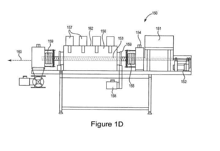
Figure 1D is a diagram illustrating a reaction chamber system 150 for
producing
fuel from organic-carbon-containing feedstock in accordance with embodiments
of the
invention. The system 150 includes an input hopper (also referred to as a load
hopper)
151 configured to allow introduction of the feedstock material into the system
150. A
gearmotor auger drive 152 provides a drive system for the auger 153 that
transports the
feedstock through the system 150. As the feedstock is compressed in the load
hopper 151,
air is extracted through the atmosphere outlet 154. A seal 155 isolates the
load hopper 151
from the reaction chamber 156 to maintain a level of vacuum. The reaction
chamber 156
includes walls of a microwave-transparent material. One or more stationary
microwave
heads 157 are positioned at the walls of the reaction chamber 156. In
addition, the system
150 includes one or more rotating microwave heads 158. In one implementation,
each
rotating microwave head is located at a fixed position with respect the
longitudinal axis
160 of the reaction chamber 156. The rotating microwave head is mounted on a
slipring
bearing 159 which allows the microwave head 158 to rotate around the reaction
chamber
156. A microwave reflective enclosure 162 encompasses the reaction chamber
156. In
some implementations the rotating microwave head(s) 158 may rotate around the
longitudinal axis 160 of the reaction chamber 156 as well as moving back and
forth along
the longitudinal axis 160. The system 150 includes a seal at the exit of the
reaction
chamber 156 to maintain the reaction chamber vacuum.
Figure 2A is a block diagram of a system 200 that uses one or more of the
reaction
chamber systems 100 illustrated in Figures lA and 1B. The reaction chamber
systems
220, 230 may be arranged and/or operated in series or in a parallel
configuration. The
extraction process 220 and the reaction process 230 depicted in Figures 2A and
2B are
illustrated as occurring in two separate reaction chambers, e.g., that operate
at different
temperatures. Alternatively, the extraction process and the reaction process
may be
implemented in a single reaction chamber with two separate zones, e.g., two
separate
temperature zones.
18
CA 02917612 2016-01-06
WO 2015/069395
PCT/US2014/058850
In the system 200 of Figure 2, one or both of the water/air extraction
subsystem
220 and the reaction subsystem 230 may be similar to the reaction chamber
system 100 of
Figures 1A and 1B. Organic-carbon-containing feedstock, such as, for example,
one or
more of manure, wood chips, plant-based cellulose, tire crumbs, municipal
solid waste,
plastic, crude oil, peat and coal, enters the system through a hopper 211, and
traverses an
airlock 212 to enter a feedstock preparation module 213. If needed, a
catalyst, such as
zeolite, and/or other additives that enhance the reaction process, for example
to adjust the
pH, may be introduced into the system 200 through the input hopper 211 and/or
the entry
ports (shown in Figure 1B). In the feedstock preparation module 213, the
feedstock
material is shredded to a predetermined particle size that may be dependent on
the
properties of the feedstock, such as the purity, density, and/or chemical
composition of the
feedstock. If used, the catalyst may be added at the time that the feedstock
is being
prepared so that the catalyst is evenly dispersed within the feedstock
material before
entering the reaction chamber 231. In general, the less uniform the feedstock,
the smaller
the particle size needed to provide efficient reaction.
After the initial feedstock preparation stage, the shredded and mixed
feedstock is
transported by a transport mechanism 215 into the extraction chamber 221 of
the next
stage of the process. The air/water extraction subsystem 220, which performs
the optional
processes of water and/or air extraction prior to the reaction process
includes a
heating/radiation module 222 comprising at least a magnetron 223 configured to
generate
microwaves 226 that may be mounted on a rotational or stationary mechanism
227. If
mounted on a rotational mechanism, the mechanism rotates the magnetron 223
either
partially or fully around the extraction chamber 221 as the microwaves 226 are
directed
through the wall 224 of the extraction chamber 221 and into the extraction
cavity 225
impinging on and heating the feedstock therein. In some embodiments, the
heating
module 222 may utilize only one magnetron 223 or only two or more magnetrons
without
using other heat/radiation sources.
In some embodiments, the heating/radiation module 222 may utilize the
magnetron
223 in addition to other heat sources, such as heat sources that rely on
thermal conduction
through the wall of the reaction chamber, e.g., flame, steam, electrical
resistive heating,
recycled heat from the process, and/or other heat sources. During the air
and/or water
19
CA 02917612 2016-01-06
WO 2015/069395
PCT/US2014/058850
extraction process, the feedstock may be heated to at least 100 C, the boiling
point of
water, to remove excess water from the feedstock. The excess water (e.g., in
the form of
steam) and/or other substances may exit the extraction chamber 221 via one or
more exit
ports. Additives to the feedstock, such as inert and/or reactive gases
including hydrogen
and/or nitrogen, may be introduced via one or more input ports into the
extraction chamber
221 of the water/air extraction process. In addition to being heated and
irradiated by
microwaves, the feedstock may also be subjected to a pressurized atmosphere
and/or a
vacuum atmosphere and/or may be mechanically compressed to remove air from the
extraction chamber 221.
After the optional air and/or water extraction process, the transport
mechanism 215
moves the feedstock to the next processing stage 230 which involves the
reaction process,
e.g., thermal depolymerization, of the feedstock. After the feedstock/catalyst
mixture
enters the reaction chamber 231 surrounded by the microwave reflecting
enclosure 238,
the mixture is heated to a temperature that is sufficient to facilitate the
desired reaction.
For example a temperature of in a range of about 200 C to about 350 C is used
to crack the
hydrocarbons in the feedstock into shorter chains to produce pyrolysis oil
through
depolymerization. In addition to being heated, the feedstock may also be
subjected to a
pressurized atmosphere or a vacuum atmosphere, and/or may be mechanically
compressed
in the reaction chamber 231.
In some embodiments, heating/radiation in the reaction chamber 231 is
accomplished using a magnetron 233 emitting microwaves 236. The magnetron 233
may
rotate relative to the reaction chamber 231. As previously described in
connection with
the water extraction stage 220, the rotating magnetron 233 may be supported by
rotational
mechanism 237, such as a cage or drum. The rotational mechanism 237 allows
relative
rotational motion between the magnetron 233 and the reaction chamber 231. For
example,
the magnetron 233 may rotate completely around the reaction chamber 231 or the
rotation
of the magnetron 233 may proceed back and forth along an arc that follows the
circumference of the reaction chamber 231. The rotating magnetron heating
system 233
may be supplemented using a stationary magnetron, and/or other conventional
heat
sources such as a flame or electrical resistive heating. Rotating the
magnetron 233
provides more even heating/radiation of the feedstock material and catalyst
within the
CA 02917612 2016-01-06
WO 2015/069395
PCT/US2014/058850
reaction cavity 235 and enhances the heating properties over that of
stationary heat
sources.
The cracked hydrocarbons vaporize and are collected in a condenser 241 and
liquefy into pyrolysis oil and then are sent to the distiller 240 to produce
products such as
a diesel fuel or a cleaner pyrolysis oil composition, while heavier, longer
chain
hydrocarbon molecules such as tars and char particulates may be recycled back
to the
reaction chamber. In some implementations, distillation may not be necessary,
and the
fuel product only needs to be filtered and used as pyrolysis oil.
In some configurations, it is desirable to control the processes of the
reaction to
allow a higher efficiency of fuel extraction from the feedstock. Figure 2B is
a block
diagram of a system 205 that includes the system components described in
connection
with Figure 2A along with a feedback control system 250. The illustrated
feedback
control system 250 includes a controller 251 and one or more sensors 252, 253,
254 which
may be configured to sense parameters at various stages during the process.
The feedback
control system 250 may include sensors 252 at the feedstock preparation stage
which are
configured to sense parameters of the feedstock and/or feedstock preparation
process. For
example, the sensors 252, may sense the chemical composition of the feedstock,
density,
moisture content, particle size, energy content or other feedstock parameters.
The sensors
252 may additionally or alternatively sense the conditions within the
feedstock preparation
chamber, e.g., flow, pressure, temperature, humidity, composition of the gases
present in
the chamber, etc. The sensors 252 develop signals 255a which are input to the
controller
electronics 251 where they are analyzed to determine the condition of the
feedstock and/or
the feedstock preparation process. In response to the sensed signals 255a, the
controller
251 develops feedback signals 255b which control the operation of the
feedstock
preparation module 213. For example, in some implementations, the controller
251 may
control the feedstock preparation module 213 to continue to shred and/or grind
the
feedstock material until a predetermined particle size and/or a predetermined
particle size
variation is detected. In another example, based on the sensed chemical
composition of
the feedstock, the controller 251 may cause a greater or lesser amount of
catalyst to be
mixed with the feedstock or may cause different types of catalyst to be mixed
with the
feedstock.
21
CA 02917612 2016-01-06
WO 2015/069395
PCT/US2014/058850
The control system 250 may also develop feedback signals 256b, 257b to control
the operation of the water extraction module 220 and/or the reaction module
230,
respectively, based on sensed signals 256a, 257a. For example, the sensors
253, 254 may
sense the temperature of the water extraction and/or reaction processes and
the controller
251 may develop feedback signals 256b, 257b to control the operation of the
heating/radiation systems 222, 232, e.g., power, frequency, pulse width,
rotational or
translational velocity, etc. of one or both of the magnetrons 223, 233. The
controller 251
may develop feedback signals to the magnetrons to control the amount of
radiation
impinging on the feedstock so that the feedstock will not be over-cooked or
under-cooked
and development of hot spots will be avoided. The controller 250 may control
the
injection of various substances into one or both of the extraction chamber
and/or the
reaction chamber 221, 231 through the entry ports to control the processes
taking place
within the chambers 221, 231. Char, the residue of the depleted feedstock, is
sent to a
storage unit. In some embodiments, the controller 250 may be used to control
conditions
that beneficially affect the properties of the pyrolysis oil where specific
properties are
desired beyond that resulting just from the feedstock choice. After the
distillation stage,
the heavy hydrocarbons may be recycled back into the reaction chamber and the
lighter
hydrocarbons may be sent on to a polymerization stage or further distillation
stage.
The reaction chambers may be made of quartz, glass, ceramic, plastic, and/or
any
other suitable material that is substantially transparent to microwaves in the
frequency and
energy range of the reaction processes. In some configurations, the
heating/radiation
systems described herein may include one or more magnetrons that rotate
relative to the
reaction chamber. In some embodiments, the magnetrons may be multiple and/or
may be
stationary. Figure 3A illustrates system 300 which includes multiple
stationary
magnetrons 311 arranged on a drum 312 that acts as a Faraday cage and is
disposed
outside a cylindrical reaction chamber 313 having one or more microwave-
transparent
walls. In system 300, the drum is made of a material that is microwave opaque,
such as,
for example, metal, so as to cause the microwaves in the reaction chamber 313
to reflect
back and forth through the feedstock, thus more efficiently being used to
convert the
feedstock into pyrolysis oil and char. The operation of the magnetrons may be
continuous,
or may be pulsed, e.g., in a multiplexed pattern. In some embodiments (Figure
3B), the
22
CA 02917612 2016-01-06
WO 2015/069395
PCT/US2014/058850
drum 313 supporting the magnetrons 311 may be rotated 330 around the
longitudinal axis
350 of the reaction chamber 312 and/or the reaction chamber 312 may be rotated
320
around its longitudinal axis 350.
A feedstock transport mechanism may be disposed within the reaction chamber.
For example, as illustrated in Figure 3C, the feedstock transport mechanism
may comprise
one or more baffles 361 that are configured to move the feedstock through the
reaction
chamber 360 as the reaction chamber rotates. The baffles 361 may be mounted to
the
walls of the reaction chamber 360 and/or may be otherwise installed within the
reaction
chamber to provide movement of feedstock within and through the reaction
chamber 360,
e.g., longitudinally through the reaction chamber.
In some embodiments, illustrated in Figure 4, one or more secondary heat
sources
450, such as a flame, steam, and/or electric resistive heating, or recycled
heat, may be used
in addition to magnetrons 416 which are stationary, or are supported on a
mechanism 417
that rotates around the circumference of the reaction chamber 420 enclosed in
a
microwave-reflecting Faraday cage 421. In some configurations, the magnetrons
416 may
not make a complete revolution around the reaction chamber 420, but may rotate
back and
forth 419 along an arc that follows the circumference of the reaction chamber
420.
Various configurations are possible as long as the feedstock is exposed to
substantially
uniform heat throughout the mass of the feedstock particles to form char
having pore
density, distribution, and variance in size and distribution as described
above for char of
the invention.
Movement of the one or more magnetrons relative to the reaction chamber may
also include motion that moves the magnetron along the longitudinal axis of
the reaction
chamber, as illustrated in Figure 5. Figure 5 illustrates a reaction chamber
510 and a cage
520 that supports a magnetron 530. The cage 520 and magnetron 530 may be moved
540
back and forth along the longitudinal axis 550 of the reaction chamber 510 and
over a
metal microwave-reflecting Faraday cage 515 enclosing the reaction chamber
510. In
some implementations, in addition to and/or concurrent with the motion 540 of
the cage
520 and magnetron 530 along the longitudinal axis 550, the cage 520, and
magnetron 530
may be rotated 560 around the longitudinal axis 550.
23
CA 02917612 2016-01-06
WO 2015/069395
PCT/US2014/058850
Figure 6 is a flow chart illustrating a process for producing petroleum
equivalent
pyrolysis oil from an organic-carbon-containing feedstock in accordance with
embodiments of the invention. An organic-carbon-containing feedstock, such as
biomass,
municipal solid waste, plant material, wood chips, and the like is input 610
to a reaction
chamber having walls that are substantially transparent to microwaves used to
heat and/or
irradiate the feedstock. The feedstock may be a solid or a suspension that
contains solid
elements. The heating and/or radiation occur by directing 620 the microwave
energy
through the walls of the reaction chamber so that it impinges on the feedstock
disposed
within the reaction chamber. The feedstock is heated/irradiated 630 by the
microwaves,
optionally in the presence of a catalyst, until reaction of the organic-carbon-
containing
molecules occurs to produce the desirable end liquid fuel product. The
pyrolysis oil
product created by the reaction processes is collected 640.
Various modifications and additions can be made to the preferred embodiments
discussed hereinabove without departing from the scope of the present
invention.
Accordingly, the scope of the present invention should not be limited by the
particular
embodiments described above, but should be defined only by the claims set
forth below
and equivalents thereof.
24