Note: Descriptions are shown in the official language in which they were submitted.
CA 2917678 2017-05-15
DUCT INTERFACE FOR CHILLED BEAM
TECHNICAL FIELD
[0001] The present disclosure relates generally to
heating, ventilation and air conditioning (HVAC) systems, and
more specifically to a duct interface for a chilled beam
system that facilitates field installation.
BACKGROUND OF THE INVENTION
[0002] A chilled beam is an item of HVAC equipment that is
used to provide cooled air to a space. Chilled beams can be
installed in a recessed configuration, where the chilled beam
is flush with ceiling tiles.
SUMMARY OF THE INVENTION
[0003] A device for connecting a chilled beam to a duct is
disclosed that includes a cuboid structure having a first
side, a second side, a third side and a fourth side, and where
the fourth side has a duct portal that can be readily
connected to field-run duct work. The device also has a top
surface and a bottom surface, where the bottom surface further
has a circular chilled beam interface that allows a mating
circular interface on the chilled beam to be rotatably coupled
to the device, so as to facilitate connecting the chilled
beam to the duct.
1
CA 2917678 2017-05-15
[0004] Accordingly, then, in one aspect, there is provided
a duct interface for a chilled beam, the chilled beam having
an exterior housing and a circular interface assembly
extending from the exterior housing, the duct interface
comprising: a first side; a second side; a third side; a
fourth side having a duct portal; a top surface; and a bottom
surface having a circular chilled beam interface extending
into the bottom surface and adapted to interlock with the
interface assembly of the chilled beam.
[0005] In accordance with another aspect, there is
provided a chilled beam comprising: an exterior housing; an
interface assembly extending outward from a top surface of
the exterior housing, the interface assembly configured to
rotatably interface with a duct interface; one or more vents
extending from the interface assembly to a bottom surface of
the exterior housing; a heat exchanger disposed in the vent;
and a lighting fixture disposed within the exterior housing.
[0006] In accordance with a further aspect, there is
provided a heating, ventilation and air conditioning system
comprising: a chilled beam comprising: an exterior housing;
an interface assembly extending outward from a top surface of
the exterior housing, the interface assembly configured to
rotatably interface with a duct interface; one or more vents
extending from the interface assembly to a bottom surface of
the exterior housing; a heat exchanger disposed in the vent;
and a lighting fixture disposed within the exterior housing;
wherein the duct interface is clearance fit with the interface
assembly; the duct interface comprising: a first side; a
second side; a third side; a fourth side having a duct portal;
a top surface; and a bottom surface having a circular chilled
2
CA 2917678 2017-05-15
beam interface extending into the bottom surface and adapted
to interlock with the interface assembly.
[0007] Other
systems, methods, features, and advantages of
the present disclosure will be or become apparent to one with
skill in the art upon examination of the following drawings
and detailed description. It is
intended that all such
additional systems, methods, features, and advantages be
included within this description, be within the scope of the
present disclosure, and be protected by the accompanying
claims.
BRIEF DESCRIPTION OF THE SEVERAL VIEWS OF THE DRAWINGS
[0008] Aspects
of the disclosure can be better understood
with reference to the following drawings. The components in
the drawings are not necessarily to scale, emphasis instead
being placed upon clearly illustrating the principles of the
present disclosure. Moreover, in
the drawings, like
reference numerals designate corresponding parts throughout
the several views, and in which:
[0009] FIGURE 1
is a side view of a system for providing
a duct interface for a chilled beam in accordance with an
exemplary embodiment of the present disclosure;
[0010] FIGURE 2 is an overhead view of a system for
providing a duct interface for a chilled beam in accordance
with an exemplary embodiment of the present disclosure;
3
CA 2917678 2017-05-15
[0011] FIGURE 3 is a diagram showing parallel installation
of chilled beams on a duct in accordance with an exemplary
embodiment of the present disclosure;
[0012] FIGURE 4 is a diagram showing series installation
of chilled beams on a duct in accordance with an exemplary
embodiment of the present disclosure;
[0013] FIGURE 5 is a diagram showing a side view of a
chilled beam, in accordance with an exemplary embodiment of
the present disclosure;
[0014] FIGURE 6 is a diagram showing a top view of a
chilled beam, in accordance with an exemplary embodiment of
the present disclosure; and
[0015] FIGURE 7 is a diagram showing an isometric view of
a chilled beam, in accordance with an exemplary embodiment of
the present disclosure.
DETAILED DESCRIPTION OF THE INVENTION
[0016] In the description that follows, like parts are
marked throughout the specification and drawings with the
same reference numerals. The drawing figures might not be to
scale and certain components can be shown in generalized or
schematic form and identified by commercial designations in
the interest of clarity and conciseness.
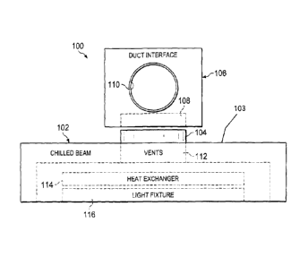
[0017] FIGURE 1 is a side view of a system 100 for
providing a duct interface for a chilled beam in accordance
with an exemplary embodiment of the present disclosure.
System 100 includes chilled beam 102, which has an exterior
housing 103 that includes interface assembly 104. Interface
assembly 104 is a circular aperture on top of chilled beam
102 that extends from the top surface of chilled beam 102.
System 100 also includes duct interface 106, which includes
4
CA 02917678 2016-01-14
mating assembly 108.
Mating assembly 108 is a circular
aperture that extends into the bottom surface of duct
interface 106 and that interlocks with interface assembly 104
of chilled beam 102. Alternatively, interface assembly 104
of chilled beam 102 can extend into chilled beam 102 and
mating assembly 108 of duct interface 106 can extend outward
from the bottom surface of duct interface 106, or other
suitable interfaces can be used.
[0018] Duct
interface 106 also includes duct portal 110,
which extends outward from a side surface of duct interface
106 and is configured to interface with a duct. In
one
exemplary embodiment, duct portal 110 is circular, but can
alternatively be square, rectangular or other suitable
dimensions in accordance with the associated duct that duct
interface 106 is used with. Likewise, duct portal 110 can
extend into the side surface of duct interface 106 where
suitable, provided that the associated duct can extend into
duct interface 106.
[0019]
Chilled beam 102 and duct interface 106 can be made
from metal, plastic, a combination of metal and plastic, or
other suitable materials or combinations of materials.
Interface assembly 104 is clearance fit outside or inside of
mating assembly 108, and can rotate 360 degrees or other
suitable amounts.
[0020] Inside of
chilled beam 102, vents 112 extend
downward from interface assembly 104 and carry outside or
mixed outside and recirculated air from interface assembly
104 past heat exchanger 114, which can be a water-cooled heat
exchanger or other suitable devices. In
addition, light
fixture 116 is disposed within chilled beam 100, and vents
112 are routed around light fixture 116. Although exemplary
vent 112, heat exchanger 114 and light fixture 116 structures
5
CA 2917678 2017-05-15
have been shown, distributed vents, adjustable light
fixtures, radiant heaters or other suitable vent, heating and
cooling or lighting structures or devices can also or
alternatively be used.
[0021] FIGURE 2 is
an overhead view of a system 200 for
providing a duct interface for a chilled beam in accordance
with an exemplary embodiment of the present disclosure. In
this overhead view, the circular perimeter of interface
assembly 104 and mating assembly 108 can be seen, in addition
to the configuration of duct portal 110.
[0022] In
operation, chilled beam 102 is typically
installed in a desired location, such as in a recessed
location in a ceiling or other suitable structure. Duct
interface 106 can then be installed on chilled beam 102, and
can be rotated in a suitable direction so that duct portal
110 is directed towards a duct structure. Additional ductwork
can then be more readily installed to connect the duct
structure to duct interface 106. In this
manner, chilled
beam 102 can be installed in parallel with duct work
installation without the risk that the chilled beam or duct
installation work will need to be redone, which facilitates
building construction activities.
[0023] FIGURE 3 is a diagram 300 showing parallel
installation of chilled beams on a duct in accordance with an
exemplary embodiment of the present disclosure. Diagram 300
includes main duct 302, with three parallel duct sections
304, 306 and 308 that are used to connect main duct 302 with
duct interfaces 310, 312 and 314, respectively. Duct
interfaces 310, 312 and 314 are then used to connect duct
sections 304, 306 and 308, respectively, to chilled beams
316, 318 and 320, respectively.
6
CA 2917678 2017-05-15
[0024] During
construction, main duct 302 may be installed
first, and parallel duct sections 304, 306 and 308 may be
installed later, after chilled beams 316, 318 and 320 have
been installed. Alternatively, parallel duct sections 304,
306 and 308 may be installed before chilled beams 316, 318
and 320 are installed, such that any misalignment of parallel
duct sections 304, 306 and 308 with chilled beams 316, 318
and 320 can result in the need for expensive and time
consuming rework. Such
misalignment of chilled beams 316,
318 and 320 can be readily accommodated by rotating duct
interfaces 310, 312 and 314, respectively, to align with duct
sections 304, 306 and 308, respectively. In this
manner,
rework can be avoided, and the installation of parallel duct
sections 304, 306 and 308 and chilled beams 316, 318 and 320
can be facilitated.
[0025] FIGURE 4 is a diagram 400 showing series
installation of chilled beams on a duct in accordance with an
exemplary embodiment of the present disclosure. Duct segment
402 connects to duct interface 408, which has opposing first
and second duct portals. Likewise, duct segment 404 connects
to duct interface 408 and duct interface 410, which also has
opposing first and second duct portals. Finally, duct segment
406 connects to duct interface 410 and duct interface 412,
which has only a single duct portal. Because duct interfaces
408, 410 and 412 can rotate on top of chilled beams 414, 416
and 418, respectively, the installation and alignment of duct
segments 402, 404 and 406 is simplified, and can readily
account for even significant deviations from designed
locations of chilled beams 414, 416 and 418.
[0026] FIGURE 5 is
a diagram 500 showing a side view of a
chilled beam 504, in accordance with an exemplary embodiment
of the present disclosure. A duct interface 502 is disposed
7
CA 2917678 2017-05-15
on top of chilled beam 504, and includes duct portal 506 and
interface assembly 508. As previously discussed, duct portal
506 and interface assembly 508 can be configured as suitable
to Interface with a duct and chilled beam 504, respectively,
and do not need to extend outwards from duct interface 502 as
shown, as long as they allow duct interface to be rotated on
top of chilled beam 504, so as to be readily interfaced with
the duct.
[0027] Chilled
beam 504 includes perimeter 510, which
interfaces with the ceiling structure. As
previously
discussed, because chilled beam 504 is installed in this
manner, the alignment of chilled beam 504 might vary from a
designed alignment by more than an allowable tolerance for
the installation of the ductwork, such that duct interface
502 can be used to compensate for such lack of alignment.
[0028] FIGURE 6
is a diagram 600 showing a top view of a
chilled beam, in accordance with an exemplary embodiment of
the present disclosure. Duct interface 602 is disposed on
the top surface 606 of the chilled beam, and duct portal 604
extends outward from duct interface 602 to interface with a
duct (not explicitly shown). Perimeter 608 of the chilled
beam interfaces with adjacent ceiling structures (not
explicitly shown), such as ceiling tiles, and is aligned with
those ceiling structures.
[0029] FIGURE 7 is a
diagram 700 showing an isometric view
of a chilled beam, in accordance with an exemplary embodiment
of the present disclosure. The chilled beam includes grates
706 and space 704 for a lighting fixture (not explicitly
shown), which can be field-installed into space 704. Duct
interface 702 is shown on top of the chilled beam.
[0030] Although
chilled beams are shown herein, other
suitable HVAC components can also or alternatively be used
8
CA 02917678 2016-01-14
with the duct interface and duct arrangements disclosed
herein. For example, passive duct components, lighted duct
components, air handling units, vents, blowers, fans, heat
exchangers, chillers or other suitable HVAC components can
also or alternatively be used.
[0031] It
should be emphasized that the above-described
embodiments are merely examples of possible implementations.
Many variations and modifications may be made to the above-
described embodiments without departing from the principles
of the present disclosure. All such
modifications and
variations are intended to be included herein within the scope
of this disclosure and protected by the following claims.
9