Note: Descriptions are shown in the official language in which they were submitted.
CA 2917749 2017-04-11
81793228
1
DEVICE FOR REGULATING A BURNER SYSTEM
CROSS-REFERENCE TO RELATED APPLICATIONS
This application claims priority to EP Application No.
15151600.2 filed January 19, 2015.
TECHNICAL FIELD
The present disclosure relates to regulating curves, as are used
for example in conjunction with ionization electrodes in burner
systems, for example in gas burners. In particular the present
disclosure relates to the correction of such regulating curves,
taking into account the ageing and/or drift of a sensor signal.
BACKGROUND
In burner systems the air/fuel ratio during combustion is able
to be established on the basis of an ionization current by an
ionization electrode. First of all an AC voltage is applied to
the ionization electrode. Because of the rectifier effect of a
flame, an ionization curre= flows as a DC current in only one
direction.
In regulating curves for ionization electrodes the ionization
current detected at the ionization electrode is plotted against
the rotational speed of the fan of a gas burner. The ionization
current is typically measured in microamperes. The rotational
speed of the fan of a gas burner is typically measured in
revolutions per minute. The rotational speed of the fan of a gas
burner is at the same time a measure for the air volume flow
rate and for the power of the burner system, i.e. for a quantity
CA 2917749 2017-04-11
81793228
2
of heat per unit of time.
Entered along such a regulating curve is a plurality of test
points. Initially these test points can be recorded under
laboratory conditions as part of testing. The recorded values
are stored and taken into account in (electronic) control.
Ionization electrodes are subject to ageing during operation.
This ageing is caused by deposits and/or accumulation of layers
during the operation of a burner system. In particular a layer
of oxide, the thickness of which changes over the hours of
operation, can form on the surface of an ionization electrode.
As a result of the ageing of an ionization electrode, a drift of
the ionization current occurs. Thus a regulating curve recorded
under laboratory conditions requires correction from time to
time, at the latest after 1000 to 3000 hours of operation.
A regulation device with correction of the regulating curve of
an ionization electrode is disclosed in EP2466204B1. The
regulating curve is corrected here in three steps. First of all
the regulation device performs regulation operation.
Subsequently the regulation device controls or regulates the
actuators of the burner system to a changed supply ratio. In
particular the speed of the fan of a burner system is changed.
By controlling the actuators the regulation device sets an air
volume flow rate of the burner system.
The changed supply ratio in this case lies above the
stoichiometric value of the air-fuel ratio of 1. Preferably the
air-fuel ratio is reduced by 0.1 or by 0.06 to values greater
CA 2917749 2017-04-11
81793228
3
than or equal to 1.05. In a third step a new required value is
computed from the ionization signal detected in such cases and
from stored data.
However the correction of the regulating curve requires that the
heat created during the duration of the tests can also he
dissipated to consumers, such as heating or process water.
Otherwise the amount of heat created during the test is higher
than the amount of heat dissipated. As a result the temperature
in the system increases and the temperature controller of the
system switches the burner off. The test on a specific air
volume flow rate cannot be completed in this case.
This problem becomes even more acute because a little time is
needed during a test run to obtain stable values. Another
complicating factor Is that the duration of a test run can
generally not just be shortened arbitrarily.
SUMMARY
One embodiment provides a device for regulating a burner system
with at least one burner, and with at least one ionization
electrode, which is disposed so that, when the burner system is
operating, it lies in the area of a flame of the at least one
burner, wherein the regulation device is embodied, on the basis
of the at least one ionization electrode, to record an
ionization current, wherein the regulation device is embodied to
set an air volume flow rate of the burner system, taking into
account the ionization current, wherein the regulation device
comprises a memory and is embodied to store pairs consisting of
air volume flow rate of the burner system .and ionization
CA 2917749 2017-04-11
81793228
4
current, wherein the regulation device is embodied to form a
difference between the reciprocal value of a first ionization
current and a first air volume flow rate and a reciprocal value
of a second ionization current, which was recorded at a point in
time before the first ionization current and belongs to the
first air volume flow rate or essentially belongs to the first
air volume flow rate, wherein the regulation device is embodied,
as the sum of this difference and of the reciprocal value of a
further ionization current, to calculate the reciprocal value
and the value of a displaced ionization current, wherein the
further ionization current and the displaced ionization current
belong to a second air volume flow rate of the burner system,
which is different from the first air volume flow rate of the
burner system, wherein the regulation device is embodied to
filter the reciprocal value or the value of the displaced
ionization current using a filter constant on the reciprocal
value or value of a historical ionization current, which was
recorded at a point in time before first ionization current and
belongs to the second air volume flow rate or essentially
belongs to the second air volume flow rate, so that, as result
of the filtering, a filtered ionization current and its
reciprocal value are calculated.
In a further embodiment, the regulation device is additionally
embodied to calculate a second difference from a reciprocal
value of the filtered ionization current and from a reciprocal
value of the further ionization current.
In a further embodiment, the regulation device is additionally
embodied to add the second difference to the reciprocal value of
CA 2917749 2017-04-11
81793228
a third ionization current and to obtain from said addition a
displaced third ionization current, wherein the third ionization
current was recorded at a point in time before first ionization
current and belongs to the second air volume flow rate of the
burner system.
In a further embodiment, the regulation device is additionally
embodied, to join together pairs consisting of air volume flow
rate of the burner system and ionization current into a
regulating curve and to store them.
In a further embodiment, the regulation device is additionally
embodied, to compute and/or to store the displaced third
ionization current as part of a corrected regulating curve
and/or to compute and/or to store from this ionization current,
the correction, especially the deviation, from the original
regulating curve.
In a further embodiment, the second ionization current was
recorded under laboratory conditions at a new or little-aged
ionization electrode.
In a further embodiment, the further ionization current was
recorded under laboratory conditions at a new or little-aged
ionization electrode.
In a further embodiment, the historical ionization current was
recorded at a point in time after the second ionization current.
In a further embodiment, the value or the reciprocal value of
CA 2917749 2017-04-11
81793228
6
the displaced ionization current are filtered on the value or
reciprocal value of a historical ionization current, in that the
value or reciprocal value of the displaced ionization current
are reduced by a percentage and the value or the reciprocal
value of the historical ionization current are increased by the
same percentage.
In a further embodiment',' the regulation device is embodied, on
the basis of the at least one ionization electrode, to record an
ionization current and the recording of the ionization current
comprises a number of individual measurements of ionization
currents.
In a further embodiment, the regulation device is embodied,
during operation, starting from the current air volume flow rate
of the burner system, to select a best fitting test point of the
regulating curve and to record at this test point a pair
consisting of ionization current and air volume flow rate and to
defer the recording of pairs consisting of ionization current
and air volume flow rate to other test points or the regulating
. curve.
. In a further embodiment, the regulation device is embodied to
form a difference between the reciprocal value of a first
ionization current for a first air volume flow rate and a
= reciprocal value of a second ionization current, which was
recorded at a point in time before the first ionization current,
and belongs to the first air volume flow rate or essentially
belongs to the first air volume flow rate, and wherein the
formation of the difference only occurs for the first time after
= CA 2917749 2017-04-11
81793228
7
an hour or after two hours or after five hours or after ten
hours or after 20 hours or after one day or after two days or
after 5 days or after 10 or after 20 days.
In a further embodiment, the regulation device is embodied, on
the basis of the at least one ionization electrode, to
repeatedly record ionization currents, and the regulation device
is embodied to repeatedly form a difference between the
reciprocal value of a first ionization current for a first air
volume flow rate and a reciprocal value of a second ionization
current which was recorded at a point in time before the first
ionization current, and belongs to the first air volume flow
rate or essentially belongs to the first air volume flow rate,
and wherein the time intervals between the formation of the
differences depend on the differences between the ionization
currents recorded in each case.
Another embodiment provides a method for regulating a burner
system with at least one burner, with at least one memory, with
at least one ionization electrode, which is disposed such that,
during operation of the burner system, it lies in the area of a
flame of the at least one burner, the method comprising the
steps of recording of an ionization current on the basis of the
at least one ionization electrode, setting an air volume flow
rate of the burner system, taking into account the ionization
current, storage of pairs consisting of air volume flow rate of
the burner system and ionization current, forming a difference
between the reciprocal value of a first ionization current for a
first air volume flow rate and a reciprocal value of a second
ionization current, which was recorded at a point in time before
= CA 2917749 2017-04-11
81793228
8
the first ionization current, and belongs to the first air
volume flow rate or essentially belongs to the first air volume
flow rate, calculating the reciprocal value and the value of a
displaced ionization current as the sum of this difference and
the reciprocal value of a further ionization current, wherein
the further ionization current and the displaced ionization
current belong to a second air volume flow rate of the burner
system which is different from the first air volume flow rate of
the burner system, and filtering of the reciprocal value or of
the value of the displaced ionization current, using a filter
constant on the 'reciprocal value or value of a historical
ionization current which was recorded at a point in time before
the first ionization current and belongs to the second air
volume flow rate or essentially belongs to the second air volume
flow rate, so that, as a result of the filtering, a filtered
ionization current and its reciprocal value are calculated.
In a further embodiment, the method additionally includes the
step of calculating a second difference from a reciprocal value
of the filtered ionization current and from a reciprocal value
of the further ionization current.
According to one aspect of the present invention, there is
provided a regulating device fOr regulating a burner system
having at least one burner and at least one ionization electrode
arranged to lie in an area of a flame of the at least one burner
during operation of the burner system, wherein the regulation
device is configured to: record an ionization current based on
the at least one .ionization electrode, set an air volume flow
rate of the burner system based on the ionization .current,
store, in a memory of the regulation device, pairs consisting of
= CA 2917749 2017-04-11
81793228
8a
air volume flow rate of the burner system and ionization current,
determine a difference between a reciprocal value of a first
ionization current and a first air volume flow rate and a
reciprocal value of a second ionization current which was recorded
prior to the first ionization current and which is associated with
the first air volume flow rate, calculate the reciprocal value and
the value of a displaced ionization current as the sum of the
determined difference and of the reciprocal value of a further
ionization current, wherein the further ionization current and the
displaced ionization current are associated with a second air
volume flow rate of the burner system that is different from the
first air volume flow rate of the burner system, and filter the
reciprocal value or the value of the displaced ionization current
using a filter constant on the reciprocal value or value of a
historical ionization current which was recorded prior to the first
ionization current and which is associated with the second air
volume flow rate, such that a filtered ionization current and its
reciprocal value are calculated as result of the filtering; joining
together pairs consisting of air volume flow rate of the burner
system and ionization current into a regulating curve and storing
them; regulating the burner system based on the regulating curve.
According to another aspect of the present invention, there is
provided a method for regulating a burner system with at least one
burner, at least one memory, and at least one ionization electrode
arranged to lie in an area of a flame of the at least one burner
during operation of the burner, the method comprising: recording an
ionization current based on the at least one ionization electrode,
setting an air volume flow rate of the burner system, based on the
ionization current, storing, in the at least one memory, pairs
consisting of air volume flow rate of the burner system and
ionization current, forming a difference between a reciprocal value
= CA 2917749 2017-04-11
31793228
8b
of a first ionization current for a first air volume flow rate and
a reciprocal value of a second ionization current which was
recorded prior to the first ionization current and associated with
the first air volume flow rate, calculating a reciprocal value and
a value of a displaced ionization current as the sum of the
difference and a reciprocal value of a .further ionization current,
wherein the further- ionization current and the displaced ionization
current are associated with a second air volume flow rate of the
burner system different from the first air volume flow rate of the
burner system, filtering the reciprocal value or the value of the
displaced ionization current using a filter constant on the
reciprocal value or value of a historical ionization current which
was recorded prior, to the first ionization current and which is
associated with the second air volume flow rate, such that a
filtered ionization current and its reciprocal value are calculated
as a result of the filtering joining together pairs consisting of
air volume flow rate of the burner system and ionization current
into a regulating curve and to store them; regulating the burner
system based on the regulating curve.
BRIEF DESCRIPTION OF THE DRAWINGS
Example embodiments of the invention are described below with
reference to figures, in which:
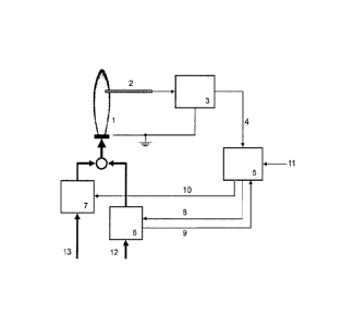
Fig. 1 schematically shows a burner system with a regulation device
that is regulated based on an ionization signal, according to an
example embodiment, and
CA 2917749 2017-04-11
81793228
9
Fig. 2 shows a regulating curve recorded under laboratory
conditions and a regulating curve deviating therefrom of an aged
ionization electrode with incomplete correction.
DETAILED DESCRIPTION
Embodiments of the present disclosure provide an improved
correction of the regulating curve of an ionization electrode.
The present disclosure is based on the knowledge that burner
conditions, and thus any corrections made to a regulating curve,
change gradually during operation. In particular the conditions
and, as a consequence, the corrections falling due along the
regulating curves, generally do not change abruptly. This makes
possible an estimation as to how a correction at a test point
affects neighboring values.
Such knowledge makes possible the correction of a regulating
curve during the operation of a burner system and for any given
air volume flow rates. The said knowledge likewise makes
possible the correction of a regulating curve in a calibration
mode or maintenance mode of a burner system. To this end, in a
first step, a number of test points are recorded, i.e.
ionization currents plotted against fan speeds or air volume
flow rates of the burner system. The result achieved by this is
that at least one test point lies close to the air volume flow
rate currently needed. Should a test run not be possible at an
existing test point, first of all the correction established for
a neighboring test point is calculated into the correction of
the existing test point. Thus the existing test point corrected
in this way is adapted to neighboring test points.
= CA 2917749 2017-04-11
81793228
Fig. 1 schematically shows a burner system, preferably a gas
burner, with an inventive regulation device and/or with the
inventive method. In normal operation the regulation operates as
fuel-air compound regulation. A burner creates a flame (1). An
ionization electrode (2) detects an ionization current. An AC
current ranging from 110 V ._ 240 V is typically present at the
ionization electrode (2). The ionization current detected by the
ionization electrode (2) means that an AC voltage applied to the
ionization electrode (2) overlays a DC voltage. This Produces a
direct current. This direct current rises with increasing
ionization of the gas in the flame area. The direct current
falls on the other hand with an increasing excess of air of the
combustion. For further processing of the signal of the
ionization electrode it is usual to use a lowpass, so that the
ionization current arises from the filtered ionization signal
(4). The DC voltage occurring results in a direct current, which
typically lies in the area of less than 150 microamperes and
frequently lies far below this value_
A device for separation of direct current and alternating
current of an ionization electrode is shown for example in
EP1154203B1, Fig. 1, and is explained, inter alia, in section 12
of the description. Reference is made here to the relevant parts
of the disclosure of EP1154203B1.
Ionization electrodes (2), as are used here, are commercially
available. KANTHALCD, e.g. APMC) or A-1 is frequently used as
material of the ionization electrodes (2)_ Electrodes made of
CA 2917749 2017-04-11
81793228
=
11
Nikrothal are also considered by the person skilled in the art.
The ionization current is amplified by a flame amplifier (3).
The flame amplifier (3) also closes the electric circuit by
connecting the flame amplifier (3) to the chassis electrode of
the burner. The ionization signal (4) processed by the flame
amplifier (3) is forwarded to a setting device (5). In normal
operation the setting device (5) uses the ionization signal (4)
as an input signal for a regulation. The ionization signal (4)
is preferably an analog electrical signal. As an alternative it
(4) can be embodied as a digital signal or as a digital variable
of two software module units.
In operation the setting device (5) reacts to an external
request signal (11), which predetermines a heat power. In
addition the regulation can be switched on and switched off on
the basis of the request signal (11). A quantity of heat and an
air volume flow rate connected therewith can be requested from a
superordinate temperature regulation circuit not shown in
FIG. 1. Furthermore such a specification can be predetermined
directly by an external consumer and/or manually, by means of a
potentiometer, for example.
It is usual to map the request signal (13) onto one of the two
actuators (6, 7) with the aid of data stored in the setting
device (5). In a preferred embodiment the request signal (11) is
mapped onto required speed values =for a fan as first actuator
(6). Subsequently the required speed values are compared with a
speed signal (9) returned by a fan (6). A speed regulator
integrated into the setting device (5) controls the fan (6) via
CA 2917749 2017-04-11
81793228
12
a first setting signal (8) to a required amount of air (12) to
be conveyed in accordance with the request signal (11). In a
specific embodiment the setting device (5) includes a rotational
speed regulation, especially a rotational speed regulation
according to proportional, integral and/or derivative
components, and forwards a setting signal to the fan (6).
According to a further embodiment the request signal (11) can be
mapped directly onto the first setting signal (8) of the fan
(6). The mapping of the request signal (11) to a fuel valve as a
first performance-managing actuator is also possible.
A second actuator (7), preferably a fuel valve, adjusts the
air-fuel ratio via the supply of fuel (13). To this end the
setting device (5) maps the predetermined request signal (11),
i.e. the speed response signal (9), to a required value of the
ionization signal (4). On the basis of the difference between
ionization signal (4) and required value of the ionization
signal (4), the fuel valve (7) is regulated via a regulation
unit contained in the setting device. In this way a change of
the ionization signal (4) via a second setting signal (10)
causes a change in the setting of the fuel valve (7). Thus the
throughflow of fuel (13) is changed. The regulation circuit is
closed, by, for a given quantity of air, a change of fuel.amount
causing a change of ionization current through the flame (1) and
through the ionization electrode (2). Connected therewith is a
change of the ionization signal (4) until such time as its
actual value is again equal to the predetermined required value.
Fig. 2 shows a regulating curve (14) as a solid curve. In Fig. 2
the ionization current in microamperes (15) is plotted against
= CA 2917749 2017-04-11
81793228
13
the air volume flow rate (16). According to a preferred
embodiment the air volume flow rate (16) corresponds to the
rotational speed of the fan (6). Such a regulating curve is used
by the setting device (5) to set the air-fuel ratio for
different request signals(11), taking in account the ionization
signal (4).
In other words the regulation device is embodied to set an air
volume flow rate (16) of the burner system, taking into account
the ionization current (15).
Current burner systems in the sense of this disclosure have
powers ranging from a few lOs of kW up to 100 kW and beyond and
the associated air volume flow rates. Normal speeds of the fan
range from a few 1000 to 10000 revolutions per minute.
Fig. 2 shows the ionization current (15) for different air
volume flow rates (16). The different values of the ionization
current (15) for different air volume flow rates (16) are first
of all recorded in the laboratory (under test conditions). From
these the regulating curve (14) is produced. In Fig. 2 recorded
pairs of values consisting of ionization current and air volume
flow rate are connected on the basis of straight, solid lines,
to form a regulating curve. The pairs of values are support
points of the regulating curve and are marked by crosses X in
Fig. 2.
The recording of the support points of a regulating curve
preferably takes place in the laboratory with a new and/or
little-aged ionization electrode (2).
CA 2917749 2017-04-11
81793228
14
The totality of these support points forms a regulating curve,
as shown in Fig. 2. To this end the regulation device is
embodied to join the support points together into a regulating
curve. According to a preferred embodiment the joining together
into a regulating curve also includes the interpolation
disclosed below. =
Accordingly the regulation device comprises a memory and is
embodied for storing pairs consisting of air volume flow rate
(16) of the burner system and ionization current (15). The
memory can for example involve random access memory (RAM), flash
memory, EPROM memory, EEPROM memory, memory registers, one or
more hard disks, one or more diskettes, other optical drives or
any computer-readable medium. This list is exemplary only. In a
preferred embodiment the memory of the regulation device is non-
volatile.
According to Fig. 2 there is linear interpolation between the
recorded values. In a further embodiment there is quadratic
interpolation between the recorded. values, i.e. as well as a
linear term, a quadratic term and/or a higher-order term is also
taken into account. According to a further embodiment there is
interpolation between the recorded values on the basis of
(cubic) splines.
In general, in addition to the recorded values of the ionization
current (15), the interpolation creates further values of the
ionization current (15). The further values of the ionization
current lie between the recorded values. They also lie between
CA 2917749 2017-04-11
81793228
1;
the correspondingly set air volume flow rates (16) of the burner
system. The ionization current for the air volume flow rate
between the recorded values is produced from the interpolation.
Like the support points of the regulating curve, the test points
are likewise established in the laboratory with a new and/or
little-aged ionization electrode. This is done with the aid of
the test sequence as disclosed in EP2466204)31. Of these test
points, the Ico values are shown in Fig. 2 as circles on the
regulating curve (14). The Igo values are shown as circles above
the regulating curve (14). Ico value and Igo value of a test point
lie at the same (or essentially the same) fan speed or at the
same (or essentially the same) air volume flow rate. The /cc
values are produced from the regulating curve as a result of the
selected air volume flow rates for the test points. They can
either be identical to a support point or can be computed
through interpolation. The Igo values are produced as a result of
the selected X change of the air-fuel ratio at the respective
test point.
It is further guaranteed in the laboratory that a requested
amount of heat or air volume flow rate (16) is also discharged.
Thus the case in which the temperature in the system rises (too
quickly or too far) is excluded in the laboratory, because the
burner, for the duration of test runs (for setting the fan
speeds, the fan-speed spacing and establishing the Igo value per
test point) creates more heat than can be dissipated. Thus it is
possible, under laboratory conditions, to establish all
(above-mentioned) values for the test points.
CA 2917749 2017-04-11
81793228
16
According to a specific embodiment 8, 16, 32 or 64 support
points for the regulating curve are recorded in the laboratory.
According to a further embodiment 5, 10, 15, 20 or 25 test
points are recorded along the regulating curve (14) under
laboratory conditions. In the event of the regulating curve
points (support points) not coinciding with the test points,
interpolation is carried out in accordance with one of the
methods given above between the recorded support points of the
regulating curve, in order to obtain the /cc values at the test
points.
The ionization electrode (2) is typically subject to ageing
during operation. The characteristics of the ionization
electrode (2) change as a result of the ageing. In other words,
the regulating curve of an aged ionization electrode (2)
deviates from that (14) of a new ionization electrode (2).
Fig. 2 shows a deviating regulating curve (17) as a dashed-line
curve. The deviating regulating curve (17) takes account of the
ageing of the ionization electrode (2). The points of this
regulating curve (17) indicated in the form of crosses are the
ionization current values at the test points corrected as a
result of the tests. =
Fig. 2 shows a special test point (18) in addition to the cross-
shaped test points. Test point (18) involves a test point at
which at least one test run must have been aborted (or could
even not be started at all). Therefore the ionization current of
this test point (18) has been recorded at a point in time before
the ionization currents of the other test points of the dashed-
.
CA 2917749 2017-04-11
81793228
17
line regulating curve (17).
In practice it is entirely possible for a number of test
sequences to have failed at the rest point (18). This can occur
for example if, at the time of one or more tests, the required
amount of heat or the required air volume flow rate (16) is not
discharged. The temperature in the system rises in such a case,
as described above, and the test run is aborted.
The dashed-line regulating curve (17) deviates upwards in the
area of the test point (18). Thus the dashed-line regulating
curve (17) and the regulating curve (14) recorded in the
laboratory are closer to each other in the area of the test
point (18) than they would otherwise be. It can be assumed from
this that the regulating curve (17) distorted by that test point
(18) does not optimally characterize the aged ionization
electrode (2).
First of all the obviously erroneous test point (18) can now be
corrected, based on the assumption that neighboring test points
change in a similar way. At a test point of the regulating
curve, let 1-130 be the recorded ionization current during a test
run under laboratory conditions and .T.B1 be the recorded
ionization current during a first test run after a few hours
operation. According to EP2466204B1 the ionization currents .T.B0
and I correspond to an enriched mixture compared to the
regulating curve, meaning that there is more fuel (13),
especially more gas, and less air (12) present. A similar
situation can be reached for example by more fuel (13) being
supplied at a constant fan speed.
CA 2917749 2017-04-11
81793228
18
Now let the test run k have failed at the erroneous test point
(18), so that no ionization Current IBI, is present. In addition,
at the neighboring point of the test points (18), let the
ionization current ineighbornk of the kth test run and the
corresponding laboratory value T
-neighborBO be known. The ionization
current ./Bi, is now calculated or estimated from the ionization
currents 'neighborBk and IneighborBo of the neighboring test points and
is called /so' below:
1 1 1 1
,
./Bkt Ineighbora IneighborBO 150
The estimation is based on the assumption that neighboring test
points are (approximately) displaced to the same extent. This
assumption is not always a good approximation. This is
especially the case if the test value differs greatly from one
test run to the next.
The test at a test point estimated through a neighbor (as above
e.g. test point (18)) is basically rectified as soon as .the
burner power or the air volume flow rate matches.
In other words, the disclosed regulation device is embodied to
form a difference between the reciprocal value of a first
ionization current inei wthorBk for a first air volume flow rate and
a reciprocal value of a second ionization current I neighborBOt which
has been recorded at a point in time-before the first ionization
current T
-neighborBk and belongs to the first air volume flow rate or
essentially belongs to the first air volume flow rate.
CA 2917749 2017-04-11
81793228
19
Let I
neighbor80 have been recorded at a point in time before first
ionization current T
- nea ghborBk r in that T
- ghborBO was recorded for
example during a test run under laboratory conditions. Test runs
under laboratory conditions typically take place as type
tests/setting (= required value/parameter establishment) and/or
routine tests and/or as factory tests during the development or
during the manufacturing of a device.
The disclosed regulation device is further embodied, as the sum
of this difference and of the reciprocal value of a further
ionization current 1)30, to calculate the reciprocal value and the
value of a displaced ionization current /Bo', wherein the further
ionization current and the displaced ionization current belong
to a second air volume flow rate of the burner system which is
different from the first air volume flow rate of the burner
system.
In order not to make the correction solely on the basis of this
estimation and since /13),/- will not be identical under all
environmental conditions with a real measured I
-Bk r IBk S
filtered with the filter constant e on the ionization current
Ip(k-1) of a preceding test run. A value for the filtered
ionization current IBk, is thus obtained.
113(k-1). e Il3kT = (1 ¨ e)
In this equation the index k relates to the current test run.
The ionization currents and air volume flow rates with the
CA 2917749 2017-04-11
81793228
indices 1 to k - 1 relate to test runs previously carried out or
to the test values computed by filtering, i.e. to historical
tests at this test point. Depending on the embodiment,
individual values of these historical test values or all
historical test values are stored in the regulation device.
In this case the value of the filter constant e can assume
values between 0 and 1, preferably between 0.2 and 0.6, further
preferably between 0.35 and C.65 or 0.5 to 0.9. The fitting is
done at a test point with the same or with essentially the same
air volume flow rate (16) of the burner system.
The person skilled in the art readily recognizes that the
aforementioned filtering can also be carried out in a similar
manner on the basis of reciprocal values and on the basis of a
filter constant e', i.e. according to
1 1 1
=, ___________________________ = e' = (1 ¨ e')
!Biz, (k-1) IBICr
The filter constants e and e' can be different from one another.
In other words the regulation device is embodied to filter the
reciprocal value or the value of the displaced ionization
current IBict using a filter constant e, e' on the reciprocal
value or value of a historical ionization current //3(k_1), which
was recorded at a point in time before the first ionization
current Ineighbor8k and which belongs to the second air volume flow
rate or essentially belongs to the second air volume flow rate,
so that as a result of the filtering, a filtered ionization
=
= CA 2917749 2017-04-11
81793228
21
current 1.5k and its reciprocal value are computed.
Let -..TR(.,1) have been recorded at a time before the first
ionization current
- ne.whborBk in that /-130,_1) has been recorded for
example during the test run in operation with the index k - 1.
The test run in operation with the index k - 1 in this case
precedes the test run in operation with the index k. Typical
time intervals between consecutive test runs lie in the range of
a few lOs of hours to a few 100 hours. But just a few hours or a
few thousand hours can also lie between consecutive test runs.
Each of these filterings hides a Markov assumption, according to
which a filtered ionization current IBk of a test point depends
on the ionization current IB(k-.2) of its immediately preceding
test point. According to a further embodiment the filtered
ionization current I. of a test point depends on ionization
currents IB(k_l) and I130,2) of two preceding test points:
= 1B(k-l) e + la(k-z) f + IBki = (1- e
The same applies for the filtering on the basis of reciprocal
ionization currents. The value of the filter constant f varies,
as does the value of the filter constant e, between 0 and 1,
preferably between 0.2 and 0.8, further preferably between 0.35
and 0.65 or between 0.5 and 0.9. The filter constants e and f
can be the same or different, depending on the embodiment. The
person skilled in the art readily recognizes that the filtering
of ionization currents on the basis of preceding test points can
also relate to more than two ionization currents of preceding
test points.
= CA 2917749 2017-04-11
81793228
22
From the computed test value IBk, the ionization current of the
regulating curve is finally corrected in accordance with the
method disclosed in EP2466204B1, for example in Fig. 2 the point
(18). The method disclosed in EP2466204B1 is based on the
knowledge that ionization currents can be corrected like
electrical (error) resistances. The corrected ionization current
ick, of the regulating curve is therefore calculated from the
reciprocal ionization currents //Ilk', VIB0 of (precisely) this
test point and from the reciprocal ionization current ///co (of
the original regulating curve and established at this point
under laboratory conditions) in accordance with
1 1 1 1
_
lck, Isk, Iso 'co
In other words the regulation device is embodied to calculate a
second difference from a reciprocal value of the filtered
ionization current /Bk, and from the reciprocal value of the
ionization current /Bo.
The regulation device is additionally embodied to add this
second difference to the reciprocal value of a third ionization
current ICU and to obtain a displaced third ionization current
ick from this, wherein the third ionization current /co was
recorded at a point in time before the first ionization current
Ineigh.borBk and belongs to the air volume flow rate of the burner
system.
Let /co be recorded in time before the first ionization current
CA 2917749 2017-04-11
81793228
23
IneghborEik, in that 1f:0 was recorded for example during a test run
under laboratory conditions. Test runs under laboratory
conditions typically take place as type tests and/or routine
tests and/or as factory tests during the development or during
the manufacturing of a device.
In accordance with a specific embodiment in this case each
individual recorded value of the ionization current /Bo, if
necessary Im and if necessary /co, is a (weighted) average value
of a number of measured values of the ionization current. In
accordance with a particular embodiment the weighting involves
an arithmetic or geometric mean. According to a further
embodiment, during the weighting n inverse ionization currents
1/1)30/, T 1/
, -1302r 1/1)303 1/IBOn are averaged to a mean ionization
current 1,30 in accordance with
1 1 1 1
Isoz .1B03 1BOn
The ionization current Ick thus established is now used as the
basis for the corrected regulating curve. In the present case
for example the ionization current is replaced at the obviously
erroneous test point (18) by the ionization current ick,
In other words the regulation device is additionally embodied to
store the displaced third ionization current as part of a
corrected regulating curve (17) and /or from this ionization
current to compute and/or to store the correction (deviation) to
the original regulating curve.
CA 2917749 2017-04-11
81793228
24
The burner system continues on the basis of the corrected
regulating curve, until the burner system once again activates
the power range or the air volume flow rate at test point (18),
i.e. modulates in the area around test point (18). In this case
an ionization current can be determined at the same test point,
so that an actual measured value is present. The burner system
then again uses a regulating curve based on measured values and
not (only) on filtered estimated values. The modulation of the
burner system in the area around the test point (18) can be
undertaken both explicitly when the burner system is started and
also during operation.
The present correction based on a filtering of the ionization
current on preceding measured values is not used during the
first hours of operation. Because of the peculiarity of a
comparatively rapid ageing of the ionization electrode (2)
during the first hours of days of operation a fitting during
this period is suppressed. Preferably a fitting is suppressed
for a period of around three days of operation. It is further
preferred for a fitting to be suppressed during an initial
operating time of one hour or of two hours or of five hours or
of ten hours or of 20 hours or of one day or of two days or of 5
days or of 10 days or of 20 days. The suppression of the fitting
produces combustion values deviating for the new state and as a
rule somewhat leaner, which can be well tolerated however.
According to a further embodiment the correction based on a
fitting is not suppressed during the first operating hours.
Instead the comparatively rapid ageing of the ionization
electrode (2) is taken into account in that test runs are first
CA 2917749 2017-04-11
8 17 93228
executed at shorter intervals. Through the use of test runs at
shorter intervals the test points move less strongly between the
test runs. Therefore, with test runs within shorter time
intervals the said method of fitting the curve to ionization
currents for preceding measured values can continue to be used.
According to a further embodiment the comparatively rapid change
of the ionization electrode (2) is established by shorter
intervals between test runs. In this case the system detects the
change of ionization current between consecutive test runs and
automatically shortens or lengthens the intervals between test
runs. The shortening or lengthening of the intervals between
consecutive test runs occurs in such cases as a function of the
change in the ionization current (i.e. as a function of the
gradient).
In other words, the regulation device is embodied, on the basis
of the at least one ionization electrode (2), to repeatedly
record ionization currents (15), and the regulation device is
embodied to repeatedly form a difference between the reciprocal
value of a first ionization current and a first air volume flow
rate (16) and a reciprocal value of a second ionization current,
which was recorded at a different time from the first ionization
current and which belongs to the first air volume flow rate (16)
or essentially belongs to the first air volume flow rate (16),
wherein the intervals between differences being formed depend on
the differences of the respective recorded ionization currents.
According to one embodiment, on the basis of the aforementioned
steps and/or formulae, not only can ionization currents which
CA 2917749 2017-04-11
81793228
= 26
belong to an aborted test run be displaced and/or fitted to
curves. Instead any given values of ionization currents on a
regulating curve can be estimated and/or filtered. This
especially includes such values of ionization currents as have
arisen through interpolation between measured values.
According to a further embodiment the correction of the
regulating curve is carried out by the best fitting test point
being selected during operation, starting from the current
burner power. As a rule the best fitting test point is that test
point which is closest to the current burner power of the
current fan speed or the current air volume flow rate. An
ionization current is then recorded at this test point. The
ionization currents at the remaining test points are recorded
subsequent to the ionization current for the best fitting test
point. The ionization currents can for example only be recorded
when the burner power or the fan speed or the air volume flow
rate is modulating in the vicinity of the respective test point.
In other words, the regulation device is preferably embodied,
during operation, starting from the current air volume flow rate
16 of the burner system, to select a best fitting test point of
the regulating curve (14 or 17) and at this test point to record
a pair consisting of ionization current 15 and air volume flow
rate 16. The recording of pairs consisting of ionization current
15 and air volume flow rate 16 at other test points of the
regulating curve (14 or 17) is deferred.
Parts of a regulation device or of a method in accordance with
the present disclosure can be realized as hardware, as a
CA 2917749 2017-04-11
81-793228
27
software module, which is executed by a processing unit, or on
the basis of a cloud computer, or on the basis of a combination
of the aforementioned options. The software may be firmware, a
hardware driver, which is executed within the operating system,
or an application program. The present disclosure thus also
relates to a computer program product containing the features of
this disclosure for executing the necessary steps. When realized
as software the functions described can be stored as one or more
commands on a computer-readable medium. A few examples of
computer-readable media include random access memory (RAM),
magnetic random access memory (MRAM), read-only memory (ROM),
flash memory, electronically-programmable ROM (EPROM),
electronically-programmable and erasable ROM (EEPROM), registers
of a processor unit, a hard disk, a removable memory unit, an
optical memory or any other suitable medium which can be
accessed by a computer or by other IT facilities and
' applications.
The above description relates to individual forms of embodiment
of the disclosure. Various modifications can be made to the
forms of embodiment without deviating from the underlying idea
and without departing from the framework of this disclosure. The
subject matter of the present disclosure is defined via its
claims. A wide variety of modifications can be made without
departing from the scope of protection of the following claims.
CA 2917749 2017-04-11
81793228
28
List of reference characters
1 Flame
2 Ionization electrode
3 Flame amplifier
4 Ionization signal
Setting device
6 First actuator
7 Second actuator
8 First setting signal
9 Rpm signal
Second setting signal
11 Request signal
12 Air
13 Fuel
14 Regulating curve recorded in the laboratory under test
conditions
Y-axis with ionization current
16 X-axis with fan speed or air volume flow rate or burner
power/power of the burner system
17 Regulating curve, taking account of the ageing of the
ionization electrode
18 Test point with aborted test run