Note: Descriptions are shown in the official language in which they were submitted.
CA 02917953 2016-01-11
WO 2015/007514 PCT/EP2014/063930
1
METHOD OF ORDER FULFILLING BY PREPARING STORAGE UNITS AT A
PICKING STATION
The invention relates to a method of order fulfilling in accordance with the
preamble of
claim 1.
When picking or compiling orders from transporting units, such as e.g.
articles or
containers, it is necessary to provide the transporting or storage units,
which are
associated with a common order, in a directed or sorted fashion. In addition,
it is
conventional to intermediately store (buffer) the transporting units of an
order, until all
of the transporting units required for the order are present. They are then
passed
together onto a collecting line which leads them e.g. to the palletization
area, picking
station, goods issue, shipment etc.
In the picking station the goods for fulfilling an order are taken from the
transporting or
storage units and placed according to the order into an order container etc.
The
storage container (often called donor) is then routed back into the racking
storage and
stored until needed for the next order.
A (high bay) racking storage facility includes a storage-entry area, via which
the goods
are supplied to and from which the Automatic Storage and Retrieval Machine
(hereafter called AS/RS) collects the goods for placement in storage, the so-
called
front-zone. In a similar manner, a retrieval area is required, at which after
retrieval
from storage the AS/RS deposit the goods which are likewise assigned to the
front-
zone. In the case of automatic picking storage facilities, picking locations
are typically
situated in the front-zone. In the front-zone, the goods are also identified
for the
inventory management system or the material flow computer.
EP 1 964 792 B1 by the present applicant discloses a method of making
transporting
units available from a storage facility on at least one collecting line. AS/RS
in each
storage racking aisle, retrieval-from-storage and outbound lines are
controlled, in such
a way as to be matched and coordinated to one another, and are loaded with
goods
that ultimately they end up on, or are discharged from, the collecting line in
a sorted
fashion.
CA 02917953 2016-01-11
WO 2015/007514 PCT/EP2014/063930
2
The control and matching are thus relatively complex and require evident
technical
work in the so-called front-zone, i.e. the area outside the actual racking, is
necessary
to achieve high trough put and sequencing.
In contrast thereto, the object of the invention is to provide a method of
order fulfilling,
which provides sorted retrieval from storage in a simpler manner and without
sortation
outside of the aisles. This reduces technical complexity and space, lowers
cost and
achieves better reliability and throughput.
This object is achieved by the method stated in claim 1.
In accordance with the invention, it has been recognized that when each lift
is directly
connected to a picking station in a picking level by the storage-entry
conveyor and the
storage-exit conveyor, it is possible to dispense with the so-called
front¨zone for
sequencing while improving performance of the lift, because the aisles are
independent from each other and tightly coupled to the picking station.
Preferably only one lift is connected to one or more picking station, as this
simplifies
the system and realizes very good throughput. Additionally two lifts in a
single aisle
may be connected to one picking station on a single level.
In the present application the picking stations can be manual operated and
either
semi- or fully automated order picking stations. A fully automated picking
station is
defined as a picking station according to the goods-to-person principle with
fully
automated unit (totes, container, trays, boxes etc.) handling, i.e. a fully
automated
supply and discharge and presentation of the product and order units. Empty
order
units and/or units with commissioning goods are automatically supplied to the
work
station. Units are placed in ergonomically optimal height on the picking
station.
Usually such a station will also incorporate means for directing, instructing
and
controlling as well as supervising the picker (e.g. pick-to-light, optical
pointing device,
IT display etc.), who will still manually pick out of product units into order
units. In
contrast a semiautomatic picking station will not have the fully automated
unit
handling just described, but will involve some manual processing of units.
CA 02917953 2016-01-11
WO 2015/007514 PCT/EP2014/063930
3
The picking stations may be orientated such that they face each other and
lifts are
located between them. It is also possible that two picking stations are
connected to
two lifts on a single level.
Additionally a picking station may have temporary shelving, e.g. for pre-
picking certain
articles
Preferably the automatic storage and retrieval device is fed by an inbound-
buffer-
conveyor and/or feeds into an outbound-buffer-conveyor, wherein the buffers
are
arranged within the racking unit. This allows for high performance due to
quick relief of
the AS/RS.
It is also preferred that the outbound-buffer feeds into the conveyor loop and
inbound-
buffer is fed by the conveyor loop, in particular in the picking level.
The conveyor loop may also contain a junction or switch as an option to
selectively
feed the inbound-buffer, so that storage units coming from the picking station
via the
storage-entry feeding line passing through the lift can be conveyed to the
inbound-
buffer, or, in other words, pass through the loop.
In a preferred embodiment the at least one lift is arranged in one of the pair
of racking
units (racks of an aisle) and is possibly of the drive-through-type, but not
limited to,
and is fed by the storage-entry feeding line and itself feeds the outbound
line of a first
conveyor loop in a first picking level, but circumnavigates around a second
lift
arranged in the other of the pair of racking units, which is also of the drive-
through-
type, but not limited to, and is fed by the storage-entry feeding line and
itself feeds the
outbound line of a second conveyor loop in a second picking level, wherein the
conveyor loop circumnavigates around the first lift in the second picking
level. This
allows for use of two picking levels that each are only coupled to one lift to
achieve
high performance.
In the non-picking levels the lift is preferably fed by an inbound-buffer and
feeds into
an outbound-buffer, wherein the buffers are arranged within the racking unit.
In accordance with a further aspect of the invention, it has been also
recognized that
CA 02917953 2016-01-11
WO 2015/007514 PCT/EP2014/063930
4
when transporting or storage units are exchanged directly between two
adjoining
storage racking units from one storage racking aisle to an adjacent storage
racking
aisle via cross conveyance locations in the storage racking units,
distribution and/or
complex sorting in the front-zone can be omitted, since the transporting units
are
already stored in a single storage rack aisle even if initially they were
stored
elsewhere. When retrieved from storage, they are simply retrieved in sequence
within
a single aisle. Therefore a direct transfer of the transporting units without
distribution
or sorting outside of the aisles can be achieved without "crossing" conveyors
and this
with a simpler and smaller technical installation with smaller space and
higher
reliability. The transporting or storage units can therefore just be retrieved
from the
respective aisle in the required sequence.
The storage is preferably a fully automated storage.
In other words, storage racking locations of abutting racking units are used
for passing
transporting or storage units from one side of the racking through to the
next, so that
the transporting units can be transferred from one racking to the next.
Therefore, cross conveyance or sorting is possible inside the racking units
themselves
and accordingly it is possible to dispense with or at least minimize "cross
conveyance"
in the front-zone.
In an expedient manner, the cross conveyance locations are provided in each
level or
any selected level of the storage racking units.
Particularly effective path-time optimization is achieved if the cross
conveyance
locations are disposed closer to inbound and outbound buffer conveyors. It is
also
possible to locate cross conveyance locations at different positions within a
level.
The cross conveyance locations can also be used as buffers, especially if they
belong
to final destination aisle of the transport or storage units, i.e. the
transporting or
storage units remain therein, until they are actually needed or retrieved.
The exchange can be effected actively or passively with regard to the AS/RS
i.e., on
the one hand the cross conveyance location can be simply a passive storage
surface,
CA 02917953 2016-01-11
WO 2015/007514 PCT/EP2014/063930
on which the AS/RS of one aisle deposits transporting or storage units (quasi
places
them into storage) and from which the AS/RS of the adjacent aisle receives
transporting units (quasi removes them from storage). For each racking storage
location or cross conveyance location this procedure can always be performed
in one
5 direction only or in both directions.
On the other hand, it is likewise possible to equip the cross conveyance
location with
corresponding conveyance technology, such as driven rollers, gravity flow
track, idler
roller, conveyor belts with or without a drive etc. The AS/RS can then deposit
the
transporting or storage units and the conveyance technology of the cross
conveyance
location performs transportation. The cross conveyance locations can also be
equipped with a push mechanism for the transporting units.
By reason of the simplicity of the cross conveyance locations it is also
possible to
subsequently retrofit or refit cross conveyance locations and to adapt
flexibly to the
level of efficiency required in the storage system.
The cross conveyance locations can thus optionally be configured for
bidirectional or
unidirectional exchange and/or for active or passive exchange.
For exchange purposes, the AS/RS can likewise place the transporting units in
normal
storage, double-depth storage or multiple-depth storage in the cross
conveyance
location. The AS/RS of one aisle can thus place the transporting or storage
units in
storage in the cross conveyance locations to such a depth that they are
already to be
assigned to the adjacent racking and can be reached "normally" by the AS/RS in
the
adjacent racking.
In addition, the load receiving means, e.g. telescopic arms, can have an
extended
range.
It is also possible to use a stacked storage of transporting or storage units.
Since the cross conveyance locations are subjected to be utilized extensively
and
reduce a damage of transport or storage unit, it is expedient if the floors of
the cross
conveyance locations can be coated to reduce friction and/or structural
reinforcement
CA 02917953 2016-01-11
WO 2015/007514 PCT/EP2014/063930
6
can be effected.
It is particularly preferable if the AS/RS are single-level racking serving
units. In
particular shuttles or satellite vehicles are preferred. Also shuttles with a
stacked
arrangement of two load handling platforms or an elevating platform are to be
used in
connection with the invention for handling several levels from a single rail.
It is thus possible in accordance with the invention to achieve a particularly
high level
of retrieval efficiency whilst fully maintaining the desired sequence of
transporting or
storage units in any aisle. This is also achieved with considerably less
technical work
than in accordance with the Prior Art.
In one option, the shuttle is decoupled from the at least one lift by an
inbound-buffer-
conveyor and/or an outbound-buffer-conveyor, wherein the buffer-conveyors are
arranged within the racks.
The outbound-buffer-conveyors and inbound-buffer-conveyors may also be located
in
a rack or alternatively outside of a rack. Alternatively the outbound-buffers
are located
in or outside of one rack of an aisle and inbound-buffers are located in or
outside the
other rack of an aisle. Further it is possible to locate the outbound-buffers
and/or
inbound-buffers in or outside of the racks of an aisle in a per level
alternating fashion,
i.e. the inbound-buffers are arranged on even levels of a rack and outbound-
buffers in
the odd levels of the same rack. Under this scenario, the units on a level
where the
outbound buffer conveyor is missing are always transferred to an adjacent
aisle via
cross conveyance locations. Likewise, on the level where the inbound buffer
conveyor is missing units from an adjacent aisle are received via cross
conveyance
locations. Obviously it is also possible to not locate buffer conveyors on
each and
every non-picking level but only every few levels.
For high performance it is preferred that outbound-buffer-conveyors and
inbound-
buffer-conveyors are located on every non-picking level.
The storage-entry conveyor and the storage-exit conveyor should preferably be
arranged in the same level, especially the picking level, i.e. the level in
which the
picking station is located. Alternatively the storage-entry conveyor and the
storage-exit
CA 02917953 2016-01-11
WO 2015/007514 PCT/EP2014/063930
7
conveyor may be arranged in different levels, so that the picking station is
supplied on
one level and units are dispatched from it on a second level.
It is also possible that each storage-entry and/or exit conveyor level has
buffer
conveyors directly feeding or fed by storage-entry and/or exit conveyors.
It is understood that where the term "transporting units" or likewise "storage
units" is
used, it is not to be interpreted as limiting, in fact other types of
transport (e.g. trays,
pallets etc.) can also be used equally effectively within the scope of the
invention. In
particular, the term "transporting units" or "storage units" also includes
totes, trays,
containers, paperboard containers, carton boxes, packaging units, i.e.
combined
individual articles, etc. and individual articles. These units can either be
donor units,
from which a picker takes articles for an order, so that these function as a
donor (often
also called product units), or these units can be order units for collecting
articles of an
order.
The transporting or storage units can be placed in storage randomly
("chaotically")
being distributed over the entire system without knowledge of the subsequent
sequence when they are retrieved. In contrast to DE 299 12 230 U1 no
restriction as
to possible modules or storage areas is required.
In particular, so-called Multishuttles are used as the single-level AS/RS.
The
Multishuttle is a system which can be used universally, is constructed in a
modular
fashion and combines storage and transportation in an integrated concept. The
Multishuttle supplements the domain of automatic small parts storage
facilities as a
high-performance, inexpensive and innovative solution. It is a rail-borne
vehicle which
operates in the racking and serves the entire storage system. The system
concept is
based upon autonomous rail-guided vehicles for container transportation which
operate inside and outside the storage system. A specific load receiving means
permits short load-change times and simultaneous loading and unloading. The
system has travel rails which are installed in each level of the storage
facility or
elevated or suspended in the pre-zone. In addition to guiding the vehicles,
they also
supply voltage thereto.
The shuttle can be used in two arrangements, a so called "captive" or
"roaming"
CA 02917953 2016-01-11
WO 2015/007514 PCT/EP2014/063930
8
arrangement. In the captive arrangement the shuttle stay in their respective
level. In
the roaming alternative the shuttle change levels as required.
Possible outbound lifts include in particular vertical conveying means. It is
favorable if
each outbound lift has one or more, in particular two, locations/positions for
the
transporting or storage units.
It is also expedient if each level of the storage racking has at least one
buffer location
for decoupling the single-level AS/RS and the outbound lift. This renders it
possible to
fully utilize the quicker single-level AS/RS and to prevent empty-running of
the lift.
Each outbound lift may be connected to several outbound lines. This improves
the
sorting options and increases the number of orders which can be processed in
parallel, or the number of stations which can be supplied.
In the simplest case, the outbound lines are formed as accumulations
conveyors.
These may include a mechanical device for accumulation, e.g. a movable stop
element.
It is also advantageous if each outbound lift has a separately driven
conveying means
for each location. In particular, it is then expedient if each outbound lift
has two
locations which are each provided with a separately driven conveying means
movable
in different directions. Therefore, the transfer of two transporting or
storage units for
each level (e.g. in a previously standing arrangement) can always be effected
simultaneously in different directions or onto different outbound buffers,
e.g. to the left
and right. In addition, the reception of the transporting units onto the lift
is preferably
controlled so that the two transporting/storage units are to be discharged
onto one
level. This is possible on account of the high efficiency of the shuttles
used, since the
transfer locations (buffer location) to the outbound lift are practically
always occupied,
so that for the control of the outbound lift there is provided a selection
option which
allows the lift to be occupied accordingly by transporting/storage units for
different
outbound buffers of one level.
The system is further characterized by a high degree of flexibility, since the
inbound
and outbound feeding lines can be connected to the corresponding lifts at any
points.
CA 02917953 2016-01-11
WO 2015/007514
PCT/EP2014/063930
9
In parallel with the outbound lifts, it is likewise possible to provide
dedicated inbound
lifts with correspondingly supplying distribution feeding lines. On the other
hand, it is
also possible to control the outbound lifts such that in addition to the
outbound
operation they can also be used as inbound lifts. In the reverse scenario,
optionally
present dedicated inbound lifts can also be used as outbound lifts according
to
requirement. In the event of malfunctions of individual lifts, this also
permits
uninterrupted operation or an increase in system efficiency. To this end, the
inbound
or outbound lines must be disposed between the lift and racking at different
heights.
This requires the presence of two similar combined inbound and outbound
levels, the
collecting lines of which are brought together after passing the last outbound
line in
sequence.
The transverse displacement function by means of the cross conveyance
locations
within the rack offers the advantage that, in the event of a malfunction of
e.g. an
outbound lift/inbound lift or feeding lines, the function of the relevant
aisle can be
maintained.
Further features and details of the invention are apparent from the
description
hereinafter of the drawing, in which
Figure 1 shows a schematic plan view of a picking level in a storage
facility;
Figure 2 shows a schematic plan view of other levels in the storage
facility of
figure 1;
Figure 3 shows a schematic plan view of a first and second picking
level in a
further storage facility;
Figure 4 shows a schematic plan view of other levels in the storage
facility of
figure 3;
Figure 5 shows a schematic plan view of a further storage facility
similar to
figures 1 or 3, wherein picking stations are connected to two lifts within an
aisle for
consolidated or mixed sourcing and dispatch ;
CA 02917953 2016-01-11
WO 2015/007514 PCT/EP2014/063930
Figure 6 shows a schematic plan view of a further storage facility,
wherein the
picking stations are connected to two lifts within an aisle via two levels for
consolidat-
ed or mixed sourcing and dispatch;
5
Figure 7 shows a schematic plan view of a further storage facility,
wherein the
picking stations are arranged on top (or below or even in the middle of) the
storage
racking in such a way that a lift is feeding the pick station and at the same
time fed by
another pick station located opposite side of the lift and another lift is
feeding another
10 station located opposite side of the lift and at the same time fed by
the pick station;
Figure 8 shows a schematic plan view of a further simplified storage
facility;
Figure 9 shows a schematic plan view of storage facility shown in
figure 5 but
with further possibilities to connect picking stations to lifts within a
storage facility; and
Figure 10 shows a schematic plan view of a further storage facility,
wherein the
picking stations are connected to two lifts within an aisle via two levels for
consolidat-
ed or mixed sourcing and dispatch.
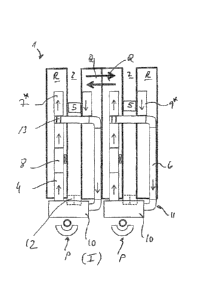
The Figures 1 and 2 illustrate a storage facility, which is designated as a
whole by the
reference numeral 1, having a plurality of storage racking aisles 2 and
storage racking
units R having a plurality of levels 3.
The storage racking units R are disposed in such a manner that the storage
racking
units R which are not disposed on the outside are each disposed in pairs
adjoining
one another and have a storage racking aisle 2 on one side. The storage
racking
units R located on the inside in each case abut one another "back-to-back".
Every other storage racking aisle 2 is provided with a lift 8 having at least
one or more
locations/ positions for units T in each case. The lift 8 is adjoined by an
inbound line 4
and a removal-from-storage feeding line or outbound conveyor 6 or can be
configured
vice versa. Corresponding inbound and outbound buffer conveyors 7* and 9*,
provided as an option, are disposed between the lift 8 and the storage racking
R in the
picking level I, in order to decouple the lift 8 from the single level AS/RS 5
(also
CA 02917953 2016-01-11
WO 2015/007514 PCT/EP2014/063930
11
referred to as shuttles) which travel in the storage racking aisle 2.
Lift 8 is of the drive through type, meaning that a storage unit T may either
use the lift
to change levels or pass through the lift 8, in a conveyor manner, so that it
may be
conveyed via conveyor 6 and RAT 13 to inbound-buffer 7 on the storage level or
from
the lift 8 conveyed via conveyor 6 to the picking station 10.
The lift 8 is arranged in one of the pair of racking units R and is fed by the
storage-
entry feeding line 4 and itself feeds the outbound line 6 in the picking level
I.
The shuttle 5 is fed by an inbound-buffer 7 and feeds into an outbound-buffer
9,
wherein both buffers 7, 9 are arranged within the racking unit R directly
behind the
conveyor loop 11.
The outbound-buffer 9 feeds into the conveyor loop 11 or outbound line 6 and
inbound-buffer 7 is fed by the conveyor loop or outbound line 6 after the lift
8.
For this reason the conveyor loop 11 or outbound line 6 contains a junction or
switch
13 to selectively feed the inbound-buffer 7.
Therefore, each aisle 2 in the picking level I is connected to a picking
station 10 by a
conveyor loop 11 formed with the storage-entry feeding line 4, the lift 8 and
the
outbound line 6, to which storage units T are fed for picking for fulfilling
orders by the
picker P.
Picking station 10 may include temporary shelves 12 as a temporary store for
pre-
picking often used articles.
The shuttles 5 are provided in each storage racking aisle 2 and in each level
Ill. These
are thus a so-called "captive" variant, in which the shuttles or satellite
vehicles 5 are
fixedly allocated to a level 3 and do not change levels or aisles, which
theoretically
would be possible.
The shuttles 5 include a transport platform for receiving/carrying the
respective
storage unit T (paperboard container, tray, totes, container, goods without
any loading
CA 02917953 2016-01-11
WO 2015/007514 PCT/EP2014/063930
12
aids, etc.). Disposed in each case to the side on the transport platform are
telescopic
arms which push the storage unit T off, or pull it onto, the platform. In
addition, the
telescopic arms are extendible on both sides of the storage racking aisle 2
into the
racking units R and have fingers which can be open and close in a known
manner.
Particular exchange locations Q for cross-conveyance of storage units T from
one
racking R into the adjacent racking R are provided in each level 3 of the
storage
racking units R, so that the storage units T are exchanged inside the storage
racking
units R themselves and it is possible to dispense with or at least minimize
correspond-
ing work in the pre-zone. The locations Q for cross-conveyance of storage
units T are
located directly behind the buffers 7, 9 in the racking units R. However they
may of
course also be located at different positions within the racks.
Therefore, the shuttle 5 or the telescopic arms thereof can deposit storage
units T in
the cross conveyance locations Q and push them to the corresponding location
in the
adjacent racking R. For this purpose, the respective storage unit T is being
acted
upon by the finger of the telescopic arms beyond a rear storage location of
one cross
conveyance location Q of the first racking R into the respective rear storage
location
of the adjacent cross conveyance location Q of the adjacent racking R.
A plurality of cross conveyance locations Q may be, so that they do not have
to be
emptied immediately so operation of neighboring shuttles on the same level can
be
decoupled. In addition, extra cross conveyance locations, depending upon the
compilation of the order to be retrieved can be used as a buffer store, from
which
articles are retrieved from the location directly.
For the purpose of retrieval in other non-picking levels III, the storage
units T are
taken from the storage racking R by the shuttle 5 and are discharged onto the
retrieval
or outbound buffer 9 which conveys the storage units T further to the lift 8
and thus to
the outbound feeding line 6, i.e. loop 11 in the picking level I. In the
reverse scenario,
placement into storage in the respective storage racking R is effected by the
inbound
lines 4, the lift 8 and the storage buffer 7 and the shuttle 5. If necessary
the normal
operation direction may be reversed, such that conveyor 6 is used for storage
and
conveyor 4 is used for feeding the picking station 10.
CA 02917953 2016-01-11
WO 2015/007514 PCT/EP2014/063930
13
In a usual picking process for order fulfillment, the picker P takes the goods
out of the
storage unit T conveyed from the loop 11 or line 6 out of the storage 1 to
picking
station 10 and puts them into provided order carrier like cartons or totes.
After processing the storage unit T is transported back into the storage
system 1 via
inbound line 4.
The Figures 3 and 4 illustrate a second storage facility 1, which is similar
to the one
described above and is therefore designated with like reference numerals and
only
substantial differences will be discussed below.
In contrast to storage facility 1 above, this storage facility has two picking
levels I and
II arranged on top of each other. Their structure is similar to picking level
I described
above.
However, a first lift 8a arranged in one of the pair of racking units R1 is
fed by the
storage-entry feeding line 4a and itself feeds the outbound line 6a of
conveyor loop
11 a in first picking level I, just as in facility 1 above, but
circumnavigates around a
second lift 8b arranged in the other of the pair of racking units R2, which is
also of the
drive-through-type and is fed by the storage-entry feeding line 4b and itself
feeds the
outbound line 6b of conveyor loop lib in a second picking level II, wherein
the
conveyor loop llb circumnavigates around the first lift 8a in the second
picking level
II.
In the non-picking levels III (see figure 4) the lifts 8A, 8B are fed by an
inbound-buffer
7 and feed into an outbound-buffer 9, as described above.
So, the system basically includes two pick stations 10 located one on top of
another in
levels I and II and two drive-thru lifts 8A, 8B per aisle 2, wherein each lift
8a, b serves
one level I, II of pick stations 10 only.
Directly connected to the conveyor loop 11 (or conveyor 6) are two buffer
conveyors
7*, 9*. One buffer conveyor 7* transports the units T for storage by shuttle
5, the other
one 9* is installed on the opposite side for buffering units T that come from
the
storage merged into the conveyor loop 11 to be transported to the picking
station 10.
CA 02917953 2016-01-11
WO 2015/007514 PCT/EP2014/063930
14
Also there are two optional RATs 13, which are only used/installed if levels I
and II are
served by shuttles 5 and the buffer conveyors 7*, 9* for diverting units
onto/from
outbound conveyor 6.
The special design of the conveyor loop 11 is that it is only connected to one
lift 8 and
one picking station 10.
For example, on the pick level I, the conveyor 6a is routed around either in
front or
behind of the second lift 8b without any connection to it and connected to
picking
station 10a. Likewise, on pick level II, the conveyor 6b circumnavigates the
first lift 8a
and connected to picking station 10b in the same but mirrored manner.
The shuttles 5 have different working ranges within this system. The shuttles
5 on the
two picking levels I, II only need to drive to the buffer conveyors 7*, 9* to
serve the
system with units T allocated to these levels.
The shuttles 5 in the other non-picking (or storage only) levels Ill have full
access to
the complete aisle 2 because there is no conveyor loop linking to the picking
stations
10. However there are two pair of buffer conveyors 7, 9 installed serving the
lifts in
one direction at each side of the aisle and the other direction on the other
side of the
aisle.
So the shuttle 5 passes the lifts 8 and can either drop units on the one side
to the
outbound buffer conveyor 9 to supply the lift with goods or on the other side
it can pick
up units T from the inbound buffer conveyor 7 coming from the lift.
With this design the both picking stations 10 have full accessibility to every
non-
picking level Ill, but the levels I, II connecting the picking stations 10
only have the
accessibility to either picking station 10a or 10b located at the same level
unless unit
T is routed through the pick station to get to another loop.
When a storage unit T stored in the racking R is needed for picking, the
shuttle 5 picks
it up and transports it to cross conveyance location Q, if the unit is not in
the desired
aisle 2, from where it is transferred to the adjoining aisle and picked up by
shuttle 5.If
CA 02917953 2016-01-11
WO 2015/007514 PCT/EP2014/063930
necessary this process is repeated, until the unit reaches the destination
aisle 2.
In the final aisle 2 the shuttle 5 picks up the unit T and transports it to
the outbound
buffer conveyor 9.
5
If the unit T is brought to the buffer conveyor 9 at the picking station level
I or II, it
waits on the buffer until the time for this unit has come (i.e. the conveyor
has a
window/free space for the unit according to the required retrieval sequence of
the
order to be fulfilled) and is then merged into the outbound conveyor 6 of the
loop 11 in
10 the right sequence.
If the unit T is brought to the buffer conveyor 9 at another non-pinking level
III, it will
be picked by the lift 8 then dropped to the outbound conveyor 6 on the picking
level I,
II and then conveyed within the conveyor loop 11 to the picking stations 10
where it is
15 processed.
After picking is performed at the picking station 10, the unit T is returned
back onto the
inbound conveyor 4 on which this unit is then returned into the storage
racking.
The unit can be elevated to a storage level III or simply pass through the
lift 8 if the
storage destination is the picking level I, II.
Once the unit is brought to the designated level III, it is dropped to the
buffer conveyor
7 connected with the lift 8 serving the desired storage level III. Afterwards
the shuttle 5
in the corresponding aisle 2 of the destination level picks up the storage
unit T and
stores it into the desired racking location.
The units T on the outbound conveyor 6 on the way to the picking station 10 do
not
interfere with the other lift because the conveyor 6 or loop 11 is routed
around this lift.
Many of the below embodiments have similar or like devices, installations etc.
which
are therefore indicated by same reference numerals.
However, in the picking levels I and II the shuttles 5 and the buffer
conveyors 7, 9 are
CA 02917953 2016-01-11
WO 2015/007514 PCT/EP2014/063930
16
optional as are also the cross conveyance locations Q.
Also there are two optional RATs 13, which are only used/installed if levels I
and II are
served by shuttles 5 and the buffer conveyors 7*, 9* for diverting units
onto/from
outbound conveyor 6.
Figure 5 is similar to the embodiment shown in figure 3. Non-picking levels
III are the
same as in figure 4, but second pair of buffer conveyors 7, 9 being optional
in a rack
R. When no second pair of buffer conveyors are used, the buffer conveyors are
alternated in their conveying direction in every or every few levels, i.e. in
even levels a
rack R has buffer conveyors in a certain direction and in odd level in
opposite direction
if additional pair of buffer conveyors on each level are not allocated. Such
an
arrangement realizes the dual cycle lift operation which improves lift
performance.
Picking-level I has an inbound conveyors 4 which leads into both lift 8A and
8B, which
are of the drive-through kind. The units T are intelligently distributed over
two inbound
conveyors 4 for optimum operation of lifts 8 and shuttles 5. Lift 8 in turn
obviously may
allow for a level change of units. To dispatch units from the racking to the
picking
station 10 etc. units are conveyed from lift 8A and 8B in level I onto
outbound
conveyor 6, where units T are intelligently merged from two lifts 8 for
optimum
operation of lifts 8, shuttles 5 and managing sequencing and for which the
units are
redirected via a RAT 13 onto outbound conveyor 6 and on to the picking station
10.
Alternatively they may pass through RAT 13 onto buffer conveyor 7* in level I.
Units to
be dispatched from racking in level I are dropped off onto buffer conveyor 9*
by
shuttle 5 in level I, which is connected to outbound conveyor 6.
Level I also has a second lift 8B in the same level together with conveyors 4,
6 so that
the power of two lifting carriages can be utilized with a single picking
station level.
There may be more than one pick station per aisle and each are then located on
top
of each other.
As indicated by the hashed lines in level I the buffer conveyors 7*, 9*,
shuttles 5 and
RAT's 13 as well as cross-conveyance locations Q are optional on this picking
level.
The embodiment of figure 6 has a pair of inbound and outbound conveyors 4, 6
per
CA 02917953 2016-01-11
WO 2015/007514
PCT/EP2014/063930
17
aisle alternating by conveyor levels, so that each level 1-A has two inbound
conveyors
4 and each level I-B has two outbound conveyors 6.
The two inbound conveyors 4 are directly on level 1-A and the two outbound
conveyors 6 are in a level I-B, which is not a full level below (or above),
but beneath
level 1-A such that they both feed / dispatch from one picking level (same
picking
station 10).
The picking station is connected to the lift via common connection conveyors
14
where units T are intelligently distributed over two inbound conveyors 4 for
optimum
operation of lifts 8 and shuttles 5 and the two outbound conveyors 6 are
connected
where units T are intelligently merged from two lifts for optimum operation of
lifts,
shuttles and managing sequencing and connected to the corresponding picking
station 10 by a common connection conveyor 15.
Non-picking levels III are the same as in figure 4, with the second pair of
buffer
conveyors 7, 9 being optional in a rack R.
In figure 7 the picking stations 10 are arranged on top (or below or even in
the middle
of) the storage racking R and on both sides of an aisle 2. More than one
picking level
can be used.
So each aisle 2 can be connected to two picking stations 10, one at each end
(1-1), or
alternatively each two aisles can be connected to two stations 10 at each end,
consolidated by conveyors 16 (1-2).
The picking level 1 is sourced by the lifts 8 and the stations 10 are
connected by
inbound conveyors 4 and outbound conveyors 6.
The non-picking levels III are the same as above but always have a second of
buffer
conveyors 7, 9 for embodiment of level 1-1 whilst those are still an option
for
embodiments of level 1-2. They may have cross conveyance locations Q to both
sides
of the lifts 8.
In figure 8 each aisle 2 of the picking level 1 has a pair of lifts 8, one in
each rack R,
CA 02917953 2016-01-11
WO 2015/007514 PCT/EP2014/063930
18
one for inbound 8A and another one for outbound 8B transportation with inbound
conveyor 4 feeding it and outbound conveyors 6 receiving from it respectively
supplied from/to picking stations 10. More than one picking level may be
installed. The
other levels III correspond to level III as described above.
With such an arrangement units stored in any level can be routed to any
picking level
and vice versa.
In Figure 9 three alternative layouts for connecting picking stations 10 to
lifts 8 are
shown. The non-picking levels III are the same as figure 5.
The picking levels IA, B are similar to figure 5 in that the outbound conveyor
6
circumvents one of the two lifts 8 of this level for sourcing of units to the
picking
station 10.
In embodiment of level IA the outbound conveyor is then split up and conveys
units to
the picking station 10A on two sides, as it is a dual person picking station.
Finished
order units may then be dispatched via shipping conveyor 20 directly from the
picking
station 10. Units that are to be returned to storage are dispatched
correspondingly on
two inbound conveyors 4, arranged flush to or below the outbound conveyor 6
that are
merged and then divided again when entering the storage racking.
In embodiment of level IB the picking station 10B the outbound conveyor 6 is
arranged directly beneath/below (indicated by hashed lines) the inbound
conveyors 4
and is split up to conveys units to the picking station 10B from below at two
locations,
typically one for order units 0 and one for donor units D but may act as dual
person
picking station that works similar way to level IA.
Dispatch of the units is allowed by two inbound conveyors 4 that are merged
and then
divided again when entering the storage racking.
In level IC the picking station 10C is also a two person operated picking
station which
is sourced by two outbound conveyors 6 directly connected to lifts and is
dispatched
by one inbound conveyor 4 between the racks of aisle 2connected to both lifts
8 via
conveyor 16 where unit T is intelligently diverted into two lifts. The station
10C may
CA 02917953 2016-01-11
WO 2015/007514
PCT/EP2014/063930
19
have a shipping conveyor 20 connection for immediate dispatch of finished
units.
In figure 10 each rack R of an aisle 2 has a lift 8 and there are two conveyor
levels as
in figure 6. However this embodiment has one inbound conveyor 4 and one
outbound
conveyor 6 on each level I-A, I-B but with altered directions and both levels
feed /
dispatch dedicated picking stations 10 belonging to each level.
In other words, the lifts 8 either stop at different levels (A or B) to serve
the
corresponding conveyors 4 or 6.
Non-picking levels III are the same as in figure 4, with the second pair of
buffer
conveyors 7, 9 being optional in a rack R and their direction alternating by
each level
or each few levels if such a second pair of buffer conveyors is not used.
The above embodiments may be combined with each other in many ways within the
scope of the invention.