Note: Descriptions are shown in the official language in which they were submitted.
CA 02918037 2016-01-11
WO 2015/009451
PCMJS2014/045218
1
LOW PROFILE PASSIVE PROTECTOR FOR AN I.V. CATHETER
CROSS-REFERENCE TO RELATED APPLICATIONS
Not Applicable
STATEMENT RE: FEDERALLY SPONSORED RESEARCH/DEVELOPMENT
Not Applicable
BACKGROUND
1. Technical Field
The present disclosure relates generally to a universal passive protector for
an
IV catheter, and more specifically to a universal passive protector having a
low-
profile flashback chamber relative to a finger-press plate to define a more
ergonomically friendly configuration, which in turn, simplifies withdrawal of
a
hypodermic needle after placement of the catheter within the patient's vein.
2. Related Art
It is well known in the medical profession that various medical treatments and
procedures oftentimes require the insertion or withdrawal of fluid from a
patient.
Intravenous needles are commonly employed to achieve such insertion or
withdrawal
of fluid. However, in some instances, the needle may be required to remain in
the
patient for an extended period of time, such as when introducing or
withdrawing large
amounts of fluid. Under these circumstances, metal needles are typically
unfavorable
due to their rigid structure and sharp distal tip which can cause trauma to
the patient's
vein. In view of the disadvantages associated with metal needles, medical
professionals commonly use a catheter for such applications.
A conventional catheter typically includes a generally flexible tube having a
hard/rigid distal tip. The catheter is typically inserted into a patient's
vein using a
catheter introduction device. Various catheter introduction devices have been
developed and include through-the-needle catheters, as well as over-the-needle
catheters. A through-the-needle catheter is inserted into an anatomical
passage of the
patient through the use of a cannula, which typically includes an elongate,
metal
needle which punctures the skin, tissue and vein wall to provide a path for
placement
of the catheter in the vein. When the needle pierces the vein, blood will
"flashback"
CA 02918037 2016-01-11
WO 2015/009451
PCT/1JS2014/045218
through the needle and into a flashback chamber typically located at the
proximal end
of the needle. Thus, the "flashback" is an indication to the medical
technician that the
needle has been properly inserted into the vein. At this point, the catheter
is
maintained stationary within the vein and the needle is withdrawn and removed
from
the catheter. The needle may have score lines formed therein to allow a
medical
technician to tear or pull the needle apart to remove the needle from the
catheter once
the catheter is removed from the patient.
Over-the-needle catheters are also commonly used by medical technicians, and
typically include a thin catheter having a hub attached to its proximal end.
The
catheter is advanced over a rigid cannula, such as a needle, with the cannula
and
catheter being simultaneously advanced into a desired anatomical passage of a
patient.
Once the catheter has been inserted into the anatomical passage of the
patient, the
cannula is typically removed from the catheter by retracting the cannula
through the
catheter. The action of retracting the cannula can undesirably expose the
medical
technician as well as the patient to accidental contact with the cannula,
particularly the
piercing tip of the needle. Such accidental needle sticks are a serious
concern in view
of such diseases as Acquired Immune Deficiency Syndrome ("AIDS"), which can be
transmitted through the exchange of bodily fluids with an infected person. In
particular, a needle that has been used to place a catheter in the vein of an
AIDS
infected person may be a vehicle for transmission of the disease to the
medical
technician.
A number of protective devices have been developed recently to help reduce
the incidence of disease and transmission through needle sticks. Many of the
protective devices employ a protective, elongate sheath into which the needle
is
retracted as the needle is withdrawn from the patient. Along these lines, when
the
needle is withdrawn, its sharp distal tip is safely enclosed within the
sheath, which is
typically formed from a rigid material.
Operation of the protective devices generally includes an actuation mechanism
connected to the needle, which is operated by the fingers of the medical
technician.
The technician uses various structures on the protective device to push
against or pull
on for retracting the needle within the sheath. However, in many protective
devices,
the flashback chamber is positioned in a manner which makes it difficult for
the
medical technician to easily grasp and manipulate the protective device in its
intended
CA 02918037 2016-01-11
WO 2015/009451
PCT/1JS2014/045218
3
manner. Such difficulty may lead to improper operation of the protective
device,
which may lengthen the process of inserting the catheter, or compromise the
protective nature of the device.
Accordingly, there is a need in the medical field for an improved protective
device that is sized and configured to facilitate withdrawal of the needle
within a
protective element. The present invention addresses this need, as will be
discussed in
more detail below.
BRIEF SUMMARY
According to an aspect of the invention, there is provided a universal passive
protector having a low-profile flashback chamber which forms a more
ergonomically
compatible configuration relative to prior art passive protectors. The
ergonomically
friendly configuration allows the medical technician's fingers to easily
interface with
a finger-press plate for properly operating the protector when withdrawing the
needle
therein after insertion of the catheter into the patient. Despite the reduced
profile of
the flashback chamber, the flashback chamber is configured to perform its
conventional function of providing a visual indication that the catheter has
been
properly inserted into the patient's vein. However, the low-profile of the
flashback
chamber minimizes interference with the fingers of the medical technician to
allow
the medical technician to easily operate the device.
According to one embodiment, there is provided a low-profile universal
passive protector for an IV catheter comprising a hypodermic needle and an
over-the-
needle catheter removeably disposed about the hypodermic needle. An elongate
sheath is detachably engaged with the over-the-needle catheter and defines a
sheath
cavity and a longitudinal axis. A slider is connected to the hypodermic needle
and is
movable along the sheath between a first position and a second position, such
that the
hypodermic needle is drawn into the sheath cavity as the slider moves from the
first
position toward the second position. A finger-press plate is coupled to the
sheath and
extends beyond the slider in a direction perpendicular to the longitudinal
axis to
define a plate height. A flashback body is coupled to the slider in a manner
such that
the flashback body and slider collectively define a cavity in fluid
communication with
the hypodermic needle. The flashback body is sized and configured to extend
from the
CA 02918037 2016-01-11
WO 2015/009451
PCT/1JS2014/045218
4
slider in a direction perpendicular to the longitudinal axis to define a
flashback body
height that is less than the plate height.
The slider may include a first end and an opposing second end, wherein the
first end faces the finger-press plate. The flashback body may be coupled to
the slider
such that no portion of the flashback body extends from the slider beyond the
second
end.
The flashback body height may be less than 1/3 of the plate height. The
flashback body may include a flashback plate and a flashback cylinder coupled
to the
flashback plate, wherein the flashback plate defines a plane that is
substantially
parallel to the longitudinal axis, and the flashback cylinder defines a
cylinder axis
substantially parallel to the longitudinal axis. The flashback cylinder may
define an
opening which extends into the flashback plate. The flashback cylinder may be
integrally fooned with the flashback plate. The flashback cylinder may include
a
curved end portion and an open end portion opposite the curved end portion,
wherein
the flashback cylinder is arranged such that the curved end portion faces the
finger-
press plate. The curved end portion may intersect with the flashback plate at
the
approximate midpoint of the slider in a longitudinal cross section generally
perpendicular to the flashback plate.
The protector may include a locking element coupled to the sheath and
extending into the sheath cavity. The slider may be configured to engage with
the
locking element when the slider is in the second position so as to lock the
slider in
place. The locking element may include a locking tab which engages with a
corresponding locking tab on the slider when the slider is in the second
position.
The presently contemplated embodiments will be best understood by reference
to the following detailed description when read in conjunction with the
accompanying
drawings.
BRIEF DESCRIPTION OF THE DRAWINGS
These and other features and advantages of the various embodiments disclosed
herein will be better understood with respect to the following description and
drawings, in which:
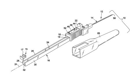
Figure 1 is an upper perspective view of a low-profile universal passive
protector constructed in accordance with an embodiment of the present
invention, the
CA 02918037 2016-01-11
WO 2015/009451
PCT/1JS2014/045218
universal passive protector having a cover coupled thereto and extending over
a
hypodeimic needle and an over-the-needle catheter;
Figure 2 is an upper perspective view of the universal passive protector and
cover, with the cover removed from the universal passive protector to expose
the
5 hypodeimic needle and the over-the-needle catheter;
Figure 3 is a top plan view of the universal passive protector;
Figure 4 is a side view of the universal passive protector;
Figure 5 is an enlarged, partial, side sectional view of the universal passive
protector illustrating a low-profile height relative to a finger-press plate;
Figure 5A is an enlarged side sectional view of the distal end of the catheter
positioned on the needle;
Figure 6 is an upper perspective view showing use of the universal passive
protector for inserting a catheter into a patient;
Figure 7 is a side view of the universal passive protector with the slider and
needle in a deployed configuration;
Figure 8 is a side view of the universal passive protector with the slider and
needle transitioned toward a retracted configuration;
Figure 9 is an upper perspective view of the catheter detached from the sheath
and inserted in a patient; and
Figure 10 is a top view of the catheter detached from the sheath and the
hypodermic needle retracted within the sheath.
Common reference numerals are used throughout the drawings and the
detailed description to indicate the same elements.
DETAILED DESCRIPTION
The detailed description set forth below in connection with the appended
drawings is intended as a description of the presently preferred embodiments
of the
invention, and is not intended to represent the only form in which the present
devices
may be developed or utilized. It is to be understood, however, that the same
or
equivalent functions may be accomplished by different embodiments that are
also
intended to be encompassed within the spirit and scope of the invention. It is
further
understood that the use of relational teims such as first, second, and the
like are used
CA 02918037 2016-01-11
WO 2015/009451
PCT/1JS2014/045218
6
solely to distinguish one from another entity without necessarily requiring or
implying
any actual such relationship or order between such entities.
Referring now to the drawings, wherein the showings are for purposes of
illustrating a preferred embodiment of the present invention only, and are not
for
purposes of limiting the same, there is depicted a low-profile, universal
passive
protector 10 for use in inserting an over-the-needle IV catheter 12 into a
patient. The
universal passive protector 10 includes a hypodermic needle 14 that is
configured to
be withdrawn into a sheath 16 in response to movement of a slider 18 along the
sheath
16 from a deployed position to a retracted position. The slider 18 is
specifically
configured and adapted to include a flashback chamber 20 (see Figure 5) which
defines a low-profile in relation to a finger-press plate 22 to allow a
healthcare
technician to easily grasp the slider 18 with the technician's thumb and
middle finger,
while pressing the against the finger-press plate 22 with the technician's
index finger
for moving the slider 18 along the sheath 16.
The sheath 16 is an elongate member which defines a longitudinal axis 24 and
includes a top surface 26, a pair of opposed side surfaces 28, 30, a bottom
surface 32,
and a sheath cavity 34 extending into the sheath 16 from the top surface 26
thereof
along the length of the sheath 16. The exemplary embodiment of the sheath 16
defines
a substantially quadrangular cross section, although those skilled in the art
will
appreciate that the sheath 16 may define a variety of alternative cross-
sectional shapes
without departing from the spirit and scope of the present invention.
The slider 18 is slidably connected to the sheath 16 and is moveable along the
length of the sheath 16 between a first, extended position and a second,
retracted
position. The slider 18 is rigidly connected to the needle 14 such that
movement of the
slider 18 from the extended position toward the retracted position causes the
needle
14 to retract into the sheath cavity 34, as will be described in more detail
below. The
slider 18 includes a slider locking tab 19 (see Figure 5) which engages with a
distal
needle lock 15 for locking the slider 18 in retracted position. When the
slider 18 is
locked in the retracted position, the engagement between the distal needle
lock 15 and
the slider 18 restricts/prevents movement of the slider 18 from the retracted
position
toward the extended position so as to maintain the needle 14 within the sheath
16 for
preventing inadvertent needle sticks.
CA 02918037 2016-01-11
WO 2015/009451
PCT/1JS2014/045218
7
The distal needle lock 15 (i.e., a locking element) is coupled to the sheath
16
and extends into the sheath cavity 34 such that the slider 18 engages with the
distal
needle lock 15 when the slider 18 is in the retracted position. The particular
embodiment of the distal needle lock 15 includes a locking tab 17, which is
configured to engage with a slider locking tab 19 formed on the slider 18 when
the
slider 18 is in the fully retracted position. In particular, the slider
locking tab 19
extends over the distal needle lock tab 17 and into a locking cavity 21 formed
behind
the locking tab 17 to capture the slider locking tab 19 therein. By capturing
the slider
locking tab 19, movement of the slider 18 along the sheath 34 is prevented.
A flashback body 36 is connected to the slider 18 such that the flashback body
36 and the slider 18 collectively define the flashback chamber 20, which is in
fluid
communication with the fluid passageway defined by the hypodermic needle 14.
The
flashback chamber 20 fills with blood when the needle 14 is inserted into a
patient's
vein so as to provide a visual indication to the medical technician that the
needle 14
and catheter 12 are properly positioned.
The finger-press plate 22 is coupled to the sheath 16 and extends upwardly
therefrom. The finger-press plate 22 is specifically sized and configured to
serve as a
push-off point for the medical technician's index finger when transitioning
the slider
from the extended position toward the retracted position, as discussed in more
detail
below.
One aspect of the present invention pertains to the height differential
between
the flashback body 36 and the finger-press plate 22. In particular, the
flashback body
36 is specifically sized and configured to define a low-profile relative to
the finger-
press plate 22 to allow the medical technician's index finger to easily
interface with
the finger-press plate 22. In this regard, the flashback body 36 does not
interfere with
the medical technician's index finger when the slider 18 is positioned
adjacent the
finger-press plate 22 (i.e., when the slider 16 is in the extended position).
The finger-press plate 22 extends from the sheath 16 in a direction
substantially perpendicular to the longitudinal axis 24 beyond an upper
surface 38 of
the sider 18 to define a plate height "P." The flashback body 36 extends above
the
upper surface 38 of the slider 18 in a direction substantially perpendicular
to the
longitudinal axis 24 to define a flashback body height "F." The flashback body
height
F is less than the plate height P, and is preferably substantially less than
the plate
CA 02918037 2016-01-11
WO 2015/009451
PCT/1JS2014/045218
8
height P. In one embodiment, the flashback body height F is less than 1/3 of
the plate
height P, and in other embodiments, the flashback body height F is
significantly less
than 1/3 of the plate height P. In this regard, the plate height P may be
increased in
various embodiments of the universal passive protector 10 to increase the
height
differential between the plate height P and the flashback body height F so as
to make
it easier for the medical technician to interface with the finger-press plate
22 during
use of the protector 10.
According to another aspect of the present invention, the flashback body 36 is
additionally configured so as not to extend beyond the slider 18 in a
direction parallel
to the longitudinal axis 24. Along these lines, the slider 18 includes a first
end 40 and
an opposing second end 42, wherein the first end faces the finger-press plate
22 and
the second end 42 faces away from the finger-press plate 22. The flashback
body 36 is
preferably confined between the planes defined by the opposing first and
second ends
40, 42.
In one embodiment, the flashback body 36 includes a flashback plate 44 and a
flashback cylinder 46 coupled to the flashback plate 44. In a preferred
embodiment,
the flashback cylinder 46 is integrally formed with the flashback plate 44,
although
those skilled in the art will recognize that non-integral configurations may
be
employed without departing from the spirit and scope of the present invention.
The
flashback plate 44 defines a plane that is substantially parallel to the
longitudinal axis
24, and the flashback cylinder 46 defines a cylinder axis substantially
parallel to the
longitudinal axis 24. According to one implementation, the flashback cylinder
46
defines an opening disposed about the cylinder axis and sized to at least
partially
extend into the flashback plate 44, as can be seen in Figures 1 and 2, wherein
the
lower end of the opening extends partially into the flashback plate 44.
The flashback cylinder 46 includes a curved end portion 48 and an open end
portion 50 opposite the curved end portion 48. The flashback cylinder 46 is
arranged
such that the curved end portion 48 faces the finger-press plate 22. The
curved end
portion 48 intersects with the flashback plate 44 at the approximate midpoint
of the
slider 18 (i.e., between the first and second ends 40, 42) in a longitudinal
cross section
generally perpendicular to the flashback plate 44. In one implementation, the
opening
defined by the flashback cylinder 46 is too small to engage with conventional
fluid
CA 02918037 2016-01-11
WO 2015/009451
PCT/1JS2014/045218
9
insertion or extraction devices. In this regard, the fluid insertion or
extraction devices
interface directly with the catheter 12 for such procedures.
A plug 52 is inserted within the flashback cylinder opening to prevent blood
from exiting the flashback cavity 34. The plug 52 is preferably configured to
allow
gases to pass therethrough, while restricting the passage of liquids
therethrough.
As noted above, movement of the slider 18 from the extended position toward
the retracted position causes the needle 14 to retract into the sheath 16.
Along these
lines, the sheath 16 includes an opening 54 (see Figure 5) in communication
with the
sheath cavity 34 and through which the needle 14 extends. The needle 14
includes a
proximal portion 56 coupled to the slider 18 and an opposing distal portion
defining a
sharp distal tip 58 which slightly protrudes from a distal end of the catheter
12.
The catheter 12 defines a proximal end portion 60, a distal end portion 62,
and
a catheter passageway extending between the proximal and distal end portions
60, 62.
The catheter 12 includes a hub 64 positioned adjacent the proximal end portion
60. A
catheter tube 55, formed of a soft, flexible material, is attached to the hub
64. The
catheter tube 55 is configured to be inserted into a patient's vein, thereby
providing a
path for intravenous injection or aspiration of the patient. Along these
lines, the hub
64 is configured to be engageable with injection/aspiration devices via a
threaded luer
lock.
Figure 5A shows an enlarged, partial side sectional view of an embodiment of
the distal end portion 62 of the catheter 12. The catheter 12 includes a
hardened distal
tip 61 having an exposed segment 63 and an insertion segment 67, wherein the
insertion segment 67 is disposed within the catheter tube 55. The insertion
segment 67
is sized and configured to abut against a shoulder 71 formed on the needle 14,
wherein the outer diameter of the needle 14 transitions to a reduced diameter
at the
distal end thereof. The abutment between the hardened distal tip 61 and the
shoulder
71 prevents the catheter 12 from gathering or bunching up as the catheter 12
is
inserted into the patient. In this regard, the catheter tube 55 is typically
not frictionally
engaged with the needle 14 and is formed from a soft-flexible material such
that if the
hardened distal tip 61 did not engage with the shoulder 71, the catheter tube
55 would
likely gather and bunch up over the needle 14 as the needle 14 is advanced
into the
patient.
CA 02918037 2016-01-11
WO 2015/009451
PCT/1JS2014/045218
Although Fig. 5A shows the hardened distal tip 61 and the catheter tube 55 as
being separate elements which are joined together, it is additionally
contemplated that
the hardened distal tip 61 and the catheter tube 55 may be co-molded together
so as to
form a unitary body.
5 A detachable
cover 65 may be placed over the needle 14 and catheter 12
before using the protector 10 to protect the medical technician from an
inadvertent
needle stick. Along these lines, the cover 65 is removed before the needle 14
and
catheter 12 are inserted into the patient.
The sheath 16 is connected to a pair of retractable arms 66 (i.e., jaws)
10 specifically
configured and adapted to engage with the hub 64 when the slider 18 is in
the extended position, and to release the hub 64 as the slider 18 transitions
to the
retracted position. The arms 66 are pivotally connected to the sheath 16 and
are
moveable between a closed position, wherein the arms 66 engage with the hub
64, and
an open position, wherein the aims 66 release the hub 64. According to one
embodiment, the arms 66 are biased toward the open position, such that when
the
needle 14 is retracted within the sheath 16, the aims 66 release the hub 64.
In one implementation of the present invention, and referring now specifically
to Figure 10, each arm 66 includes a primary arm body 68 having a proximal
segment
coupled to the sheath 16, and a distal segment 70 configured to capture the
hub 64 of
the catheter 12 when the arms 66 are in the closed position. The arms 66 are
connected to the sheath 16 such that the primary arm bodies 68 are arranged in
generally opposed relation to each other and define a hub receiving cavity 72
therebetween. Each atm 66 additionally includes a secondary arm body 74
coupled to
the primary arm body 68 and extending into the hub receiving cavity 72. The
secondary arm bodies 74 are configured to interlock with each other and cover
the
opening 54 of the sheath 16 through which the needle 14 is retracted when the
needle
14 is in the fully retracted position. According to one embodiment, one
secondary aim
body includes a slot while the other secondary arm body includes a pin or post
which
resides within the slot to interlock the secondary aim bodies 74 to each
other. The
secondary arm bodies 74 each include a central aperture formed therein to
accommodate passage of the needle therethrough. The central apertures are co-
axially
aligned with each other when the amis 66 are in the closed position, to
thereby allow
the needle 14 to extend through each aperture. When the needle 14 is captured
within
11
the sheath 16, and the arms 66 transition to the open position, the apertures
move into
a non-aligned configuration, which effectively prevents the needle 14 from
leaving the
sheath 16. A spring 76 is engaged with the arms 66 and biases the arms 66
toward their
open position.
The foregoing describes an exemplary embodiment of the arms 66. For a more
detailed discussion of the arms 66, please refer to U.S. Patent No. 6,981,965,
entitled
Universal Passive Protector for an IV Catheter.
With the basic structural features of the device 10 described above, the
following discussion will focus on operation of the device 10. To insert the
catheter 12
into the patient's vein using the protector 10, a medical technician grasps
the protector
10 and aligns the distal, piercing end of the needle 14 with the patient's
vein. The
medical technician then punctures the patient's skin with the needle 14 and
guides the
needle 14 into the vein (see Figure 6). When the needle 14 has penetrated the
vein, the
flashback chamber 20 fills with blood. The technician inserts the needle 14
into the vein
deep enough so that the distal end of the catheter 12 traverses a wall of the
vein.
When the catheter 12 has been safely inserted into the vein, the technician
grasps the opposed sides of the sider 18 between the technician's thumb and
middle
finger (see Figures 6 and 7), while the technician's index finger resides on
top of the
slider 18 and against the finger-press plate 22. The low-profile configuration
of the
flashback body 36 reduces interference with the technician's index finger when
the
slider 18 is in the extended position. In this regard, the technician has
greater control
over the device 10, which minimizes shaking of the needle 14 within the
patient, and
allows the user to more easily push/press against the finger-press plate 22
for moving
the slider 18.
The technician then pulls the slider 18 from the extended position toward the
retracted position, which in turn, causes the needle 14 to retract into the
sheath 16.
When the slider 18 reaches the retracted position, the slider locking tab 19
is captured
within the locking cavity 21 of the distal locking element 15 so as to lock
the slider 18
in place on the sheath 16. Furthermore, when the needle 14 is completely
retracted into
the sheath 16, the arms 66 are no longer restrained by the needle 14, and thus
spring
into the open position. The catheter 12 is thus released from the arms and is
Date Recue/Date Received 2020-11-20
CA 02918037 2016-01-11
WO 2015/009451
PCT/1JS2014/045218
12
ready to engage with an injection or aspiration device. The needle 14 is
safely stowed
within the sheath 16 and the secondary arm bodies 74 block the needle 14 to
prevent
the needle 14 from exiting the sheath 16. In this regard, the protector 10
employs a
redundant locking/needle capturing system including the engagement between the
slider 18 and distal need lock 15 (i.e., the distal lock), as well as the
blockage of the
needle 14 by the secondary arm bodies 74 (i.e., the proximal lock) so as to
ensure the
safety of the medical professional and to guard against an accidental needle
stick.
The particulars shown herein are by way of example and for purposes of
illustrative discussion of the embodiments of the present invention only and
are
presented in the cause of providing what is believed to be the most useful and
readily
understood description of the principles and conceptual aspects. In this
regard, no
attempt is made to show more details than is necessary for a fundamental
understanding of the disclosure, the description taken with the drawings
making
apparent to those skilled in the art how the several forms of the presently
disclosed
invention may be embodied in practice.