Note: Descriptions are shown in the official language in which they were submitted.
CA 02918851 2016-01-21
WO 2015/010966 PCT/EP2014/065173
1
Context-Based Entropy Coding of Sample Values of a Spectral Envelope
Description
The present application is concerned with context-based entropy coding of
sample values
of a spectral envelope and the usage thereof in audio coding/compression.
Many modern state of the art lossy audio coders such as described in [11 and
[2] are
based on an MDCT transform and use both irrelevancy reduction and redundancy
reduction to minimize the required bitrate for a given perceptual quality.
Irrelevancy
reduction typically exploits the perceptual limitations of the human hearing
system in order
to reduce the representation precision or remove frequency information that is
not
, perceptually relevant. Redundancy reduction is applied to exploit the
statistical structure
or correlation in order to achieve the most compact representation of the
remaining data,
typically by using statistical modeling in conjunction with entropy coding.
Among others, parametric coding concepts are used to efficiently code audio
content.
Using parametric coding, portions of the audio signal such as, for example,
portions of the
spectrogram thereof, are described using parameters rather than using actual
time
domain audio samples or the like. For example, portions of the spectrogram of
an audio
signal may be synthesized at the decoder side with the data stream merely
comprising
parameters such as the spectral envelope and optional further parameters
controlling
synthesizing, in order to adapt the synthesized spectrogram portion to the
spectral
envelope transmitted. A new technique of such kind is Spectral Band
Replication (SBR)
according to which a core codec is used to code and transmit the low frequency
component of an audio signal, whereas a transmitted spectral envelope is used
at the
decoding side so as to spectrally shape/form spectral replications of a
reconstruction of
the low frequency band component of the audio signal so as to synthesize the
high
frequency band component of the audio signal at the decoding side.
A spectral envelope within the framework of coding techniques outlined above,
is
transmitted within a data stream at some suitable spectrotemporal resolution.
In a way
similar to the transmission of spectral envelope sample values, scale factors
for scaling
spectral line coefficients or frequency domain coefficients such as MDCT
coefficients, are
likewise transmitted in some suitable spectrotemporal resolution which is
coarser than the
original spectral line resolution, coarser for example in a spectral sense.
2
A fixed Huffman coding table could be used in order to convey information on
the samples
describing a spectral envelope or scale factors or frequency domain
coefficients. An
improved approach is to use context coding such as, for example, described in
[2] and [3],
where the context used to select the probability distribution for encoding a
value extends
both across time and frequency. An individual spectral line such as an MDCT
coefficient
value, is the real projection of a complex spectral line and it may appear
somewhat random
in nature even when the magnitude of the complex spectral line is constant
across time, but
the phase varies from one frame to the next. This requires a quite complex
scheme of
context selection, quantization, and mapping for good results as described in
[3].
In image coding, the contexts used are typically two-dimensional across the x
and y axis of
an image such as, for example, in [4]. In image coding, the values are in the
linear domain
or the power-law domain, such as for example by use of gamma adjustment.
Additionally,
a single fixed linear prediction may be used in each context as a plane
fitting and
rudimentary edge detection mechanism, and the prediction error may be coded.
Parametric
Golomb or Golomb-Rice coding may be used for coding the prediction errors. Run
length
coding is additionally used to compensate for the difficulties of directly
encoding very low
entropy signals, below 1 bit per sample, for example, using a bit based coder.
However, despite the improvements in connection with the coding of scale
factors and/or
spectral envelopes, there is still need for an improved concept for coding
sample values of
a spectral envelope. Accordingly, it is an object of the present invention to
provide a concept
for coding spectral values of a spectral envelope.
Embodiments described herein are based on the finding that an improved concept
for
coding sample values of a spectral envelope may be obtained by combining
spectrotemporal prediction on the one hand and context-based entropy coding
the
residuals, on the other hand, while particularly determining the context for a
current sample
value dependent on a measure for a deviation between a pair of already
coded/decoded
sample values of the spectral envelope in a spectrotemporal neighborhood of
the current
sample value. The combination of the spectrotemporal
CA 2918851 2017-07-20
CA 02918851 2016-01-21
3
WO 2015/010966 PCT/EP2014/065173
prediction on the one hand and the context-based entropy coding of the
prediction
residuals with selecting the context depending on the deviation measure on the
other
hand harmonizes with the nature of spectral envelopes: the smoothness of the
spectral
envelope results in compact prediction residual distributions so that the
spectrotemporal
intercorrelation is almost completely removed after the prediction and may be
disregarded
in the context selection with respect to the entropy coding of the prediction
result. This, in
turn, lowers the overhead for managing the contexts. The use of the deviation
measure
between already coded/decoded sample values in the spectrotemporal
neighborhood of
the current sample value, however, still enables the provision of a context-
adaptivity which
improves the entropy coding efficiency in a manner which justifies the
additional overhead
caused thereby.
In accordance with embodiments described hereinafter, linear prediction is
combined with
the use of the difference value as the deviation measure, thereby keeping the
overhead
for the coding low.
In accordance with an embodiment, the position of the already coded/decoded
sample
values used to determine the difference value finally used to select/determine
the context
is selected such that they neighbor each other, spectrally or temporally, in a
manner co-
aligned with the current sample value, i.e. they lie along one line in
parallel to temporal or
spectral axis, and the sign of the difference value is additionally taken into
account when
determining/selecting the context. By this measure, a kind of "trend" in the
prediction
residual can be taken into account when determining/selecting the context for
the current
sample value while merely reasonably increasing the context managing overhead.
Preferred embodiments of the present application are described below with
regard to the
figures, among which:
Fig. 1 shows a schematic of a spectral envelope and illustrates its
composition
out of sample values and a possible decoding order defined thereamong as
well as a possible spectrotemporal neighborhood for a currently
coded/decoded sample value of the spectral envelope;
Fig. 2 shows a block diagram of a context-based entropy encoder for
encoding
sample values of a spectral envelope in accordance with an embodiment;
CA 02918851 2016-01-21
4
WO 2015/010966 PCT/EP2014/065173
Fig. 3 shows a schematic diagram illustrating a quantization function
which may
be used in quantizing the derivation measure;
Fig. 4 shows a block diagram of a context-based entropy decoder
fitting to the
encoder of Fig. 2;
Fig. 5 shows a block diagram of a context-based entropy encoder for
encoding
sample values of a spectral envelope in accordance with a further
embodiment;
Fig. 6 shows a schematic diagram illustrating placement of the
interval of entropy
coded possible values of the prediction residual relative to the overall
interval of possible values of the prediction residuals in accordance with an
embodiment using escape coding;
Fig. 7 shows a block diagram of a context-based entropy decoder
fitting to the
encoder of Fig. 5;
Fig. 8 shows a possible definition of a spectrotemporal neighborhood
using a
certain notation;
Fig. 9 shows a block diagram of a parametric audio decoder in
accordance with
an embodiment;
Fig. 10 shows a schematic illustrating a possible implementation variant of
the
parametric decoder of Fig. 9 by showing the relationship between the
frequency interval covered by the spectral envelope on the one hand and
the fine structure covering another interval of the overall audio signal's
frequency range on the other hand;
Fig. 11 shows a block diagram of an audio encoder fitting to the
parametric audio
decoder of Fig. 9 according to the variant of Fig. 10;
Fig. 12 shows a schematic diagram illustrating a variant of the
parametric audio
decoder of Fig. 9 when supporting IGF (Intelligent Gap Filling);
CA 02918851 2016-01-21
WO 2015/010966 PCT/EP2014/065173
Fig. 13 shows a schematic diagram illustrating a spectrum out of a fine
structure
spectrogram, i.e. a spectral slice, the IGF filling of the spectrum and the
shaping thereof in accordance with the spectral envelope in accordance
with an embodiment; and
5
Fig. 14 shows a block diagram of an audio encoder supporting IGF,
fitting to the
variant of the parametric decoder of Fig. 9 in accordance with Fig. 12.
As a kind of motivation of the embodiments outlined herein below, which are
generally
applicable to the coding of a spectral envelope, some thoughts which lead to
the
advantageous embodiments outlined below are presented now using Intelligent
Gap
Filling (IGF) as an example. IGF is a new method to significantly improve the
quality of an
encoded signal even at very low bitrates. Reference is made to the description
below for
details. In any case, IGF addresses the fact that a significant part of a
spectrum in the
high frequency region is quantized to zero due to typically insufficient bit
budget. In order
to preserve as well as possible the fine structure of the upper frequency
region, in IGF
information in the low frequency region is used as a source to adaptively
replace the
destination regions in the high frequency region which were mostly quantized
to zero. An
important requirement in order to achieve a good perceptual quality is
matching of the
decoded energy envelope of the spectral coefficients with that of the original
signal. To
achieve this, average spectral energies are calculated on spectral
coefficients from one or
more consecutive AAC scale factor bands. Computing average energies using
boundaries
defined by scale factor bands is motivated by the already existing careful
tuning of those
boundaries to fractions of the critical bands, which are characteristic to
human hearing.
The average energies are converted into a dB scale representation using a
formula similar
to the one for the AAC scale factors, and then uniformly quantized. In IGF,
different
quantization accuracy may be optionally used depending on the requested total
bitrate.
The average energies constitute a significant part of the information
generated by IGF, so
its efficient representation is of high importance for the overall performance
of IGF.
Accordingly, in IGF, scale factor energies describe the spectral envelope. The
Scale
Factor Energies (SFE) represent spectral values describing the spectral
envelope. It is
possible to exploit special properties of the SFE when decoding same. In
particular, it has
been realized that in contrast to [2] and [3], SFEs represent average values
of MDCT
spectral lines and accordingly their values are much more "smooth" and
linearly correlated
to the average magnitude of the corresponding complex spectral lines.
Exploiting this
CA 02918851 2016-01-21
6
WO 2015/010966 PCT/EP2014/065173
circumstance, the following embodiments use a combination of spectral envelope
sample
value prediction on the one hand and context-based entropy coding of the
prediction
residual using contexts depending on a measure of a deviation of a pair of
neighboring
already coded/decoded sample values of the spectral envelope on the other
hand. The
usage of this combination is particularly adapted to this sort of data to be
coded, i.e. the
spectral envelope.
In order to ease the understanding of the embodiments outlined further below,
Fig. 1
shows a spectral envelope 10 and its composition out of sample values 12 which
sample
the audio signal's spectral envelope 10 at a certain spectrotemporal
resolution. In Fig. 1,
the sample values 12 are exemplarily arranged along time axis 14 and spectral
axis 16.
Each sample value 12 describes or defines the height of the spectral envelope
10 within a
corresponding spatiotemporal tile covering, for example, a certain rectangle
of the
spatiotemporal domain of a spectrogram of an audio signal. The sample values
are, thus,
integrative values having been obtained by integrating a spectrogram over its
associated
spectrotemporal tile. The sample values 12 may measure the height or strength
of the
spectral envelope 10 in terms of energy or some other physical measure, and
may be
defined in the non-logarithmic or linear domain, or in the logarithmic domain,
wherein the
logarithmic domain may provide additional advantages due to its characteristic
of
additionally smoothening the sample values along axes 14 and 16, respectively.
It should be noted that as far as the following description is concerned, it
is assumed for
illustration purposes only that the sample values 12 are regularly arranged
spectrally and
temporally, i.e. that the corresponding spatiotemporal tiles corresponding to
the sample
values 12 regularly cover a frequency band 18 out of a spectrogram of an audio
signal,
but such regularity is not mandatory. Rather, an irregular sampling of the
spectral
envelope 10 by the sample values 12 may also be used, each sample value 12
representing the mean average of the height of the spectral envelope 10 within
its
corresponding spatiotemporal tile. The neighborhood definitions outlined
further below
may nevertheless be transferred to such alternative embodiments of an
irregular sampling
of the spectral envelope 10. A brief statement on such a possibility is
presented below.
Before, however, it is noted that the above mentioned spectral envelope may be
subject to
encoding and decoding for transmission from encoder to decoder for various
reasons. For
example, the spectral envelope may be used for the sake of scalability
purposes so as to
extend a core encoding of a low frequency band of an audio signal, namely
extending the
CA 02918851 2016-01-21
7
wo 2015/010966 PCT/EP2014/065173
low frequency band towards higher frequencies, namely into a high frequency
band which
the spectral envelope relates to. In that case, the context-based entropy
decoders/encoders described below could be part of an SBR decoder/encoder, for
example. Alternatively, same could be part of audio encoders/decoders using
IGF as
already mentioned above. In IGF, a high frequency portion of an audio signal
spectrogram
is additionally described using the spectral values describing the high
frequency portions
spectral envelope of the spectrogram so as to be able to fill zero-quantized
areas of the
spectrogram within the high frequency portion using the spectral envelope.
Details in this
regard are described further below.
Fig. 2 shows the context-based entropy encoder for encoding sample values 12
of a
spectral envelope 10 of an audio signal in accordance with an embodiment of
the present
application.
The context-based entropy encoder of Fig. 2 is generally indicated using
reference sign
and comprises a predictor 22, a context determiner 24, an entropy encoder 26
and a
residual determiner 28. The context determiner 24 and the predictor 22 have
inputs at
which same have access to the sample values 12 of the spectral envelope (Fig.
1). The
entropy encoder 26 has a control input connected to an output of context
determiner 24,
20 and a data input connected to an output of residual determiner 28. The
residual
determiner 28 has two inputs, one of which is connected to an output of
predictor 22, and
the other one of which provides the residual determiner 28 with access to the
sample
values 12 of the spectral envelope 10. In particular, residual determiner 28
receives the
sample value x currently to be coded at its input, while context determiner 24
and
predictor 22 receive at their inputs sample values 12 already having been
coded and
residing within a spectrotemporal neighborhood of the current sample value x.
The predictor 22 is configured to spectrotemporally predict the current sample
value x of
the spectral envelope 10 to obtain an estimated value 2. As will be
illustrated in
connection with a more detailed embodiment outlined below, predictor 22 may
use linear
prediction. In particular, in performing the spectrotemporal prediction,
predictor 22
inspects already coded sample values in a spectrotemporal neighborhood of
current
sample value x. See, for example, Fig. 1. The current sample value x is
illustrated using a
bold continuously drawn outline. Using hashing, sample values in the
spectrotemporal
neighborhood of current sample x are shown which, in accordance with an
embodiment,
form a basis for the spectrotemporal prediction of predictor 22. "a", for
example, denotes
CA 02918851 2016-01-21
8
WO 2015/010966 PCT/EP2014/065173
the sample value 12 immediately neighboring current sample x, which is co-
located to
current sample x spectrally, but precedes current sample x temporally.
Likewise,
neighboring sample value "b" denotes the sample value immediately neighboring
current
sample x, which is co-located to current sample value x temporally, but
relates to lower
frequencies when compared to current sample value x, and sample value "c" in
the
spectrotemporal neighborhood of current sample value x is the nearest neighbor
sample
value of current sample value x, which precedes the latter temporally, and
relates to lower
frequencies. The spectrotemporal neighborhood may even encompass sample values
representing next but one neighbors of current sample x. For example, sample
value "d" is
separated from current sample value x by sample value "a", i.e. it is co-
located to current
sample value x temporally and precedes current value x with merely sample
value "a"
being positioned therebetween. Likewise, sample value "e" neighbors sample
value x
while being co-located to current sample value x temporally, and neighboring
sample
value x along the spectral axis 16 with merely neighbor sample "b" being
positioned
therebetween.
As already outlined above, although the sample values 12 are assumed to be
regularly
arranged along time and spectral axes 14 and 16, this regularity is not
mandatory, and the
neighborhood definition and identification of neighboring sample values may be
extended
to such an irregular case. For example, neighbor sample value "a" may be
defined as the
one neighboring the upper left corner of the current sample's spectrotemporal
tile along
the temporal axis with preceding the upper left corner temporally. Similar
definitions may
be used to define other neighbors as well, such as neighbors b to e.
As will be outlined in more detail below, predictor 22 may, depending on the
spectrotemporal position of current sample value x, use a different subset of
all sample
values within the spectrotemporal neighborhood, i.e. a subset of {a, b, c, d,
e}. Which
subset is actually used may, for example, depend on the availability of the
neighboring
sample values within the spectrotemporal neighborhood defined by set {a, b, c,
d, e}. The
neighboring sample values a, d, and c may, for example be unavailable due to
current
sample value x immediately succeeding a random access point, i.e. a point in
time
enabling decoders to start decoding so that dependencies on previous portions
of the
spectral envelope 10 are forbidden/prohibited. Alternatively, neighboring
sample valuesb,
c, and e may be unavailable due to the current sample value x representing the
low
frequency edge of interval 18 so that the respective neighboring sample
value's position
falls outside interval 18. In any case, predictor 22 may spectrotemporally
predict the
CA 02918851 2016-01-21
9
wo 2015/010966 PCT/EP2014/065173
current sample value x by linearly combining already coded sample values
within the
spectrotemporal neighborhood.
The task of the context determiner 24 is to select one of the several
supported contexts
for entropy encoding the prediction residual, i.e. r = x - 2. To this end, the
context
determiner 24 determines the context for current sample value x dependent on a
measure
for a deviation between a pair of already coded sample values among a to e in
the
spectrotemporal neighborhood. In the specific embodiments outlined further
below, the
difference of a pair of sample values within the spectrotemporal neighborhood
is used as
a measure for a deviation therebetween, such as for example a ¨ c, b ¨ c, b ¨
e, a ¨ d or
the like, but alternatively other deviation measures may be used such as, for
example, a
quotient (i.e. a/c, b/c, aid), the difference to the power of a value unequal
to one, such as
an uneven number n unequal to one (i.e. (a-c)0, (b-c)", (a-d)8), or some other
type of
deviation measure such as, for example, a"-c", bn-c, a"-d" or (a/c)", (b/c)",
(aid)0 with n#1
Here, n could also be any value greater than 1, for example.
As will be shown in more detail below, the context determiner 24 may be
configured to
determine the context for the current sample value x dependent on a first
measure for a
deviation between a first pair of already coded sample values in the
spectrotemporal
neighborhood and a second measure for a deviation between a second pair of
already
coded sample values within the spectrotemporal neighborhood, with the first
pair
neighboring each other spectrally, and the second pair neighboring each other
temporally.
For example, difference values b ¨ c and a ¨ c may be used where a and c
neighbor each
other spectrally, and b and c neighbor each other temporally. The same set of
neighboring
sample values, namely {a, c, b}, may be used by predictor 22 to obtain the
estimated
value 2, namely, for example, by a linear combination of the same. A different
set of
neighboring sample values may be used for context determination and/or
prediction in
cases of some unavailability of any of sample values a, c and/or b. The
factors of the
linear combination may, as set out further below, be set so that the factors
are the same
for different contexts, in case of the bitrate at which the audio signal is
coded being
greater than a predetermined threshold, and the factors are set individually
for the
different contexts, in case of the bitrate being lower than a predetermined
threshold.
As an intermediate note, it should be mentioned that the definition of the
spectrotemporal
neighborhood may be adapted to the coding/decoding order along which context-
based
entropy encoder 20 sequentially encodes the sample values 12. As shown in Fig.
1, for
CA 02918851 2016-01-21
wo 2015/010966 PCT/EP2014/065173
example, the context-based entropy encoder may be configured to sequentially
encode
the sample values 12 using a decoding order 30 which traverses the sample
values 12
time instant by time instant with, in each time instant, leading from lowest
to highest
frequency. In the following, the "time instants" are denoted as "frames", but
the time
5 instants could alternatively be called time slots, time units or the
like. In any case, in using
such spectral traversal before temporal feed forward, the definition of the
spectrotemporal
neighborhood to extend into preceding time and towards lower frequencies
provides for
the highest feasible probability that the corresponding sample values have
already been
coded/decoded and are available. In the present case, the values within the
neighborhood
10 are always already coded/decoded, provided they are present, but this
may be different
for other neighborhood and decoding order pairs. Naturally, the decoder uses
the same
decoding order 30.
The sample values 12 may, as already denoted above, represent the spectral
envelope
10 in a logarithmic domain. In particular, the spectral values 12 may have
already been
quantized to integer values using a logarithmic quantization function.
Accordingly, due to
quantization, the deviation measures determined by context determiner 24 may
already
be integer numbers inherently. This is for example the case when using the
difference as
the deviation measure. Irrespective of the inherent integer number nature of
the deviation
measure determined by context determiner 24, context determiner 24 may subject
the
deviation measure to quantization and determine the context using the
quantized
measure. In particular, as will be outlined below, the quantization function
used by context
determiner 24 may be constant for values of the deviation measure outside a
predetermined interval, the predetermined interval including zero, for
example.
Fig. 3 exemplarily shows such quantization function 32 mapping unquantized
deviation
measures to quantized deviation measures where, in this example, the just
mentioned
predetermined interval 34 extends from -2.5 to 2.5, wherein unquantized
deviation
measure values above that interval are constantly mapped to quantized
deviation
measure value 3, and unquantized deviation measure values below that interval
34 are
constantly mapped to quantized deviation measure value -3. Accordingly, merely
seven
contexts are distinguished and have to be supported by the context-based
entropy
encoder. In implementation examples outlined below, the length of interval 34
is 5 as just-
exemplified, with the cardinality of the set of possible values of the
spectral envelope's
sample values being 2n (e.g. = 128), i.e. greater than 16 times the interval
length. In case
of escape coding being used as illustrated later, the range of possible values
of the
CA 02918851 2016-01-21
11
WO 2015/010966 PCT/EP2014/065173
spectral envelope's sample values may by defined to be [0; 21 with n being an
integer
selected such that 21 is below the cardinality of codable possible values of
the prediction
residual values which is, in accordance with a specific implementation example
described
below, 311.
The entropy encoder 26 uses the context determined by context determiner 24 to
efficiently entropy encode the prediction residual r which, in turn, is
determined by residual
determiner 28 on the basis of the actual current sample value x and the
estimated value
such as, for example, by means of subtraction. Preferably, arithmetic coding
is used. The
contexts may have associated therewith constant probability distributions. For
each
context, the probability distribution associated therewith assigns a certain
probability value
to each possible symbol out of a symbol alphabet of entropy encoder 26. For
example, the
symbol alphabet of entropy encoder 26 coincides with, or covers, the range of
possible
values of prediction residual r. In alternative embodiments, which are
outlined in more
detail below, a certain escape coding mechanism may be used so as to guarantee
that
the value r to be entropy encoded by entropy encoder 26 is within the symbol
alphabet of
entropy encoder 26. When using arithmetic coding, the entropy encoder 26 uses
the
probability distribution of the determined context determined by context
determiner 24, so
as to subdivide a current probability interval which represents the internal
state of entropy
encoder 26 into one subinterval per alphabet value, with selecting one of the
subintervals
depending on the actual value of r, and outputting an arithmetically coded
bitstream
informing the decoding side on updates of probability interval offset and
width by use of,
for example, a renormalization process. Alternatively, however, entropy
encoder 26 may
use, for each context, an individual variable length coding table translating
the probability
distribution of the respective context into a corresponding mapping of
possible values of r
onto codes of a length corresponding to the respective frequency of the
respective
possible value r. Other entropy codecs may be used as well.
For the sake of completeness, Fig. 2 shows that a quantizer 36 may be
connected in front
of the input of residual determiner 28, at which the current sample value x is
inbound so
as to obtain the current sample value x such as, as already outlined above, by
use of a
logarithmic quantization function, for example, applied to an unquantized
sample value x.
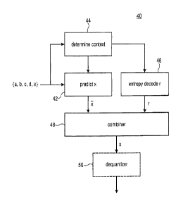
Fig. 4 shows a context-based entropy decoder in accordance with an embodiment,
which
fits to the context-based entropy encoder of Fig. 2.
CA 02918851 2016-01-21
12
WO 2015/010966 PCT/EP2014/065173
The context-based entropy decoder of Fig. 4 is indicated using reference sign
40 and is
construed similarly to the encoder of Fig. 2. Accordingly, context-based
entropy decoder
40 comprises a predictor 42, a context-determiner 44, an entropy decoder 46,
and a
combiner 48. Context determiner 44 and predictor 42 operate like predictor 22
and context
determiner 24 of encoder 20 of Fig. 2. That is, predictor 42 spectrotemporally
predicts the
current sample value x, i.e. the one currently to be decoded, to obtain the
estimated value
2 and outputs same to combiner 48, and context determiner 44 determines the
context for
entropy decoding the prediction residual r of current sample value x depending
on the
deviation measure between a pair of already decoded sample values within the
spectrotemporal neighborhood of sample value x, informing the entropy decoder
46 of the
context determined via a control input of the latter. Accordingly, both
context determiner
44 and predictor 42 have access to the sample values in the spectrotemporal
neighborhood. Combiner 48 has two inputs connected to outputs of predictor 42
and
entropy decoder 46, respectively, and an output for outputting the current
sample value. In
particular, entropy coder 46 entropy decodes the residual value r for current
sample
values x using the context determined by context determiner 44, and combiner
48
combines the estimated value 2 and the corresponding residual value r to
obtain the
current sample value x, such as for example by addition. For the sake of
completeness
only, Fig. 4 shows that a dequantizer 50 may succeed the output of combiner 48
so as to
dequantize the sample value output by combiner 48, such as for example by
subjecting
the same to a conversion from logarithmic domain to linear domain using, for
example, an
exponential function.
The entropy decoder 46 reverses the entropy encoding performed by entropy
encoder 26.
That is, entropy decoder also manages a number of contexts and uses, for a
current
sample value x, a context selected by context determiner 44, with each context
having a
corresponding probability distribution associated therewith which assigns to
each possible
value of r a certain probability which is the same as the one chosen by
context determiner
24 for entropy encoder 26.
When using arithmetic coding, entropy decoder 46 reverses, for example, the
interval
subdivision sequence of entropy encoder 26. The internal state of entropy
decoder 46 is,
for example, defined by the probability interval width of the current interval
and an offset
value pointing, within the current probability interval, to the subinterval
out of the same to
which the actual value of r of the current sample value x corresponds. The
entropy
decoder 46 updates the probability interval and offset value using the inbound
CA 02918851 2016-01-21
13
WO 2015/010966 PCT/EP2014/065173
arithmetically encoded bitstream output by entropy encoder 26 such as by way
of a
renormalization process and obtains the actual value of r by inspecting the
offset value
and identifying the subinterval which same falls into.
As already mentioned above, it may be advantageous to restrict the entropy
coding of the
residual values onto some small subinterval of possible values of prediction
residuals r.
Fig. 5 shows a modification of the context-based entropy encoder of Fig. 2 to
realize this.
In addition to the elements shown in Fig. 2, the context-entropy encoder of
Fig. 5
comprises a control connected between residual determiner 28 and entropy
encoder 26,
namely control 60, as well as an escape coding handler 62 controlled via
control 60.
The functionality of control 60 is illustrated in Fig. 5 in a cursory manner.
As illustrated in
Fig. 5, control 60 inspects the initially determined residual value r
determined by residual
determiner 28 on the basis of a comparison of the actual sample value x and
its estimated
value 2. In particular, control 60 inspects whether r is within or outside a
predetermined
value interval as illustrated in Fig. 5 at 64. See, for example, Fig. 6. Fig.
6 shows along the
x axis possible values of the initial prediction residual r, while the y axis
shows the actually
entropy encoded r. Further, Fig. 6 shows the range of possible values of the
initial
prediction residual r, namely 66, and the just mentioned predetermined
interval 68
involved in the check 64. Imagine, for example, that the sample values 12 are
integer
values between 0 and 21-1, both inclusively. Then, the range 66 of possible
values for the
prediction residual r may extend from -(2n-1) to 2n-1, both inclusively, and
the absolute
values of the interval bounds 70 and 72 of interval 68 may be smaller than or
equal to 2n-2,
that is the interval bounds' absolute values may be smaller than 1/8 of the
cardinality of
the set of possible values within range 66. In one of the implementation
examples set out
below in connection with xHE-AAC, the interval 68 is from -12 to +12
inclusive, the interval
bounds 70 and 72 are -13 and +13, and escape coding extends the interval 68 by
coding
a VLC coded absolute value namely extending interval 68 to -/+(13 + 15) using
4 bits and
to -/+(13 + 15 + 127) using another 7 bits, if previous 4 bits were 15. So the
prediction
residual can be coded in a range from -/+155, inclusive, in order to
sufficiently cover the
range 66 of possible values for the prediction residual which, in turn,
extends from -127 to
127. As can be seen, the cardinality of [127; 127] is 255, and 13, i.e. the
absolute values
of the internal bounds 70 and 72, is smaller than 32=255/8. When comparing the
length of
interval 68 with the cardinality of possible values codable using escape
coding, i.e. 1-
155;155], then one discovers that absolute values of the internal bounds 70
and 72 may
CA 02918851 2016-01-21
14
wo 2015/010966 PCT/EP2014/065173
advantageously be chosen to be smaller than 1/8 or even 1/16 of said
cardinality (here
311).
In case of the initial prediction residual r residing within interval 68,
control 60 causes
entropy encoder 26 to entropy encode this initial prediction residual r
directly. No special
measure is to be taken. However, if r as provided by residual determiner 28 is
outside
interval 68, an escape coding procedure is initiated by control 60. In
particular, the
immediate neighbor values immediately neighboring the interval bounds 70 and
72 of
interval 68 may, in accordance with one embodiment, belong to the symbol
alphabet of
entropy encoder 26 and serve as escape codes themselves. That is, the symbol
alphabet
of the entropy encoder 26 would encompass all values of interval 68 plus the
immediately
neighboring values below and above that interval 68 as indicated with curly
bracket 74
and control 60 would simply reduce the value to be entropy encoded down to the
highest
alphabet value 76 immediately neighboring the upper bound 72 of interval 68 in
the case
of residual value r being greater than upper bound 72 of interval 68, and
would forward
the lowest alphabet value 78 to entropy encoder 26, immediately neighboring
lower bound
70 of interval 68, in the case of the initial prediction residual r being
smaller than the lower
bound 70 of interval 68.
By use of the embodiment just outlined, the entropy encoded value r
corresponds to, i.e.
equals, the actual prediction residual in case of same being within interval
68. If, however,
the entropy encoded value r equals value 76, then it is clear that the actual
prediction
residual r of current sample value x equals 76 or some value above the latter,
and if the
entropy encoded residual value r equals value 78, then the actual prediction
residual r
equals this value 78 or some value below the same. That is, there are actually
two escape
codes 76 and 78 in that case. In case of the initial value r lying outside
interval 68, control
60 triggers escape coding handler 62 to insert within the data stream, into
which the
entropy encoder 26 outputs its entropy coded data stream, a coding which
enables the
decoder to recover the actual prediction residual, either in a self-contained
manner
independent from the entropy encoded value r being equal to escape code 76 or
78, or
dependent thereon. For example, escape coding handler 62 may write into the
data
stream the actual prediction residual r directly using a binary representation
of sufficient
bit length, such as of length 2"1, including the sign of the actual prediction
residual r, or
merely the absolute value of the actual prediction residual r using a binary
representation
of bit length 2" using escape code 76 for signaling the plus sign, and escape
code 78 for
signaling the minus sign. Alternatively, merely the absolute value of the
difference
CA 02918851 2016-01-21
WO 2015/010966 PCT/EP2014/065173
between the initial prediction residual value r and the value of escape code
76 is coded in
case of the initial prediction residual exceeding upper bound 72, and the
absolute value of
the difference between the initial prediction residual r and the value of the
escape code 78
in case of the initial prediction residual residing below lower bound 70. This
is, in
5 accordance with one implementation example, done using conditionally
coding: Firstly,
min(lx-21-13; 15) is coded in the escape coding case, using four bits, and if
min(Ix-2I-13;
15) equals 15, then Ix-21-13-15 is coded, using another seven bits.
Obviously, the escape coding is less complex than the coding of the usual
prediction
10 residuals lying within interval 68. No context adaptivity is, for
example, used. Rather, the
coding of the value coded in the escape case may be performed by simply
writing a binary
representation for a value such as VI or even x, directly. However, the
interval 68 is
preferable selected such that the escape procedure occurs statistically
seldomly and
merely represents "outliers" in the statistics of sample values x.
Fig. 7 shows a modification of the context-based entropy decoder of Fig. 4,
corresponding
to, or fitting to, the entropy encoder of Fig. 5. Similar to the entropy
encoder of Fig. 5, the
context-based entropy decoder of Fig. 7 differs from the one shown in Fig. 4
in that a
control 71 is connected between entropy decoder 46 on the one hand, and
combiner 48
.. on the other hand, wherein the entropy decoder of Fig. 7 additionally
comprises an
escape code handler 73. Similar to Fig. 5, control 71 performs a check 74
whether the
entropy decoded value r output by entropy decoder 46 lies within interval 68
or
corresponds to some escape code. If the latter circumstance applies, escape
code
handler 73 is triggered by control 71 so as to extract from the data stream
also carrying
the entropy encoded data stream entropy decoded by entropy decoder 46, the
aforementioned code inserted by escape code handler 62 such as, for example, a
binary
representation of sufficient bit length which might indicate the actual
prediction residual r
in a self-contained manner independent from the escape code indicated by the
entropy
decoded value r, or in a manner dependent on the actual escape code which the
entropy
decoded value r assumes as already explained in connection with Fig. 6. For
example,
escape code handler 73 reads a binary representation of a value from the data
stream,
adds same to the absolute value of the escape code, i.e. the absolute value of
the upper
or lower bound, respectively, and uses as a sign of the value read the sign of
the
respective bound, i.e. the plus sign for the upper bound, the minus sign for
the lower
bound. Conditional coding could be used. That is, if the entropy decoded value
r output by
entropy decoder 46 lies outside interval 68, escape code handler 73 could
firstly read, for
CA 02918851 2016-01-21
16
wo 2015/010966 PCT/EP2014/065173
example, a p-bit absolute value from the data stream and check as to whether
same is 2P-
1. If not, the entropy decoded value r is updated by adding the p-bit absolute
value to the
entropy decoded value r if the escape code was the upper bound 72, and
subtracting the
p-bit absolute value from the entropy decoded value r if the escape code was
the lower
bound 70. If, however, the p-bit absolute value is 2P-1, then another q-bit
absolute value is
read from the bitstream and the entropy decoded value r is updated by adding
the q-bit
absolute value plus 2P-1 to the entropy decoded value r if the escape code was
the upper
bound 72, and subtracting the p-bit absolute value plus 2P-1 from the entropy
decoded
value r if the escape code was the lower bound 70.
However, Fig. 7 shows also another alternative. According to this alternative,
the escape
code procedure realized by escape code handlers 62 and 72 codes the complete
sample
value x directly so that in escape code cases, the estimated value 2 is
superfluous. For
example, a 2n bit representation may suffice in that case and indicate the
value of x.
As a precautionary measure only, it is noted that another way of realizing
escape coding
would be feasible as well with these alternative embodiments by not entropy
decoding
anything for spectral values, the prediction residual of which exceeds, or
lies outside,
interval 68. For example, for each syntax element a flag could be transmitted
indicating
whether same is encoded using entropy encoding, or whether escape coding is
used. In
that case, for each sample value a flag would indicate the chosen way of
coding.
In the following, a concrete example for implementing the above embodiments is
described. In particular, the explicit example set out below exemplifies how
to deal with
the aforementioned unavailability of certain previously coded/decoded sample
values in
the spectrotemporal neighborhood. Further, specific examples are presented for
setting
the possible value range 66, the interval 68, the quantization function 32,
range 34 and so
forth. Later on it will be described that the concrete example may be used in
connection
with IGF. However, it is noted that the description set out below may easily
be transferred
to other cases where the temporal grid at which the spectral envelope's sample
values are
arranged, is, for example, defined by other time units than frames such as
groups of QMF
slots, and the spectral resolution is likewise defined by a sub-grouping of
subbands into
spectrotem pora I tiles.
Let us denote with t (time) the frame number across time, and f (frequency)
the position of
the respective sample value of the spectral envelope across scale factors (or
scale factor
CA 02918851 2016-01-21
17
WO 2015/010966 PCT/EP2014/065173
groups). The sample values are called SEE value in the following. We want to
encode the
value of x, using information already available from previously decoded frames
at
positions (t - 1), (t - 2), ..., and from the current frame at position (t) at
frequencies (f - 1),
(f - 2), ... . The situation is again depicted in Fig. 8.
For an independent frame, we set t = 0. An independent frame is a frame which
qualifies
itself as a random access point for a decoding entity. It thus represents a
time instant
where random access into decoding is feasible at the decoding side. As far as
the spectral
axis 16 is concerned, the first SFE 12 associated with the lowest frequency
shall have
f = 0. In Fig. 8, the neighbors in time and frequency (available at both the
encoder and
decoder) which are used for computing the context are, as it was the case in
Fig. 1, a, b,
c, d, and e.
We have several cases depending on whether t = 0 or f = 0. In each case and in
each
context, we may compute an adaptive estimate 2 of the value x, based on the
neighbors,
as follows:
t = 0 spectrotemporal prediction 2 = 0,
I = 0 context-adaptively encode r = x - 2 using 7 bit raw binary;
t = 0 spectrotemporal prediction 2 = b,
f = 1 context-adaptively encode r = x - 2 using context se01;
t = 0 spectrotemporal prediction 2 = b,
f 2 context-adaptively encode r = x - fe using context se02[Q(b
- e)];
t = 1 spectrotemporal prediction 2= a,
f = 0 context-adaptively encode r = x - 2 using context sel0;
t 2 spectrotemporal prediction 2 = a,
f = 0 context-adaptively encode r = x - 2 using context se20[Q(a -
d)];
t 1 spectrotemporal prediction
f 1
riNnaErgb-c)l[Q(a-c)la 13[Q(b-c)1[Q(a-c)lb YEQ(b-c)i[Q(a-c)1C
context-adaptively encode x - 2 using context sell[Q(b - c)][Q(a -
c)].
CA 02918851 2016-01-21
18
WO 2015/010966 PCT/EP2014/065173
The values b - e and a - c represent, as already denoted above, deviation
measures.
They represent the expected amount of noisiness of variability across
frequency near the
value to be decoded/coded, namely x. The values b - c and a - d represent the
expected
amount of noisiness of variability across time near x. To significantly reduce
the total
number of contexts, they may be non-linearly quantized before they are used to
select the
context such as, for example, as set out with respect to Fig. 3. The context
indicates the
confidence of the estimated value 2, or equivalently the peakiness of the
coding
distribution. For example, the quantization function can be as illustrated in
Fig. 3. It may
be defined as Q(x) = x, for lxi 3 and Q(x) = 3 sign(x), for Ix' > 3. This
quantization
function maps all the integer values to the seven values {-3, -2, -1, 0, 1, 2,
3). Please note
the following. In writing (2(x) = x it has already been exploited that the
difference of two
integers is an integer itself. The formula could be written as Q(x)=rInt(x) in
order to match
the more general description brought forward above, and the function in Fig.
3,
respectively. However, if only used for integer inputs for the deviation
measure, Q(x)=x is
functionally equivalent with Q(x)=rInt(x), for integer x, with lx1 3.
The terms se02[1, 5e20[1, and sell [.][.] in the above table are context
vectors/matrices.
That is, each of the entries of these vectors/matrices are/represent a context
index
indexing one of the available contexts. Each of these three vectors/matrices
may index a
context out of a disjoint sets of contexts. That is, different sets of
contexts may be chosen
by the context determiner outlined above depending on the availability
condition. The
above table exemplarily distinguishes between six different availability
conditions. The
context corresponding to se01 and sel 0 may correspond to contexts different
from any
context of the context groups indexed by se02, se20 and sell, too. The
estimated value
of x is computed as 2 = rINT(aa + 13b + yc + 5). For higher bitrates, a = 1,
13 = -1, y = 1,
and 8 = 0 may be used, and for lower bitrates a separate set of coefficients
may be used
for each context, based on information from a training data set.
The prediction error or prediction residual r = x - 2 may be encoded using a
separate
distribution for each context, derived using information extracted from a
representative
training data set. Two special symbols may be used at both sides of the coding
distribution 74, namely 76 and 78 to indicate out-of-range large negative or
positive
values, which are then encoded using an escape coding technique as already
outlined
above. For example, in accordance with an implementation example, min(ix-21-
13; 15) is
coded in the escape coding case, using four bits, and if min(lx-21-13; 15)
equals 15, then
lx-R1-13-15 is coded, using another seven bits.
CA 02918851 2016-01-21
19
WO 2015/010966 PCT/EP2014/065173
With respect to the following figures, various possibilities are described as
to how the
above mentioned context-based entropy encoders/decoders may be built into
respective
audio decoders/encoders. Fig. 9 shows, for example, a parametric decoder 80
into which
a context-based entropy decoder 40 in accordance with any of the above
outlined
embodiments could be advantageously built into. The parametric decoder 80
comprises,
besides context-based entropy decoder 40, a fine structure determiner 82 and a
spectral
shaper 84. Optionally, the parametric decoder 80 comprises an inverse
transformer 86.
The context based entropy decoder 40 receives, as outlined above, an entropy
coded
data stream 88 encoded in accordance with any of the above-outlined
embodiments of a
context-based entropy encoder. The data stream 88 accordingly has a spectral
envelope
encoded thereinto. The context-based entropy decoder 40 decodes, in a manner
outlined
above, the sample values of the spectral envelope of the audio signal which
the
parametric decoder 80 seeks to reconstruct. The fine structure determiner 82
is
configured to determine a fine structure of a spectrogram of this audio
signal. To this end,
fine structure determiner 82 may receive information from outside, such as
another portion
of a data stream also comprising data stream 88. Further alternatives are
described
below. In another alternative, however, fine structure determiner 82 may
determine the
fine structure by itself using a random or pseudorandom process. The spectral
shaper 84,
in turn, is configured to shape the fine structure according to the spectral
envelope as
defined by the spectral values decoded by context-based entropy decoder 40. In
other
words, the inputs of spectral shaper 84 are connected to outputs of context-
based entropy
decoder 40 and fine structure determiner 82, respectively, in order to receive
from same
the spectral envelope on the one hand and the fine structure of the
spectrogram of the
audio signal, on the other hand, and the spectral shaper 84 outputs at its
output the
spectrogram's fine structure shaped according to the spectral envelope. The
inverse
transformer 86 may perform an inverse transform onto the shaped fine structure
so as to
output a reconstruction of the audio signal at its output.
In particular, the fine determiner 82 could be configured to determine the
fine structure of
the spectrogram using at least one of artificial random noise generation,
spectral
regeneration and spectral-line wise decoding using spectral prediction and/or
spectral
entropy-context derivation. The first two possibilities are described with
respect to Fig. 10.
Fig. 10 illustrates the possibility that the spectral envelope 10 decoded by
context-based
entropy decoder 40 pertains to a frequency interval 18 which forms a higher
frequency
extension of a lower frequency interval 90, i.e. interval 18 extends the lower
frequency
CA 02918851 2016-01-21
WO 2015/010966 PCT/EP2014/065173
interval 90 towards higher frequencies, i.e. interval 18 borders interval 19
at the higher
frequency side of the latter, Accordingly, Fig. 10 shows the possibility that
the audio signal
to be reproduced by parametric decoder 80 actually covers a frequency interval
92 out of
which interval 18 merely represents a high frequency portion of the overall
frequency
5 interval 92. As shown in Fig. 9, parametric decoder 80 could, for
example, additionally
comprise a low frequency decoder 94 configured to decode a low frequency data
stream
96 accompanying data stream 88 so as to obtain the low frequency band version
of the
audio signal at its output. The spectrogram of this low frequency version is
depicted in Fig.
10 using reference sign 98. Put together, this frequency version 98 of the
audio signal and
10 the shaped fine structure within interval 18 result in the audio signals
reconstruction of the
complete frequency interval 92, i.e. of its spectrogram across the complete
frequency
interval 92. As indicated by dashed lines in Fig. 9, the inverse transformer
86 could
perform the inverse transform onto the complete interval 92. In this
framework, the fine
structure determiner 82 could receive the low frequency version 98 from
decoder 94 in
15 time-domain or frequency domain. In the first case, fine structure
determiner 82 could
subject the received low frequency version to a transformation to spectral
domain so as to
obtain spectrogram 98, and obtain the fine structure to be shaped by spectral
shaper 84
according to the spectral envelope provided by context-based entropy decoder
40 using
spectral regeneration as illustrated using arrow 100. However, as already
outlined above,
20 fine structure determiner 82 may not even receive the low frequency
version of the audio
signal from LF decoder 94, and generate the fine structure solely using a
random or
pseudorandom process.
A corresponding parametric encoder fitting to the parametric decoder according
to Figs. 9
and 10 is depicted in Fig. 11. The parametric encoder of Fig. 11 comprises a
frequency
crossover 110 receiving an audio signal 112 to be encoded, a high frequency
band
encoder 114 and a low frequency band encoder 116. Frequency crossover 110
decomposes the inbound audio signal 112 into two components, namely into a
first signal
118 corresponding to a high pass filtered version of an inbound audio signal
112, and a
low frequency signal 120 corresponding to a low pass filtered version of
inbound audio
signal 112, where the frequency bands covered by high frequency and low
frequency
signals 118 and 120 border each other at some crossover frequency (compare 122
in Fig.
10). The low frequency band encoder 116 receives the low frequency signal 120
and
encodes same into a low frequency data stream, namely 96, and the high
frequency band
encoder 114 computes the sample values describing the spectral envelope of the
high
frequency signal 118 within the high frequency interval 18. The high frequency
band
CA 02918851 2016-01-21
21
wo 2015/010966 PCT/EP2014/065173
encoder 114 also comprises the above described context-based entropy encoder
for
encoding these sample values of the spectral envelope. The low frequency band
encoder
116 may for example be a transform encoder and the spectrotemporal resolution
at which
low frequency band encoder 116 encodes the transform or spectrogram of the low
frequency signal 120 may be greater than the spectrotemporal resolution at
which the
sample values 12 resolve the spectral envelope of the high frequency signal
118.
Accordingly, high frequency band encoder 114 outputs, inter alias, data stream
88. As
shown by a dashed line 124 in Fig. 11, low frequency band encoder 116 may
output
information towards high frequency band encoder 114 such as, for example, in
order to
control the high frequency band encoder 114 with respect to this generation of
the sample
values describing the spectral envelope, or at least with respect to the
selection of the
spectrotemporal resolution at which the sample values sample the spectral
envelope.
Fig. 12 shows another possibility of realizing the parametric decoder 80 of
Fig. 9 and in
particular the fine structure determiner 82. In particular, in accordance with
the example of
Fig. 12, the fine structure determiner 82 itself receives a data stream and
determines,
based thereon, the fine structure of the audio signals spectrogram using
spectral-line wise
decoding using spectral prediction and/or spectral entropy-context derivation.
That is, the
fine structure determiner 82 itself recovers from a data stream the fine
structure in form of
a spectrogram composed of a temporal sequence of spectrums of a lapped
transform, for
example. However, in the case of Fig. 12, the fine structure thus determined
by fine
structure 82 relates to a first frequency interval 130 and coincides with the
complete
frequency interval of the audio signal, i.e. 92.
In the example of Fig. 12, the frequency interval 18 which the spectral
envelope 10 relates
to, completely overlaps with interval 130. In particular, interval 18 forms a
high frequency
portion of interval 130. For example, many of the spectral lines within the
spectrogram 132
recovered by fine structure determiner 82 and covering frequency interval 130,
will be
quantized to zero, especially within the high frequency portion 18. In order
to nevertheless
reconstruct the audio signal at high quality, even within the high frequency
portion 18 at
reasonable bitrate, parametric decoder 80 exploits the spectral envelope 10.
The spectral
values 12 of the spectral envelope 10 describe the audio signal's spectral
envelope within
high frequency portion 18 at a spectral temporal resolution which is coarser
than the
spectrotemporal resolution of the spectrogram 132 decoded by fine structure
determiner
82. For example, the spectrotemporal resolution of the spectral envelope 10 is
coarser in
spectral terms, i.e. its spectral resolution is coarser than the spectral line
granularity of the
CA 02918851 2016-01-21
22
wo 2015/010966 PCT/EP2014/065173
fine structure 132. As described above, spectrally, the sample values 12 of
the spectral
envelope 10 may describe the spectral envelope 10 in frequency bands 134 into
which the
spectral lines of spectrogram 132 are grouped for a scale-factor band-wise
scaling of the
spectral line coefficients, for example.
The spectral shaper 84 could then, using the sample values 12, fill spectral
lines within
spectral line groups or spectrotemporal tiles corresponding to the respective
sample
values 12 using mechanisms like spectral regeneration or artificial noise
generation,
adjusting the resulting fine structure level or energy within the respective
spectrotemporal
tile/scale factor group according to the corresponding sample value describing
the
spectral envelope. See, for example, Fig. 13. Fig. 13 exemplarily shows a
spectrum out of
spectrogram 132 corresponding to one frame or time instant thereof, such as
time instant
136 in Fig. 12. The spectrum is exemplarily indicated using reference sign
140. As
illustrated in Fig. 13, some portions 142 thereof are quantized to zero. Fig.
13 shows the
high frequency portion 18 and the subdivision of the spectrum's 140 spectral
lines into
scale factor bands indicated by curly brackets. Using "x" and "b" and "e",
Fig. 13 illustrates
exemplarily that three sample values 12 describe the spectral envelope within
high
frequency portion 18 in time instant 136 ¨ one for each scale factor band.
Within each
scale factor band corresponding to these sample values e, b and x, the fine
structure
determiner 82 generates fine structure within at least the zero-quantized
portions 142 of
spectrum 140, as illustrated by hatched areas 144, such as, for example, by
spectral
regeneration from the lower frequency portion 146 of the complete frequency
interval 130,
and then adjusting the energy of the resulting spectrum by scaling the
artificial fine
structure 144 according to, or using, sample values e, b and x. Interestingly,
there are
non-zero quantized portions 148 of spectrum 140 in-between or within the scale
factor
bands of high frequency portion 18, and accordingly, using the intelligent gap
filling
according to Fig. 12, it is feasible to position peaks within the spectrum 140
even in the
high frequency portion 18 of the complete frequency interval 130 at spectral
line resolution
and at any spectral line position, with nevertheless having the opportunity to
fill the zero
quantized portions 142 using the sample values x, b and e for shaping the fine
structure
inserted within these zero quantized portions 142.
Finally, Fig. 14 shows a possible parametric encoder for feeding parametric
decoder of
Fig. 9 when embodied according to the description of Figs. 12 and 13. In
particular, in that
case the parametric encoder may comprise a transformer 150 configured to
spectrally
decompose an inbound audio signal 152 into the complete spectrogram covering
the
CA 02918851 2016-01-21
23
WO 2015/010966 PCT/EP2014/065173
complete frequency interval 130. A lapped transform with possibly varying
transform
length may be used. A spectral line coder 154 encodes, at spectral line
resolution, this
spectrogram. To this end, spectral line coder 154 receives both the high
frequency portion
18 as well as the remaining low frequency portion from transformer 150, both
portions
gaplessly and without overlap covering the complete frequency interval 130. A
parametric
high frequency coder 156 merely receives the high frequency portion 18 of the
spectrogram 132 from transformer 150, and generates at least data stream 88,
i.e. the
sample values describing the spectral envelope within the high frequency
portion 18.
That is, in accordance with the embodiments of Figs. 12 to 14, the audio
signal's
spectrogram 132 is coded into a data stream 158 by spectral line coder 154.
Accordingly,
spectral line coder 154 may encode one spectral line value per spectral line
of the
complete interval 130, per time instant or frame 136. The small boxes 160 in
Fig. 12 show
these spectral line values. Along the spectral axis 16, the spectral lines may
be grouped
into scale factor bands. In other words, frequency interval 16 may be
subdivided into scale
factor bands composed of groups of spectral lines. Spectral line coder 154 may
select a
scale factor for each scale factor band within each time instant so as to
scale the
quantized spectral line values 160 coded via data stream 158. At a
spectrotemporal
resolution which is at least coarser than the spectrotemporal grid defined by
the time
instances and spectral lines at which the spectral line values 160 are
regularly arranged,
and which may coincide with the raster defined by the scale factor resolution,
the
parametric high frequency coder 156 describes the spectral envelope within the
high
frequency portion 18. Interestingly, non-zero-quantized spectral line values
160, scaled
according to the scale factor of the scale factor band they fall into, may be
interspersed, at
spectral line resolution, at any position within the high frequency portion
18, and
accordingly they survive the high frequency synthesis at the decoding side
within spectral
shaper 84 using the sample values describing the spectral envelope within the
high
frequency portion, as fine structure determiner 82 and spectral shaper 84
restrict, for
example, their fine structure synthesis and shaping to the zero-quantized
portions 142
within the high frequency portion 18 of the spectrogram 132. Altogether, a
very efficient
compromise between bitrate spent on the one hand and quality obtainable on the
other
hand results.
As denoted by a dashed arrow in Fig. 14, indicated at 164, the spectral line
coder 154
may inform the parametric high frequency coder 156 on, for example, the
reconstructible
version of spectrogram 132 as reconstructible from data stream 158, with a
parametric
CA 02918851 2016-01-21
24
wo 2015/010966 PCT/EP2014/065173
high frequency coder 156 using this information, for example, to control the
generation of
the sample values 12 and/or the spectrotemporal resolution of the
representation of the
spectral envelope 10 by the sample values 12.
Summarizing the above, the above embodiments take advantage of the special
properties
of sample values of spectral envelopes, where in contrast to [2] and [3] such
sample
values represent average values of spectra lines. In all the embodiments
outlined above,
the transforms may use MDCT and accordingly, an inverse MDCT may be used for
all
inverse transforms. In any case, such sample values of spectral envelopes are
much
more "smooth" and linearly correlated to the average magnitude of the
corresponding
complex spectral lines. In addition, in accordance with at least some of the
above
embodiments, the sample values of the spectral envelope, called SFE values in
the
following, are indeed dB domain or more generally logarithmic domain, which is
a
logarithmic representation. This further improves the "smoothness" compared to
the
values in linear domain or power-law domain for the spectral lines. For
example, in AAC
the power-law exponent is 0.75. In contrast to [4], in at least some
embodiments the
spectral envelope sample values are in logarithmic domain and the properties
and
structure of the coding distributions is significantly different (depending on
its magnitude,
one logarithmic domain value typically maps to an exponentially increasing
number of
linear domain values). Accordingly, at least some of the above described
embodiments
take advantage of the logarithmic representation in the quantization of the
context (a
smaller number of contexts are typically present) and in encoding the tails of
the
distribution of in each context (the tails of each distribution are wider). In
contrast to [2],
some of the above embodiments additionally use a fixed or adaptive linear
prediction in
each context, based on the same data as used in computing the quantized
context. This
approach is useful in drastically reducing the number of contexts while still
obtaining
optimal performance. In contrast to, for example, [4], in at least some of the
embodiments
the linear prediction in logarithmic domain has a significantly different
usage and
significance. For example, it allows to perfectly predict constant energy
spectrum areas
and also both fade-in and fade-out spectrum areas of the signal. In contrast
to [4], some of
the above described embodiments use arithmetic coding which allows optimal
coding of
arbitrary distributions using information extracted from a representative
training data set.
In contrast to [2], which also uses arithmetic coding, in accordance with the
above
embodiments, prediction error values are encoded rather than the original
values.
Moreover, in the above embodiments bit plane coding does not need to be used.
Bit plane
coding would, however, require several arithmetic coding steps for each
integer value.
CA 02918851 2016-01-21
wo 2015/010966 PCT/EP2014/065173
Compared thereto, in accordance with the above embodiments, each sample value
of the
spectral envelope could be encoded/decoded within one step including, as
outlined
above, the optional use of escape coding for values outside of the center of
the whole
sample value distribution, which is much faster.
5
Briefly summarizing the embodiment of a parameter decoder supporting IGF
again, as
described above with respect to Figs. 9, 12 and 13, according to this
embodiment, the fine
structure determiner 82 is configured to use spectral-line wise decoding using
spectral
prediction and/or spectral entropy-context derivation so as to derive the fine
structure 132
10 of the spectrogram of the audio signal within a first frequency interval
130, namely the
complete frequency interval. Frequency-line wise decoding denotes the fact
that the fine
structure determiner 82 receives spectral line values 160 from a data stream
arranged,
spectrally, in spectral line pitch, thereby forming a spectrum 136 per time
instant
corresponding to a respective time portion. The use of spectral prediction
could, for
15 example, involve differential coding of these spectral line values along
the spectral axis
16, i.e. merely difference to the immediately spectrally preceding spectral
line value is
decoded from the data stream and then added to this predecessor. Spectral
entropy-
context derivation could denote the fact that the context for entropy decoding
a respective
spectral line value 160 could depend on, i.e. could be additively selected
based on, the
20 already decoded spectral line values in the spectrotemporal
neighborhood, or at least the
spectral neighborhood, of the currently decoded spectral line value 160. In
order to fill
zero-quantized portions 142 of the fine structure, the fine structure
determiner 82 may use
artificial random noise generation and/or spectral regeneration. The fine
structure
determiner 82 performs this merely within a second frequency interval 18 which
may, for
25 example, be restricted to a high frequency portion of the overall
frequency interval 130.
Portions spectrally regenerated may be, for example, taken from the remainder
frequency
portion 146. The spectral shaper then performs the shaping of the fine
structure thus
obtained according to the spectral envelope described by the sample values 12
at the
zero-quantized portions. Notably, the contribution of the non-zero quantized
portions of
the fine structure within interval 18 to the result of the fine structure
after shaping is
independent from the actual spectral envelope 10. This means the following:
either the
artificial random noise generation and/or spectral regeneration, i.e. the
filling, is restricted
to the zero-quantized portions 142 completely, so that in the final fine
structure spectrum
merely portions 142 have been filled by artificial random noise generation
and/or spectral
regeneration using spectral envelope shaping, with the non-zero contributions
148
remaining as they are, interspersed between portions 142, or alternately all
the artificial
CA 02918851 2016-01-21
26
wo 2015/010966 PCT/EP2014/065173
random noise generation and/or spectral regeneration result, namely the
respective
synthesized fine structure is also, in an additive manner, laid over portions
148, with then
shaping the resulting synthesized fine structure according to the spectral
envelope 10.
However, even in that case, the contribution by way of the non-zero quantized
portions
148 of the originally decoded fine structure is maintained.
With regard to the embodiment of Figs. 12 to 14, it is finally noted that the
IGF (Intelligent
Gap Filling) procedure or concept described with respect to these figures,
significantly
improves the quality of an encoded signal even at very low bitrates, where a
significant
part of the spectrum in the high frequency region 18 is quantized to zero due
to typically
insufficient bit budget. In order to preserve as much as possible the fine
structure of the
upper frequency region 18, the IGF information, the low frequency region is
used as a
source to adaptively replace the destination regions of the high frequency
region which
were mostly quantized to zero, i.e. regions 142. An important requirement in
order to
achieve a good perceptual quality is matching of the decoded energy envelope
of the
spectral coefficients with that of the original signal. To achieve this,
average spectral
energies are calculated on spectral coefficients from one or more consecutive
AAC scale
factor bands. The resulting values are the sample values 12 describing the
spectral
envelope. Computing the averages using boundaries defined by scale factor
bands is
motivated by the already existing careful tuning of those boundaries to
fractions of the
critical bands, which are characteristic to human hearing. The average
energies may be
converted, as described above, into a logarithmic, such as a dB scale
representation
using a formula which may, for example, be similar to the one already known
for the AAC
scale factors, and then uniformly quantized. In IGF, different quantization
accuracy may
be optionally used depending on the requested total bitrate. The average
energies
constitute a significant part of the information generated by IGF, so its
efficient
representation within data stream 88 is very important for the overall
performance of the
IGF concept.
Although some aspects have been described in the context of an apparatus, it
is clear that
these aspects also represent a description of the corresponding method, where
a block or
device corresponds to a method step or a feature of a method step.
Analogously, aspects
described in the context of a method step also represent a description of a
corresponding
block or item or feature of a corresponding apparatus. Some or all of the
method steps
may be executed by (or using) a hardware apparatus, like for example, a
microprocessor,
27
a programmable computer or an electronic circuit. In some embodiments, one or
more of
the most important method steps may be executed by such an apparatus.
Depending on certain implementation requirements, embodiments of the invention
can be
implemented in hardware or in software. The implementation can be performed
using a
digital storage medium, for example a floppy disk, a harddisk, a DVD, a Blun"-
Ray, a CD,
a ROM, a PROM, an EPROM, an EEPROM or a FLASH memory, having electronically
readable control signals stored thereon, which cooperate (or are capable of
cooperating)
with a programmable computer system such that the respective method is
performed.
Therefore, the digital storage medium may be computer readable.
Some embodiments according to the invention comprise a data carrier having
electronically readable control signals, which are capable of cooperating with
a
programmable computer system, such that one of the methods described herein is
performed.
Generally, embodiments of the present invention can be implemented as a
computer
program product with a program code, the program code being operative for
performing
one of the methods when the computer program product runs on a computer. The
program code may for example be stored on a machine readable carrier.
Other embodiments comprise the computer program for performing one of the
methods
described herein, stored on a machine readable carrier.
In other words, an embodiment of the inventive method is, therefore, a
computer program
having a program code for performing one of the methods described herein, when
the
computer program runs on a computer.
A further embodiment of the inventive methods is, therefore, a data carrier
(or a digital
storage medium, or a computer-readable medium) comprising, recorded thereon,
the
computer program for performing one of the methods described herein. The data
carrier,
the digital storage medium or the recorded medium are typically tangible
and/or non¨
transitionary.
A further embodiment of the inventive method is, therefore, a data stream or a
sequence
of signals representing the computer program for performing one of the methods
described herein. The data stream or the sequence of signals may for example
be
CA 2918851 2018-05-28
CA 02918851 2016-01-21
28
WO 2015/010966 PCT/EP2014/065173
configured to be transferred via a data communication connection, for example
via the
Internet.
A further embodiment comprises a processing means, for example a computer, or
a
programmable logic device, configured to or adapted to perform one of the
methods
described herein.
A further embodiment comprises a computer having installed thereon the
computer
program for performing one of the methods described herein.
A further embodiment according to the invention comprises an apparatus or a
system
configured to transfer (for example, electronically or optically) a computer
program for
performing one of the methods described herein to a receiver. The receiver
may, for
example, be a computer, a mobile device, a memory device or the like. The
apparatus or
system may, for example, comprise a file server for transferring the computer
program to
the receiver.
In some embodiments, a programmable logic device (for example a field
programmable
gate array) may be used to perform some or all of the functionalities of the
methods
described herein. In some embodiments, a field programmable gate array may
cooperate
with a microprocessor in order to perform one of the methods described herein.
Generally,
the methods are preferably performed by any hardware apparatus.
The above described embodiments are merely illustrative for the principles of
the present
invention. It is understood that modifications and variations of the
arrangements and the
details described herein will be apparent to others skilled in the art. It is
the intent,
therefore, to be limited only by the scope of the impending patent claims and
not by the
specific details presented by way of description and explanation of the
embodiments
herein.
CA 02918851 2016-01-21
29
WO 2015/010966 PCT/EP2014/065173
References
[1] International Standard ISO/IEC 14496-3:2005, Information technology -
Coding of
audio-visual objects - Part 3: Audio, 2005.
[2] International Standard ISO/IEC 23003-3:2012, Information technology -
MPEG
audio technologies - Part 3: Unified Speech and Audio Coding, 2012.
[3] B. Edler and N. Meine: Improved Quantization and Lossless Coding for
Subband
Audio Coding, AES 118th Convention, May 2005.
[4] M.J. Weinberger and G. Seroussi: The LOCO-I Lossless Image
Compression
Algorithm: Principles and Standardization into JPEG-LS, 1999. Available online
at
http://wwvv. hpl. hp. com/research/info_theory/loco/HPL-98-193 R1. pdf