Note: Descriptions are shown in the official language in which they were submitted.
CA 02919031 2016-01-26
, .
SPECIFICATION
To All Whom It May Concern:
Be it known that we, David L. Brandsma and Joseph P. Webster, both
being citizens of the United States, respectively residing in the City of St.
Charles, County of St. Charles, and State of Missouri, and respectively having
addresses at 1729 Lynnbrook Drive, St. Charles, Missouri 63303 and 125
Wildwood Court, St. Charles, Missouri 63303, have invented new and useful
improvements in
BEVERAGE BREWING DEVICE FOR AUTOMATICALLY BREWING AND
DISPENSING SINGLE CUP QUANTITIES OF BEVERAGE THROUGH A
VENDING MACHINE WITH MINIMAL MANUAL PARTICIPATION
25
D.N. 8246 1
Reg. Pat. App.
January 28, 2015
Newco Enterprises, Inc./cc
CA 02919031 2016-01-26
v .
CROSS REFERENCE TO RELATED APPLICATION
This non-provisional patent application claims priority to the provisional
patent application having Serial No. 61/966,495, filed on February 25, 2014.
FIELD OF THE INVENTION
This invention primarily relates to beverage brewing, and more particularly
to the single cup brewing of a cup of coffee, or other beverage, through a
vending machine, that requires little or no manual participation other than
selecting the beverage, and it's various flavorings.
BACKGROUND OF THE INVENTION
This invention relates to an apparatus for automatically brewing and
dispensing single cup quantities of coffee or other beverages through a
vending
machine.
There are a myriad of prior art patents and publications that relate to
single cup or pod brewing of beverages, particularly coffee, and perhaps
others
such as tea, hot chocolate, or the like.
Existing machines accept a sealed beverage cartridge or capsule, usually
referred to as a capsule, as formed into a cup shaped housing, and generally
being manually sealed within a vertically adjustable lid, wherein the cup can
be
pierced by both a liquid inlet, and a liquid outlet, so that usually hot water
can be
delivered to the capsule, brew the beverage, and then deliver it through the
outlet
to a cup or other container. Examples of these types of capsule or cartridge
patents can be seen in the United States Patent No. 5,840,189, disclosing a
Beverage Filter Cartridge. A related type of cartridge is shown in the United
States Patent No. 5,325,765, also upon a Beverage Filter Cartridge.
D.N. 8246 2
Reg. Pat. App.
January 28, 2015
Newco Enterprises, Inc./cc
CA 02919031 2016-01-26
Usually, such existing machines also include a lid, usually that is manually
manipulated, and which incorporates a piercing penetrator or needle, that can
deliver hot water to the internals of the capsule, and is also pierced by a
second
needle, that can withdraw the brewed beverage. These provide the means for the
flow of hot water into the capsule, and its removal as brewed beverage
therefrom. Usually, these apparatuses require manual participation, the
physical
manipulation of the lid into an opened position, removal of a spent capsule,
reapplying a fresh and new capsule, manually manipulating the lid into
closure, to
initiate the operations of the brewing apparatus. Most of these types of
brewing
mechanisms are designed for household usage, and do not lend themselves
towards automation that can be incorporated within vending machines, to serve
a
single cup of brewed beverage, such as coffee, as can be obtained from the
current invention.
The prior art housings are further provided with a venting probe, that is
mounted in the bottom of the housing, and provides, as stated, the means for
the
liquid to flow out of the cartridge or the capsule, after brewing. At the
start of a
brewing cycle, the capsule is forced down upon the top of the holder, which is
supported by a spring or springs, and movably support a housing, with the
venting probe penetrating the bottom portion of the capsule, that provides the
means for the beverage to vent and a path for liquid to flow, of the brewed
beverage, into a cup or container. Following this, in these prior art devices,
the lid
is then lowered onto the cartridge, and the upper probe then pierces the top
of
the capsule, and when sealed, provides a path for the introduction of hot
liquid
into the cartridge, to commence the brewing of a beverage. Following a brew
cycle, the lid must be manually reopened, to remove the capsule prior to
initiating
another cycle.
Examples of prior art patents that disclose these types of machines can be
seen in the patent upon Beverage Filter Cartridge Holder, in United States
Patent
No. 6,079,315,
The Beverage Filter Cartridge Holder, for use in a brewing machine, of the
prior art, can be seen in United States Patent No. 6,182,554.
D.N. 8246 3
Reg. Pat. App.
January 28, 2015
Newco Enterprises, Inc./cc
CA 02919031 2016-01-26
/ .
Patent No. U.S. 6,606,938 shows a Two Step Puncturing and Venting of
Single Serve Filter Cartridge in a Beverage Brewer. This prior art patent
describes various components within its single serve beverage brewer such as a
platen, the shifting of the platen, the platen being moved between a raised
position, and a lowered position, in which its inlet probe pierces the lid of
the
shown cartridge. In addition, the specific method of operation of this
particular
brewer is that a tubular outlet probe initially pierces to vent the cartridge
interior,
usually through its bottom, and then the cartridge is pierced on top with a
tubular
inlet probe, during the sequence of its operations. Once again, this
particular
brewer does not appear to be an automated type of brewer, which can be used in
a vending machine, but appears to describe a more domestic form of brewer.
The United States Patent No. 6,655,260 does disclose a Beverage Filter
Cartridge Holder, which appears to be more automated, in its operations. This
device appears to incorporate a lid that is mounted for manipulation between
its
opened position for accommodating insertion and removal of its cartridge, and
a
closed position confining the cartridge within its housing. It appears that
this
device uses some type of a slidable drawer that can open or close for
insertion or
removal of its cartridge. Apparently, also, it requires positioning means upon
the
cartridge for cooperating with a locating means to furnish positioning of the
cartridge within its apparatus in preparation for a brewing operation.
United States Patent No. 6,666,130 shows a Baffle Operated Liquid
Heating and Dispensing System for a Single Serve Beverage Brewer.
U.S. Patent No. 6,672,200 shows a System for Monitoring and Controlling
the Operation of a Single Serve Beverage Brewer.
U.S. Patent No. 6,708,600 shows a Puncturing and Venting of Single
Serve Beverage Filter Cartridge.
U.S. Patent No. 7,165,488 shows a manually operated Brew Chamber for
a Single Serve Beverage Brewer, which incorporates a manually operated arm to
attain its setup.
D.N. 8246 4
Reg. Pat. App.
January 28, 2015
New= Enterprises, Inc./cc
CA 02919031 2016-01-26
i .
U.S. Patent No. 7,347,137 shows an Espresso Coffeemaker with
Removable Water Reservoir as a related type of apparatus that includes a
manually operative handle to attain its setup.
A similar type of structure is shown in U.S. Patent No. 7,513,192, showing
a Beverage Forming Device with Opening/Closing Mechanism for a Beverage
Cartridge Receiver, which incorporates related structure. It is just not seen
how
that type of structure could be incorporated into a vending machine, for
producing
a single cup brewed beverage from a once used cartridge.
An early embodiment of the current style of invention that use specifically
for brewing a beverage is shown in U.S. Patent No. 7, 210, 401, on a single
cup
pod beverage brewer. This particular device, which is a related predecessor to
the current invention, utilized different structure for brewing a beverage
from
utilization of a pod, which is a type of container for holding coffee grounds
or tea
leaves, that is surrounded by filter paper formed in a disc-like shape. While
related to the current invention, the invention described herein requires
substantially different structure for processing a cup or capsule, not a pod,
and to
secure it in position while it is pierced by probes, both a top and bottom
probe, in
the preparation and while sustaining the brewing of a beverage from a cup, as
distinct from a pod. This is subsequently described herein in the summary of
this
current invention.
The present invention improves upon the aforementioned machines and
methods by providing a means to automatically pierce and seal the upper
portion
of a capsule, and that once that occurs, the seal continues to maintain
closure on
the top of the capsule, through its supporting springs, prior to the lowering
of the
capsule into the holder, at which time air or other gaseous material is
introduced
into the capsule by means of a pump means, to maintain the structural
integrity
of the capsule, and then secondarily and subsequently the bottom of the
capsule
is pierced in order to vent the bottom and remove the brewed beverage, from
the
capsule, during its brewing cycle. Then, the spent capsule can be
automatically
removed and disposed of without any manual participation, or the use of any
lifting handle, as done in the prior art. Essentially, the principal concept
of this
D.N. 8246 5
Reg. Pat. App.
January 28, 2015
Newco Enterprises, Inc./cc
81794283
invention is to provide an automatic brewing and dispensing single cup coffee
brewer, that
may be generally incorporated within a vending machine, for automatic usage
and
operation. All the purchaser or user need do is to press the proper buttons,
to obtain a
single cup brewed beverage from a singular filter or capsule.
SUMMARY OF THE INVENTION
One aspect of the present disclosure relates to a single cup capsule brewing
machine for incorporation within a vending machine and which incorporates an
upper
housing, a lower housing supported by the upper housing, said lower housing
having a
capsule supporting structure therein, and provided for holding the capsule
during brewing,
said upper housing, and lower housing, in addition to any capsule held by the
lower
housing, are maintained in angular alignment with the vertical during a
brewing operation,
said upper housing including an upper cam means, an upper piercing inlet probe
supported
by the upper housing for vertical shifting through the operations of the upper
housing cam
means, a spring means for biasing against the capsule and to hold it in
position as the
upper piercing inlet probe pierces a top of the capsule, and upon further
downward
movement of the upper housing compressing said spring means and causing a
bottom of
the capsule to be pierced by a lower piercing outlet probe, an upper motor
operatively
associated with the upper housing to pivot the upper cam means during its
sequence of
operations, the lower housing capable of pivoting within the upper housing,
between a
capsule piercing and brewing procedure when the lower housing is maintained in
alignment
with the upper housing, and a lower motor pivoting said lower housing
rearwardly to
provide for spring biased ejection of the spent capsule after completion of a
brewing cycle,
a lower cam operatively associated with the lower housing, and provided for
pivoting the
lower housing and its held capsule rearwardly for disposal after completion of
the brewing
cycle, wherein the upper piercing inlet probe initially pierces the top of the
located capsule,
and gas supply operatively associated with the mechanism and provided for
injecting a
pressurized gas into the capsule during its upper piercing inlet probe
piercing, to maintain
the structural integrity of the capsule during the piercing process, and
subsequently the
lower piercing outlet probe pierces the bottom of the capsule in preparation
for
performance of the brewing cycle.
6
Date Recue/Date Received 2022-07-25
81794283
Another aspect of the present disclosure relates to a single cup capsule
brewing machine for incorporation within a vending machine and which
incorporates an
upper housing, a lower housing supported by the upper housing, said lower
housing having
a capsule supporting structure therein, and provided for holding the capsule
during
brewing, said upper housing including an upper cam means, an upper piercing
inlet probe
supported by the upper housing for vertical shifting through the operations of
the upper
housing cam means, a spring means for biasing against the capsule and to hold
it in
position as the upper piercing inlet probe pierces a top of the capsule, and
upon further
downward movement of the upper housing compressing said spring means and
causing a
bottom of the capsule to be pierced by a lower piercing outlet probe, an upper
motor
operatively associated with the upper housing to pivot the upper cam means
during its
sequence of operations, the lower housing capable of pivoting within the upper
housing,
between a capsule piercing and brewing procedure when the lower housing is
maintained
in alignment with the upper housing, and a lower motor pivoting said lower
housing
rearwardly to provide for spring biased ejection of the spent capsule after
completion of a
brewing cycle wherein the upper piercing inlet probe initially pierces the top
of the located
capsule, and gas supply operatively associated with the mechanism and provided
for
injecting a pressurized gas into the capsule during its upper piercing inlet
probe piercing, to
maintain the structural integrity of the capsule during the piercing process,
and
subsequently the lower piercing outlet probe pierces the bottom of the capsule
in
preparation for performance of the brewing cycle, said mechanism including a
lift arm
attached to the lower housing and incorporating a lift spring provided for
lifting and
expelling of said spent beverage capsule to disposal after completion of the
brewing cycle.
The present invention is designed to provide a means for automating a
mechanism
inside of an automatic coffee vending machine to brew a single cup of coffee
using a
prepackaged single cup beverage cup or capsule. The user can choose from a
variety of
package types and/or beverage flavors which contain a quantity of ingredients
that are
soluble in hot water and provide the user with a single cup of a hot beverage,
such as
coffee, on demand.
Once the user has acquired and selected the desired beverage capsule, and then
places his/her mug or cup into the dispensing area, all the user needs to do
is push a
6a
Date Recue/Date Received 2022-07-25
81794283
button on the user display interface of the beverage vending machine which
will activate a
reversible motor which then moves the beverage housing forward, opening a
spring loaded
door, and presenting an empty cup, cartridge or capsule holder to the user of
the machine.
The user can then place the selected capsule into the holder, which is
positioned upon
springs, and which centers the holder into the brew chamber assembly. The user
then can
make a selection by pressing a button on the control panel which can further
define the
characteristics of the beverage by strength, or volume, as defined by the
electronic settings
configured for the identified button as selected.
Having pressed the desired selection button, the brewing chamber is activated,
and its integrated drive motor that had presented the cartridge or capsule
holder and which
now holds the selected capsule reverses the direction of its movement and
shifts the
beverage holder into the vending machine, allowing the spring loaded door of
the machine
to close. At the same interval a
6b
Date Recue/Date Received 2022-07-25
CA 02919031 2016-01-26
, J .
solenoid pin located on the side supporting wall of the brewing mechanism is
activated providing for a stopping point which locates the beverage holder in
its
correct angular alignment for the upper brewing lid assembly. Once in
position,
the upper brewing lid assembly reversible motor is activated and a drive cam
is
utilized to drive the assembly downwardly until the hollow piercing probe or
needle pierces the top of the capsule. And the force of the needle seals
against
the top of the cartridge or capsule and drives the supporting springs
downwardly.
At this point, once piercing of the capsule at its top has occurred,
compressed air
or other gas is introduced into the capsule by means of a pump, which is in
communication with the piercing probe, and the drive cam continues then to
force
a piercing of the bottom of the capsule, with a fixed lower venting probe. In
their
sequence, the top probe pierces the top of the capsule initially, and then
subsequently the capsule is driven downwardly to attain a piercing of its
bottom,
that functions as a beverage outlet once it has been brewed within the
singular
capsule. At this point, hot water from a holding tank is pumped into the
beverage
cup or capsule through its upper piercing probe, communicating with the
beverage medium contained within the capsule, and allows the beverage
medium and the hot water to mix thoroughly inside the cup, cartridge or
capsule,
and which brewed beverage is then extracted under pressure and gravity through
the opening made by the fixed lower venting probe or needle. This allows the
brewed beverage to drain into the cup that receives the brewed beverage. Once
the proper amount of water has been pumped through the cartridge, the hot
water flow is interrupted, and an air pump activated to flush air through the
piercing and venting probes, while still in communication with the capsule to
extract any excess water from the cartridge prior to the end of the brewing
cycle.
Once the air and water flows are stopped, and the entire brewing cycle has
been
completed, the upper drive motor automatically reverses and the drive cam
lifts
the upper brew chamber, its piercing probe, and the seal, back into a position
that relieves the spring pressure on the upper probe and seal and lifts the
spent
beverage cartridge or capsule up and away from the lower vent probe. When the
electronic control mechanism recognizes that the upper brew beverage has
D.N. 8246 7
Reg. Pat. App.
January 28, 2015
Newco Enterprises, Inc./cc
CA 02919031 2016-01-26
reached its uppermost position, the upper drive motor is disengaged, and the
lower drive motor is then energized to move the beverage holder and spent cup
or cartridge over the operations of a cam which engages a lifting strap and
lift
spring out of the capsule holder, and deposits the spent cartridge or capsule
generally into a rearwardly located waste bin. Thus, all of these features are
automatically performed, mechanically, through electrical controls, so that a
complete cycle can be performed without any manual participation on the part
of
the purchaser, other than perhaps locating the selected capsule into the
capsule
holder, in preparation for a brewing cycle. When the cycle is started once
again,
the user will again be presented with the empty capsule holder, for deposit of
a
newly selected beverage holding capsule, for the next brewing cycle.
It is, therefore, the principal object of this invention to provide a beverage
brewing device for automatically brewing and dispensing single cup quantities
of
a beverage through a vending machine with minimal manual participation, other
than the selection of the beverage cup or capsule, and locating it within its
holder, if necessary.
Still another object of this invention is to substantially automate the
concept of brewing a single cup of brewed beverage through a vending machine.
Yet another object of this invention is to minimize the participation of the
purchaser of the beverage, to a simple selection process, and only
necessitating
the depression of a singular button, to initiate a brewing cycle.
These and other objects may become more apparent to those skilled in
the art upon review of the summary of the invention as provided herein, and
upon
undertaking a study of the description of its preferred embodiment.
BRIEF DESCRIPTION OF THE DRAWINGS
In referring to the drawings:
D.N. 8246 8
Reg. Pat, App.
January 28, 2015
Newco Enterprises, Inc./cc
CA 02919031 2016-01-26
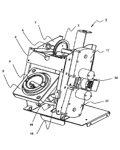
FIG. 1 is an isometric view of the automated brewing mechanism of this
invention shown in a position to accept a selected beverage carton or capsule
prior to initiation of a brewing cycle or process;
FIG. 2 is a side view of the brewing mechanism, showing its starting
position before the brew cycle and also the position after the last brew cycle
where the cartridge has been during which procedure the cartridge has been
ejected into a rearwardly located waste bin;
FIG. 3 shows a side view of the brewing mechanism after a brew button
has been activated, where the holder for the capsule is presented at the front
loading position ready to accept a beverage capsule from the user of the
machine;
FIG. 4 provides a side view of the position of the brewing mechanism after
the user has inserted a beverage capsule into its holder and has confirmed the
selection of the drink desired, with the lower brew chamber then moving the
holder and its capsule into an angular position which aligns it with the
mechanism
of the upper brew chamber for this machine;
FIG. 5 shows the position of the brewing mechanism once the lower motor
is turned off into a stop pin position, and the upper motor drives the upper
brew
chamber down until it senses that the upper chamber has bottomed out on the
lower brew chamber, at which time the capsule is initially pierced first by
the
upper needle, and then subsequently by the lower needle, in preparation for a
brewing process;
FIG. 6 shows the position of the brewing mechanism after a brewing cycle
or routine has been completed, and the upper motor reverses direction and
returns to its upper position, separating the spent capsule from the upper and
lower needles;
FIG. 7 shows the brewing mechanism in position where the lower motor
now rotates in a reverse direction driving the capsule ejection arm along a
cam
surface which lifts the capsule up and out of its holder and thereby
depositing the
spent capsule into a waste tray and bin;
D.N. 8246 9
Reg. Pat. App.
January 28, 2015
Newco Enterprises, Inc./cc
CA 02919031 2016-01-26
FIG. 8 shows the brewing mechanism where its lower brew chamber
continues its reverse travel until it is in its initial home position, at
which time the
motor turns off, and the brew mechanism is back where it awaits a signal to
start
another brew routine or cycle;
FIG. 9 depicts the brewing mechanism in a cutaway view where the lower
brew mechanism is in the correct position to brew, and the upper mechanism is
ready to start its downward travel to begin the piercing sequence of a brew
cycle;
FIG. 10 provides a sectional side view of the brewing mechanism
disclosing its support springs which hold the capsule in position while
piercing the
top of the capsule, and then under the force of the springs lowering the
pierced
capsule to attain a subsequent piercing by the lower needle;
FIG. 11 shows the brewing mechanism where the downward force of the
upper drive motor continues to drive the capsule downwardly, as stated, and
the
springs are forced to compress, to achieve a piercing by the lower needle of
the
bottom of the capsule;
FIG. 12 shows the spring mechanism that functions as an ejection arm for
forcing the spent capsule from its holder and into the waste collecting bin;
and
FIG. 13 provides the brewing mechanism similar to that shown in FIG. 9,
but taken from an opposite side view, in the processing of brewing, where its
upper needle has already pierced the top of the capsule, in preparation for
completion of a brewing cycle.
DESCRIPTION OF THE PREFERRED EMBODIMENT
In referring to the drawings, FIG. 1 is an illustrational view of the brewing
mechanism 1 as shown in a position to except a beverage cup, cartridge or
capsule prior to the brewing process, and to initiate the same. Generally,
FIG. 1
is an illustration of the brewing mechanism 1. The system includes an upper
drive cam 2 that moves an upper drive shaft 6 as when driven up or down by the
reversible gear motor 17, controlling the positioning of the upper brew
chamber
D.N. 8246 10
Reg. Pat. App.
January 28, 2015
Newco Enterprises, Inc./cc
CA 02919031 2016-01-26
3. The mechanism further includes a lower brew chamber 5, including a housing
to accept a beverage cartridge or capsule, as at 4, which is moved into
various
positions by the lower drive shaft 19, as shown, in this figure, in a forward
most
position only limited by its stop bracket 18. The position of the brewing
mechanism as shown in FIG. 1 is to accept a beverage cartridge prior to the
brewing process.
As disclosed in FIG. 2, therein is shown the starting position before the
brew cycle and also the position after the last brew cycle where the cartridge
has
been ejected into a waste bin (not shown). The position of both the upper and
lower brew chambers is determined by the rotation of the motor drive shafts
controlled by the two reversing dc drive motors, as explained. The upper brew
chamber movement is up and down as determined by its cam position and the
lower chamber swings in a circular arc directly driven by the lower drive
motor.
This is also the position of the brew mechanism when there is a disruption in
a
-- brew cycle and the machine is powered off and then back on, the firmware in
the
coffee brewer will send the upper and lower chambers to their reverse motor or
home positions. At this point, the mechanism is at rest and will stay in this
position until a brewing cycle on the beverage brewer is activated.
In FIG. 2, it specifically shows a cutaway illustration of the brewing
mechanism assembly 1 in the "home" or ready position. The assembly 1 consists
of side support panels 7, which hold and align the upper brew chamber 3 and
the
lower brew chamber 5. The upper brew chamber 3 is driven up and down by the
drive cam 2, connected to the upper drive shaft 6. The drive shaft is
connected to
an ordinary dc gear motor 17, which is reversible by electronic signals, and
controlling software. The position of ejection arm 10 is determined by contact
with the ejection cams 15 located on either side of the lower brew chamber 5.
See FIG. 7. The sequence of the drink preparation process is initiated as
shown
in FIG. 3, depicting a cutaway view of the brewing mechanism 1, showing the
lower brew chamber 5 having been driven forwardly by gear motor 21 through
the efforts of the lower drive shaft 19, and is located in a brew loading
position as
shown in FIG. 1. A beverage cup or capsule 9 can now be placed into the spring
D.N. 8246 11
Reg. Pat. App.
January 28, 2015
Newco Enterprises, Inc./cc
CA 02919031 2016-01-26
loaded capsule housing 4. The drive cam 2 is in the uppermost position at this
time. A beverage selection is now initiated by the user of the machine which
initiates the machine control device to send a signal to the lower brew drive
motor 21, to reverse its direction and move the lower brew chamber 5.
Generally, FIG. 3, in the method of operation, shows the position after a
brew button has been activated from the front control of the coffee brewer,
and
the lower brew mechanism travels towards the front of the machine where
interference with the lower brew housing opens a spring loaded door and
presents the capsule holder in a front loading position which is in a position
to
accept a drink capsule to the user of the machine. The control board or
software
senses that the lower motor has reached the forward travel position and turns
off
the lower drive motor.
In referring to FIG. 4, this shows the position after the machine user has
inserted the beverage container into the holder and has confirmed selection of
the drink and the lower brew chamber moves into a position which aligns with
and is parallel to the upper brew chamber. The motor movement stops when the
control board senses an alignment pin which positions the lower brew chamber
in
the correct align with the upper chamber and shuts off the lower motor. FIG.
4, in
addition to FIG. 9, shows views of the brewing mechanism 1, where the lower
.. brew chamber 8 has been driven rearward by gear motor 21 through the
operations of its lower drive shaft 19, and sets up the upper housing into a
brewing position, the location of the lower brew chamber 5 determines by
energizing solenoid 20 that drives the solenoid stop pin 12 which intercepts
movement of the lower brew chamber 5. Once the electronic controls sense gear
motor 21 current rise due to a stall current, the control turns off the power
to the
lower gear motor 21. The lower brew chamber 5, capsule housing 4, and the
beverage capsule 9 are now in brew position aligning up in alignment with the
upper brew chamber 3, angled rearwardly, as can be noted in FIG. 2. FIG. 9
further shows the construction of the brew chamber piercing needle 8, the brew
.. chamber needle seal 11, the brew chamber outer seal 13, and the support
springs 14, which hold the beverage capsule 9 in position during these
multiple
D.N. 8246 12
Reg. Pat. App.
January 28, 2015
Newco Enterprises, Inc./cc
CA 02919031 2016-01-26
, .
piercing processes. The ejection arm 10 is shaped to accommodate the lift
spring
14 which helps lift the beverage cartridge 9 out of the capsule housing 4. The
lower venting probe 16 is mounted to lower brew chamber 5. A beverage
collecting funnel 22 is attached to the lower brew chamber 5.
FIG. 5 shows the position once the lower motor is turned off in the stop pin
position, the upper motor drives the upper brew chamber down until the control
board senses the upper chamber has bottomed out on the lower brew chamber.
During this movement the capsule is first pierced by the upper needle, and
subsequently by the lower needle. Compressed air is introduced into the
capsule
during the piercing process to aid rigidity to the capsule. The compressed air
may
be any acceptable gas, such as natural air, or even NO2, that can be used for
maintaining the structural integrity of the capsule during the piercing
process. As
such, the brew chambers are now in a position where hot water can be pumped
through the upper or inlet needle, through the capsule, and the drink can be
routed out of the lower needle into a drinking cup. Note that the lower
piercing
needle pierces the lowermost point of the held capsule, and in this position,
can
drain out the entire brewed beverage from the capsule during a brewing
operation, since the capsule, within its housing, is held in an angular
position
within the brewing device, during usage. Thus, the capsule 4 is located in an
angular alignment, as can be seen in FIG. 9, and the lower needle 16 pierces
at
the lowermost location of the angulated capsule, as can be understood.
More specifically, FIG. 5 is a cutaway view of the next sequential
movement of the brewing mechanism 1, showing the downward movement and
engagement of the upper brew chamber 3 being driven downwardly by the drive
cam 2. FIG. 10 shows a cross sectional view of the brew mechanism 1 in the
same position as further depicting the piercing sequence of the beverage
capsule
9 as the upper gear motor 17 energizes causing the drive cam to drive the
upper
brew chamber 3 downwardly towards the capsule housing 4. The support springs
14 enable the brew chamber piercing needle 8 to pierce the top of the beverage
capsule 9 prior to the capsule housing 4 coming into contact with the lower
brew
chamber 5, until upper chamber 3 is stopped by interference with the lower
brew
D.N. 8246 13
Reg. Pat. App.
January 28, 2015
Newco Enterprises, Inc./cc
CA 02919031 2016-01-26
chamber 5, sensed by the control board to effect a stall current from the de-
energized upper gear motor 17, locking the brew chamber 5 in a brewing
position. Solenoid pin 12 is de-energized and moves out of the path of the
lower
brew chamber 5. As stated, compressed air or other gases are introduced into
the capsule during the piercing process to add rigidity to the capsule. The
brewing process is now able to occur through the upper probe 11, and the lower
probe 16, as shown in FIG. 11, which is a cross sectional view of the brew
mechanism 1 which further depicts the piercing and venting of the beverage
capsule 9, during this sequence of operation. As the upper motor 17 continues
to
cause drive cam 2 to drive the upper brew chamber 3 towards the lower brew
chamber 5, the beverage capsule 9 is then driven down over the vent probe or
needle 16 as described for these FIGS. 5 and 11. The plurality of piercing
needles 8 and the vent probe 16 in this configuration allows a pumped liquid
beverage to flow through the beverage capsule 9, and collects in the beverage
collecting funnel 22 before exiting the vending machine and into a common
drinking cup.
FIG. 6 shows the position after the brewing routine has finished, the upper
motor reverses direction and returns to the upper position. Once the control
board senses the upper brew chamber is in the uppermost position, the motor
stops. The upper chamber is now in the home position.
More specifically, after the liquid beverage is dispensed, the beverage
capsule removal process initiates, as shown in this FIG. 6. FIG. 6 depicts the
brew mechanism 1 after the brewing process has been completed and the
control mechanism energizes the upper drive motor 17, and the drive cam 2,
lifting the upper brew chamber 3 until the end of upward travel is reached,
and
the control mechanism senses a stall current and shuts off power to the upper
gear motor 17. The electronic control device then energizes the lower gear
motor
21, and drives the lower brew chamber 5 towards the ejection cam 15 through
the lower drive shaft 19, which causes interference with the ejection arm 10,
causing the ejection arm 10 to rise in the capsule housing 4, which in turn
lifts the
beverage capsule 9 out of the capsule housing 4, as also noted in FIG. 7.
Further
D.N. 8246 14
Reg. Pat. App.
January 28, 2015
Newco Enterprises, Inc./cc
CA 02919031 2016-01-26
movement is shown in FIG. 8, after the brewing process has completed and the
lower gear motor 21 continues to drive the lower brew chamber 5 through the
ejection cam 15 via the lower drive shaft 19, causing further interference
with the
ejection arm 10, and causing the ejection arm 10 to expel the beverage capsule
9 out of the capsule housing 4.
FIG. 7 shows the position where the lower motor now rotates in a reverse
direction driving the capsule ejection arm along a cam surface which lifts the
capsule up and out of the capsule holder, depositing the capsule in a waste
tray.
The capsule ejection arm has a spring in the center to assist in the ejection
.. process of the spent capsule.
FIG. 8 shows the lower brew chamber as it continues its reverse travel,
until the circuit control board senses it is in a home position, when the
motor
turns off, and the brew mechanism is back where is awaits a signal to start
another brew routine.
FIG. 9 depicts a cutaway view of the mechanism where the lower brew
mechanism is in the correct position to brew, and the upper mechanism is ready
to start downward travel to begin the piercing sequence of the brewing cycle.
FIG. 10 depicts the support springs which hold the capsule in position,
while piercing the top of the capsule. The force of the springs is greater
than the
force that is necessary to pierce the top of the capsule, so that the upper
inlet
needle first pierces the capsule, and only after that, is the capsule driven
downwardly for piercing of its bottom.
FIG. 11 shows the downward force of the upper drive motor as it
continues to drive the capsule down, and the springs are forced to compress.
The lower needle then pierces the bottom lower portion of the capsule. The
control board senses the end of travel and begins the brewing cycle.
FIG. 12 depicts the capsule ejection arm with the spring assist attached.
This FIG. 12 is a detailed view of the ejection arm 10, fitted with a lift
spring 23, to
assist in expelling the beverage capsule 9 into a waste container.
As further noted, in FIG. 13, this furnishes an opposite side view of the
beverage brewing device from that as disclosed in FIG. 9. As noted, its
collection
D.N. 8246 15
Reg. Pat. App.
January 28, 2015
Newco Enterprises, Inc./cc
CA 02919031 2016-01-26
, .
funnel 22 embraces the beverage capsule 9, such that when the beverage is
brewed, it extends downwardly through the lower funnel tube 24, and conveys
the brewed beverage that enters the lower needle 16, into the conduit 25 for
deposit downwardly into a cup or other receiving receptacle that may have been
previously located within the vending machine, to receive the brewed beverage,
during its brewing operation.
In the method of operation of the brewing mechanism, as already briefly
referred to, the sequence of its operations may be as follows. Generally, in
FIG.
1, this shows the starting position before the brew cycle and also the
position
after the last brew cycle, where the cartridge has been ejected into a waste
bin.
The position of both the upper and lower brew chambers is determined by the
rotation of the motor drive shafts controlled by the reversing dc drive
motors. The
upper brew chamber movement is up and down as determined by a cam
position, and the lower chamber swings in a circular arc, directly driven by
the
lower drive motor. This is also the position of the brew mechanism when there
is
a disruption in a brew cycle and the machine is powered off, and then back on,
where the firmware in the coffee brewer will send the upper and lower chambers
to their reverse motors, or home positions. At this point the mechanism is at
rest
and will stay in this position until a brewing cycle on the coffee brewer is
activated.
As previously noted in FIG. 2, and in FIG. 3, this sequence of operation
occurs when a brew button, on the vending machine, has been activated from
the front control on the coffee brewer, and the lower brew mechanism travels
towards the front of its arc, and the machine where interference with the
lower
brew housing opens a spring loaded door and presents the capsule holder in a
front loading position which is in a position to accept a drink capsule to the
user
of the machine. The control board senses that the lower motor has reached the
forward travel position and turns off the lower drive motor.
FIG. 4 is the position of the mechanism in the brew position. The user will
have confirmed selection of the drink, and the lower brew chamber has moved
into a position which aligns and is parallel to, the inclined upper brew
chamber.
D.N. 8246 16
Reg. Pat. App.
January 28, 2015
Newco Enterprises, Inc./cc
CA 02919031 2016-01-26
The motor movement is stopped when the control board senses an alignment pin
which positions the lower brew chamber in the angular correct alignment with
the
upper chamber and shuts off the lower motor.
FIG. 5 shows the brew mechanism in brew position with the upper
chamber being driven downwardly. Once the lower motor is turned off in the
stop
pin position, the upper motor drives the upper brew chamber down until the
control board senses the upper chamber has bottomed out on the lower brew
chamber. During this movement the capsule is pierced first by the upper
needle,
and subsequently by the lower needle, generally as explained in FIGS. 9, 10,
and
11. The brew chambers are now in position where hot water can be pumped
through the capsule and the drink can be routed into a drinking cup. As
previously reviewed, just prior to the piercing process, air or other gas will
be
injected into the capsule to maintain its structural integrity during the
piercing
process.
FIG. 6 shows the brew mechanism after brewing. After the brewing routine
is complete, the upper motor reverses direction and returns to its upper
position.
Once the control board senses the upper brew chamber is in the upper most
position, the motor stops. The upper chamber is now back in its home position.
FIG. 7 shows the brew mechanism with the cam follower operated to eject
the spent capsule. The lower motor now rotates in a reverse direction driving
the
capsule ejection arm along a cam surface which lifts the capsule up and out of
the capsule holder, depositing the capsule into a waste tray or bin.
FIG. 8 shows the capsule being removed, and the brew mechanism
locating back to its home position. The lower brew chamber continues its
reverse
travel until the control board senses it is in the home position, and the
motor
turns off. The brew mechanism is back where it awaits a signal to start
another
brew routine.
FIG. 9 shows the entire brew mechanism before brewing. This provides a
cutaway view of the mechanism where the lower brew mechanism is in the
correct position to brew, the upper brew mechanism is ready to start downward
travel to begin the piercing sequence in preparation for a brew cycle.
D.N. 8246 17
Reg. Pat. App.
January 28, 2015
Newco Enterprises, Inc./cc
CA 02919031 2016-01-26
, .
In initiating the brew cycle, FIG. 10 shows the brew mechanism during
piercing of the top of the capsule through its inlet needle or probe. The
support
springs hold the capsule in position while piercing the top of the capsule.
The
force of the springs is greater than the force that is necessary to pierce the
top of
the capsule.
FIG. 11 shows the brew mechanism during subsequent piercing of the
bottom of the capsule. As the motor continues to drive the capsule down, and
the
springs 4 are forced to compress, the lower needle then pierces the bottom of
the
capsule, as noted at 16.
This provides a definition of the sequence of operations of the single cup
brewing mechanism of this invention. As stated, generally this brewing
mechanism is designed for incorporation within a more commercial type of
vending machine, where individual cups of a coffee, tea, or the like, can be
freshly brewed.
Variations or modifications to the subject matter of this invention may
occur to those skilled in the art upon review of the invention as described
herein.
Such variations, if within the spirit of this invention, are intended to be
encompassed within the scope of any claims to patent protection issuing
hereon.
The specific definition of the invention, and its depiction in the drawings,
and its
method of operation, are set forth for illustrative purposes only.
30
D.N. 8246 18
Reg. Pat. App.
January 28, 2015
Newco Enterprises, Inc./cc