Note: Descriptions are shown in the official language in which they were submitted.
CA 02919084 2016-07-21
SHEAR SPRING USEFUL FOR VEHICLE SUSPENSION
RELATED APPLICATIONS
This application claims priority to U.S. Patent Application No. 13/950,873,
filed July
25, 2013.
BACKGROUND
The present invention generally relates to vehicle suspensions. More
particularly, the
present invention relates to vehicle suspensions having springs. Single spring
rate suspensions
and variable spring rate suspensions for use in vocational or heavy haul truck
applications are
known. Single spring rate suspensions have a fixed spring rate that generally
must be set at a
level that produces a suspension with either a comfortable ride or a stiff
suspension exhibiting
adequate roll stability. As a result, either roll stability or ride quality is
compromised in single
spring rate suspensions, depending upon the selected spring rate.
Variable spring rate suspensions overcome this deficiency of single spring
rate
suspensions by providing for multiple spring rates during operation. As the
sprung load is
increased, the spring rate is correspondingly increased. An example of a
variable spring rate
elastomeric spring suspension for use in vocational or heavy haul truck
applications is shown
in U.S. Patent No. 6,585,286. That suspension utilizes bolster springs and
auxiliary springs to
achieve its variable spring rate.
The assignee of the present invention disclosed a vehicle suspension having
shear
springs and a load cushion with a continuously increasing spring rate in U.S.
Application No.
12/876,158 which is entitled "Suspension Assembly With Tie-Plate" and was
filed on
September 5, 2010, which is a continuation-in-part of U.S. Patent Application
No.
12/545,828, now U.S. Patent No. 8,052,166, which is entitled "Tie-plate and
frame hanger of
1
CA 02919084 2016-07-21
a suspension assembly" and was filed August 22, 2009, which is a continuation-
in-part of
U.S. Patent Application No. 12/334,195, now U.S. Patent No. 8,152,195,
entitled "Modular
Suspension System and Components Thereof' filed on December 12, 2008, and a
continuation-in-part of U.S. Patent Application No. 12/045,069, entitled
"Elastomeric Spring
Vehicle Suspension" filed on March 10, 2008, now U.S. Patent No. 7,926,836,
each of which
is assigned to Hendrickson USA, L.L.C. The present application includes
improvements and
advancements over the vehicle suspensions disclosed in the applications noted
above.
SUMMARY
In one aspect, there is provided a suspension for supporting a longitudinally
extending vehicle frame rail above an axle, comprising: a first frame
attachment portion
adapted for connection to the vehicle frame rail; a first spring module
attached to the first
frame attachment portion; the first spring module having an opening; a first
spring mount
positioned within the opening of the first spring module; a first shear spring
positioned
between a first side wall of the first spring mount and a first side wall of
the opening of the
first spring module; a second shear spring positioned between a second side
wall of the first
spring mount and a second side wall of the opening of the first spring module;
the first spring
mount comprising an inboard part and an outboard part separate from the
inboard part, a first
through-hole positioned in at least one of the inboard or the outboard parts
of the first spring
mount adapted to allow passage of a first connecting rod therethrough, wherein
the first
connecting rod connects the inboard part of the first spring mount together
with the outboard
part of the first spring mount, and wherein the first shear spring comprises
an upper plate
having a V-shaped upper surface and a flat lower surface thereby forming a
triangular cross
section, where the first shear spring is compressed between the first side
wall of the first
spring mount and the first side wall of the opening of the first spring
module, and wherein the
2
CA 02919084 2016-07-21
second shear spring comprises an upper plate having a V-shaped upper surface
and a flat
lower surface thereby forming a triangular cross section, where the second
shear spring is
compressed between the second side wall of the first spring mount and the
second side wall of
the opening of the first spring module.
In another aspect, there may be provided a suspension wherein the first shear
spring
is comprised of a base plate having a flat upper surface and an upper plate
having a V-
shaped upper surface opposite the base plate adapted to mate with a
corresponding V-
shaped surface positioned on a first side wall of the first spring mount,
wherein the upper
plate has a flat lower surface parallel to the flat upper surface of the base
plate, and wherein
the second shear spring is comprised of a base plate having a flat upper
surface and an upper
plate having a V-shaped upper surface opposite the base plate adapted to mate
with a
corresponding V-shaped surface positioned on a second side wall of the first
spring mount,
wherein the upper plate has a flat lower surface parallel to the flat upper
surface of the base
plate.
In another aspect, there is provided a shear spring comprising: a base plate
having a flat
upper surface; an upper plate having a V-shaped upper surface and a flat lower
surface
thereby forming a triangular cross section, with the V-shaped upper surface of
the upper plate
positioned opposite the base plate adapted to mate with a corresponding V-
shaped surface
positioned on a side wall of a spring mount, the upper plate having the flat
lower surface
parallel to the flat upper surface of the base plate, and an elastomeric
material positioned
between the flat upper surface of the base plate and the flat lower surface of
the upper plate.
The shear spring may also be configured where the upper plate has an apex that
is
located at a centerline drawn perpendicularly through a center of the upper
plate and the
base plate, and the shear spring may also be configured to have an
intermediate plate having
3
CA 02919084 2016-07-21
a flat upper surface and a flat lower surface that are parallel to the lower
surface of the upper
plate and to the upper surface of the base plate, where the compression and
shear strain in
each of the elastomer sections is equalized across an entire cross-section
thereof
BRIEF DESCRIPTION OF THE DRAWINGS
3a
CA 02919084 2016-01-22
WO 2015/012930
PCT/US2014/036366
Exemplary embodiments of the invention are described herein with reference to
the
drawings, wherein like parts are designated by like reference numerals, and
wherein:
Figure 1 is a perspective view of a vehicle suspension 50;
Figure 2 is a perspective view of vehicle suspension 50 shown in Figure 1;
Figure 3 is an elevation view of the vehicle suspension 50 shown in Figures 1
and 2;
Figure 4 is a perspective view of a frame hanger component of vehicle
suspension 50
shown in Figures 1-3;
Figure 5 is another perspective view of the frame hanger component of Figure
4;
Figure 6 is a perspective view of a saddle assembly shown in Figures 1-3;
Figure 7 is another perspective view of the saddle assembly shown in Figure 6;
Figure 8 is a perspective view of a portion of the saddle assembly shown in
Figures 6
and 7;
Figure 8A is another perspective view of the portion of the saddle assembly
shown in
Figures 6 and 7;
Figure 9 is a perspective view of a shear spring used in the vehicle
suspension shown
in Figures 1-3;
Figure 10 is an elevation view of the shear spring in Figure 9;
Figure 11 is another elevation view of shear spring shown in Figures 9 and 10;
Figure 12 is a plan view of the shear spring shown in Figure 9;
Figure 13 is another perspective view of shear spring shown in Figures 9-12;
Figure 14 is a perspective view of a load cushion used in the vehicle
suspension of
Figures 1-3;
Figure 15 is another perspective view of the load cushion of Figure 14;
Figure 16 is an elevation view of the load cushion of Figures 14 and 15;
Figure 17 is a plan view of the load cushion shown in Figures 14-16;
4
CA 02919084 2016-01-22
WO 2015/012930
PCT/US2014/036366
Figure 18 is another plan view of the load cushion shown in Figures 14-17;
Figure 19 is a perspective view of a load cushion;
Figure 20 is a perspective view of a load cushion;
Figure 21a is a top view of an inboard saddle and an outboard saddle prior to
being
drawn together by two connecting rods;
Figure 21b is a top view of the saddles in Figure 21a after they have been
drawn
together by the connecting rods;
Figure 22 is a view of the outboard side of vehicle suspension 50;
Figure 23 is a cross sectional top view of the vehicle suspension 50 of Figure
22 along
line 23-23 shown in Figure 22;
Figure 24 is a bottom view of the vehicle suspension 50 shown in Figures 2 and
3;
Figure 25a is an elevation view of the vehicle suspension 50 shown in Figures
2 and
3;
Figure 25b is another elevation view of the vehicle suspension 50 shown in
Figures 2
and 3;
Figure 26 is a view of an alternate embodiment showing vehicle suspension 450;
Figure 27 is a view of vehicle suspension 650;
Figure 28 is a view of an alternate vehicle suspension 550;
Figure 29 is a view of a spring mount;
Figure 30 is a perspective view of another example vehicle suspension;
Figure 31 is a perspective view of another example vehicle suspension;
Figure 32 is a load cushion having two load cushion retainers extending from
the
base;
Figure 33 is a perspective outboard view of vehicle suspension 50' which is a
modified version of vehicle suspension 50 shown in Figure 2;
5
CA 02919084 2016-01-22
WO 2015/012930
PCT/US2014/036366
Figure 34 is an outboard view of the vehicle suspension 50' shown in Figure
33;
Figure 35 is a perspective inboard view of vehicle suspension 50' shown in
Figures 33
and 34;
Figure 36 is an inboard view of the vehicle suspension 50' shown in Figure 35;
Figure 37 is a perspective view of a saddle assembly shown in Figures 33-36;
Figure 38 is another perspective view of the saddle assembly shown in Figure
37;
Figure 39 is a perspective view of a portion of the saddle assembly shown in
Figures
37 and 38;
Figure 39A is another perspective view of the portion of the saddle assembly
shown
in Figures 37 and 38;
Figure 40 is a perspective view of a shear spring shown in the vehicle
suspension 50'
shown in Figures 33-36;
Figure 41 is a side view of the shear spring shown in Figure 40;
Figure 42 is another side view of the shear spring shown in Figures 40 and 41;
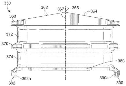
Figure 43 is a perspective view of a shear spring 350 that may be used in
suspension
50 or 50';
Figure 44 is an end view of shear spring 350 shown in Figure 43;
Figure 45 is a side view of the shear spring 350 shown in Figures 43 and 44;
Figure 46 is a cross-sectional side view of the spring 350 shown in Figure 45;
Figure 47 is a cross-sectional end view of the shear spring 350 taken along
the line
47-47 shown in Figure 43;
Figure 48 is a perspective view of vehicle suspension 1050; and
Figure 49 is a front view of the vehicle suspension 1050 shown in Figure 48.
6
CA 02919084 2016-01-22
WO 2015/012930
PCT/US2014/036366
DETAILED DESCRIPTION OF THE INVENTION
Figure 1 is a perspective view of a vehicle suspension 50 having a frame
attachment
portion 58 that is adapted for attachment to a vehicle frame or frame rail.
Vehicle suspension
50 is shown attached to a walking beam 78 positioned beneath the vehicle
suspension 50.
Also disclosed is a second vehicle suspension 50a having a frame attachment
portion 58a that
is adapted for attachment to a vehicle frame or frame rail on a side of the
vehicle opposite the
side to which vehicle suspension 50 is attachable to a vehicle frame or frame
rail. Vehicle
suspension 50a is shown attached to a walking beam 78a positioned beneath the
vehicle
suspension 50a. A cross tube 55 is attachable to vehicle suspensions 50 and
50a.
Vehicle suspension 50 is designed to support longitudinally extending vehicle
frame
rails (not shown) which can be of various types that are positioned above
laterally extending
vehicle axles. As will be appreciated by those skilled in the art, components
of vehicle
suspension 50 and the other suspensions described herein are duplicated on
each side of the
vehicle as shown in Figure 1. It will also be appreciated that vehicle wheels
may be mounted
to the ends of the vehicle axles in a known manner. Further, it will be
appreciated that the
vehicle frame rails may be connected by one or more vehicle frame cross
members.
Those skilled in the art will further understand that a suspension, arranged
in
accordance with the suspension 50 and the components thereof, alternatively
may be attached
to frame rails of a trailer (for example, a trailer that connects to a semi-
tractor). The frame
rails of a trailer may comprise frame rails such as those described above or
another type of
frame rail.
For purposes of this description, unless specifically described otherwise,
hereinafter,
"vehicle" refers to a vehicle or a trailer. In this way, for example, a
vehicle frame refers to a
vehicle frame or a trailer frame. Furthermore, for purposes of this
description, the left side of
a vehicle refers to a side of the vehicle on an observer's left-hand side when
the observer
7
CA 02919084 2016-01-22
WO 2015/012930
PCT/US2014/036366
faces the back of the vehicle, and the right side of the vehicle refers to a
side of the vehicle on
an observer's right-hand side when the observer faces the back of the vehicle.
Furthermore
still, for purposes of this description, "outboard" refers to a position
further away from a
center line, running from the front to the back of a vehicle, relative to
"inboard" which refers
to a position closer to that same center line.
Top edges 57 and 57a of frame attachments portions 58 and 58a, respectively,
have a
center portion that does not extend as far as the end portions of top edges 57
and 57a on both
sides of the center portions. As an example, those center portions may be
arranged in such
configurations so as to allow frame attachment portions 58 and 58a to be
attached to frame
lo rails that have features that would interfere with the attachment of
frame attachment portions
having center portions that extend to the same level as the end portions.
Figure 1 identifies walking beam ends 59 and 59a. In accordance with a first
embodiment, frame attachment portion 58 may be attached to a frame rail on the
left side of a
vehicle and the frame attachment portion 58a may be attached to a frame rail
on the right side
of the vehicle such that the front end of the vehicle is closer to walking
beam end 59 than it is
to walking beam end 59a. In accordance with a second embodiment, frame
attachment
portion 58 may be attached to a frame rail on the right side of the vehicle
and the frame
attachment portion 58a may be attached to a frame rail on the left side of the
vehicle, such
that the front end of the vehicle is closer to walking beam end 59a than it is
to walking beam
end 59.
Figure 2 is a perspective view of vehicle suspension 50 (the same suspension
shown
in Figure 1). Frame rail attachment holes 60 of frame attachment portion 58
are adapted for
attaching frame attachment portion 58 to a vehicle frame or frame rail (not
shown) using, for
example, connecting rods, such as mounting bolts. Vehicle suspension 50
includes gussets
8
CA 02919084 2016-01-22
WO 2015/012930
PCT/US2014/036366
62a-f extending perpendicularly from the frame rail attachment portion 58 to
provide
additional support and rigidity to vehicle suspension 50.
A spring module 70 is attached to frame rail attachment portion 58. Spring
module 70
includes an opening 64. Positioned within opening 64 are (i) at least a part
of a spring mount
66, (ii) at least a part of a first shear spring 72 positioned between a first
side wall of the
spring mount 66 and a side wall 80 of spring module 70, (iii) at least a part
of a second shear
spring 74 positioned between a second side wall of the spring mount 66 and a
second side
wall of spring module 70, and (iv) at least a part of a load cushion 76
positioned on top of
spring mount 66 and beneath the top wall 84 of spring module 70.
Similarly, but adjacent to spring module 70, a spring module 70a is attached
to frame
rail attachment portion 58. Spring module 70a includes an opening 64a.
Positioned within
opening 64a are (i) at least a part of a spring mount 66a, (ii) at least a
part of a shear spring
72a positioned between a first side wall of the spring mount 66a and a side
wall 80a (see
Figure 4) of spring module 70a, (iii) at least a part of a shear spring 74a
positioned between a
second side wall of the spring mount 66a and a side wall 82a of spring module
70, and (iv) at
least a part of a load cushion 76a positioned on top of spring mount 66a and
beneath the top
wall 84a (see Figure 3) of spring module 70a. As used herein, where it is
stated that a
component is positioned within the opening, that encompasses situations where
the
component is not entirely positioned within the opening. Thus, components
partially, but not
entirely, positioned within the opening are still positioned within the
opening within the
meaning of this specification.
Figure 3 shows an elevation view of vehicle suspension 50 (i.e., the same
suspension
shown in Figures 1 and 2). Spring module 70 is shown attached to frame rail
attachment
portion 58. Spring module 70 includes an opening 64. Positioned within at
least a portion of
opening 64 are (i) a spring mount 66, (ii) a shear spring 72 positioned
between a first side
9
CA 02919084 2016-01-22
WO 2015/012930
PCT/US2014/036366
wall of spring mount 66 and a first side wall 80 of opening 64, (iii) a shear
spring 74
positioned between a second side wall of spring mount 66 and a side wall of 82
of opening
64, and (iv) a load cushion 76 positioned on top of spring mount 66 and
beneath a top wall 84
of opening 64.
A second spring module 70a is positioned adjacent spring module 70 and is also
attached to frame rail attachment portion 58. Spring module 70a includes an
opening 64a.
Positioned within at least a portion of opening 64a are (i) a spring mount
66a, (ii) a third
shear spring 72a positioned between a first side wall of spring mount 66a and
a side wall 80a
of opening 64a, (iii) a fourth shear spring 74a positioned between a second
side wall of the
spring mount 66a and a second side wall 82a of opening 64a, and (iv) a load
cushion 76a
positioned on top of spring mount 66a and beneath a top wall 84a of opening
64a.
Figures 4 and 5 are perspective views of a frame hanger portion (or more
simply, a
"frame hanger") 100 that is a component of vehicle suspension 50 shown in
Figures 1-3.
Frame hanger 100 comprises frame attachment portion 58, gussets 62a-f, upper U-
plates 73
and 77, and lower U-plates 75 and 79. Each of U-plates 73, 75, 77, and 79 can
consist of a
single plate formed from a single flat plate, or alternatively, can be
fabricated from multiple
flat plates. Alternately, the U-plates can be cast. Further, the entire
opening 64 of spring
module 70, or portions thereof, could be cast as well.
Upper U-plate 77 and lower U-plate 79 define opening 64 of spring module 70.
Upper U-plate 77 includes flanges 77a and 77b and top wall 84. U-plate 79
includes side
walls 80 and 82 and bottom wall 86. Preferably, a distance 101 (shown in
Figure 5) between
the outer edges of flanges 77a and 77b is equal to or slightly less than a
distance 102 (shown
in Figure 5) between walls 80 and 82 such that upper U-plate 77 fits between
walls 80 and 82
and flanges 77a and 77b are operable as shear spring stops 84b and 84c for
shear springs 72
and 74, respectively.
CA 02919084 2016-01-22
WO 2015/012930
PCT/US2014/036366
Similarly, upper U-plate 73 and lower U-plate 75 define opening 64a of spring
module 70a. Upper U-plate 73 includes flanges 73a and 73b and top wall 84a. U-
plate 75
includes side walls 80a and 82a and bottom wall 86a. Preferably, a distance
103 (shown in
Figure 5) between the outer edges of flanges 73a and 73b is equal to or
slightly less than a
distance 104 (shown in Figure 5) between walls 80a and 82a such that upper U-
plate 73 fits
between walls 80a and 82a and flanges 73a and 73b are operable as shear spring
stops 84e
and 84d for shear springs 72a and 74a, respectively. Preferably, distance 101
equals distance
103, and distance 102 equals distance 104. Figure 4 illustrates side edges
110, 110a, 110b,
and 110c of side walls 80, 82, 80a, and 82a, respectively, and Figure 5
illustrates side edges
112, 112a, 112b, and 112c of side walls 80, 82, 80a, and 82a, respectively.
It should be noted the top wall 84 of the U-plate 77 and/or the top wall 84a
of U-plate
73 may include a dome-like configuration to control bulging of a progressive
spring rate load
cushion during loaded conditions thereby increasing the useful life of the
load cushion. The
load cushion may be an elastomeric progressive spring rate load cushion shaped
to resemble a
pyramid, and having a flattened top surface (see Figure 14 described below).
The top of the
load cushion nests within the dome-like configuration during loading. The dome-
like
configuration may be formed in top wall 84 or 84a by a stamping or punching
operation
where the top wall of the plate is plastically deformed. Alternately, a dome
could be cast or
forged into the top wall of the opening. In addition, a domed insert (e.g., a
cast or forged
dome insert) could be attached (e.g., by welding or bolting) to the top wall
to provide a top
wall with a dome-like configuration.
Lower U-plate 79 includes a weld-slot 81 through which a weld bead (not shown)
for
welding lower U-plate 79 to lower U-plate 75 can reside without extending
outside of weld-
slot 81. In accordance with an example embodiment, the weld bead within weld-
slot 81 may
be the only weld bead within opening 64, such that opening 64 includes no weld
beads that
11
CA 02919084 2016-01-22
WO 2015/012930
PCT/US2014/036366
can act as ramps upon which shear springs 72 or 74 can ride on to avoid shear
spring stops
84b or 84c, respectively.
Similarly, U-plate 75 includes a weld-slot (not shown) through which a weld
bead
(not shown) for welding lower U-plate 75 to lower U-plate 79 can reside
without extending
outside of the weld-slot within U-plate 75. In accordance with an example
embodiment, the
weld bead within the weld-slot within U-plate 75 may be the only weld bead
within opening
64a, such that opening 64a includes no weld beads that can act as ramps upon
which shear
springs 72a or 74a can ride on to avoid shear spring stops 84d or 84e,
respectively.
Preferably, the weld-slot within U-plate 75 has the same shape and orientation
as weld-slot
81 and is located closer to edge 110a of wall 86a than to edge 112b of wall
86a.
Figure 4 further illustrates a pocket 37 positioned on side wall 82a. Pocket
37 is
shown in dashed lines because pocket 37 is not required for use with shears
springs
configured as shear springs 72, 72a, 74, 74a, and 300. Rather pocket 37 might
be used with
shear springs having a flat base plate without outwardly extending flanges
(described below).
In accordance with embodiments in which pockets are used to retain shear
springs, such
pockets are typically located on the opposing side walls of the spring module.
Details
regarding pockets are shown and described in U.S. Patent No. 7,926,836.
It should be noted that while the above embodiments are shown constructed
using U-
shaped plates, U-shaped plates are not required. In fact, the top wall, bottom
wall, and first
and second side walls that define the opening could each be separate plates,
or otherwise
constructed without using U-shaped plates, although using U-shaped plates to
define the
opening is preferred in the above embodiments.
Figures 6 and 7 are perspective views of a saddle assembly 90 that is shown in
Figures 1-3 and that comprises an outboard saddle 120 and an inboard saddle
130. Figures 8
and 8A are perspective views of outboard saddle 120. In accordance with the
embodiments
12
CA 02919084 2016-01-22
WO 2015/012930
PCT/US2014/036366
described herein, inboard saddle 130 may be identical to outboard saddle 120.
Alternatively,
inboard saddle 130 may be identical to outboard saddle 130 except that the
mounting holes
(e.g., mounting holes 205, 205a) into which connecting rods 146 and 146a are
installed in one
of those saddles may be tapped holes and the mounting holes in the other
saddle may be
untapped holes.
Saddles 120, 130 each include upper and bottom portions. Each upper portion of
saddles 120, 130 includes two spring mount portions. Each of the two spring
mount portions
of saddle 120 interface to corresponding spring mount portions of saddle 130
to form
respective spring mounts 66 and 66a. The bottom portion of outboard saddle 120
includes a
bottom mount section 136, and the bottom portion of inboard saddle 130
includes a bottom
mount section 134. Those bottom mount sections may be conical, spherical, or
wedge
shaped, and may form a mechanical joint when attached to a walking beam as is
known in the
art. Furthermore, the bottom portions of outboard saddle 120 and inboard
saddle 130 may be
similar to the bottom portions of saddles disclosed in U.S. Patent No.
7,926,836.
As shown in one or more Figures 6, 7, 8, and 8A, the upper portion of outboard
saddle
120 is identified as upper portion 140, and the upper portion of inboard
saddle 130 is
identified as upper portion 142. As shown in Figure 8 and/or Figure 8A, upper
portion 142
includes a spring mount portion 143 and a spring mount portion 145. Spring
mount portion
143 includes spring mount side portions 143a and 143b and spring mount portion
interface
143f. Similarly, spring mount portion 145 includes spring mount side portions
145a and
145b and spring mount portion interface 145f. Each spring mount side portion
of upper
portions 140 and 142 includes a pair of flanges and a tapered surface.
As shown in Figure 8, spring mount side portion 143a incudes flanges 143c and
143d
and tapered surface 191a, and spring mount side portion 145b includes flanges
145c and 145d
and tapered surface 19 lb. As shown in Figure 8A, spring mount side portion
143b incudes
13
CA 02919084 2016-01-22
WO 2015/012930
PCT/US2014/036366
flanges 143e and 143g and tapered surface 191c, and spring mount side portion
145a includes
flanges 145e and 145g and tapered surface 191. Each flange on the spring mount
side
portions include a surface that is operable as a positive-stop to restrict a
shear spring from
moving beyond the positive-stop as the shear spring is moving in a direction
towards the
positive-stops. Examples of the shear spring positive-stops on the spring
mount side portions
shown in Figures 6 and 7 includes flange surfaces 173a, 173b, 173c, 173d,
173e, 173f, 173g,
173h, 173i, and 173j.
Upper portions 140, 142 of saddles 120, 130 include a number of significant
advantages over the saddles and saddle assemblies shown in U.S. Patent No.
7,926,836. As
one example, the upper portions 140, 142 of saddles 120, 130 are designed to
be drawn
together (e.g., drawn in contact with each other) by connecting rods 146 and
146a. In that
way, spring mount portion interface 143f is drawn into contact with a
corresponding spring
mount portion interface on upper portion 140 and spring mount portion
interface 145f is
drawn into contact with another corresponding spring mount portion interface
on upper
portion 140.
In accordance with this design, the upper portions 140, 142 may serve as
spring
mounts. In particular, the upper portions 140, 142 include first ends 150, 152
thereof that
together form first load cushion mounting surface 155 on first spring mount 66
that is adapted
to have a first load cushion mounted thereon. Similarly, upper portions 140,
142 also include
second ends 160, 162 thereof that together form second load cushion mounting
surface 165
on second spring mount 66a that is adapted to have a second load cushion
mounted thereon.
Of course, while two load cushion mounting surfaces are shown, only one, or
perhaps three
or more load cushion mounting surfaces could be provided on the upper portions
140, 142.
Thus, spring mounts 66 and 66a are integrally attached to the saddle, unlike
the saddle shown
in U.S. Patent 7,926,836. Indeed, spring mounts 66 and 66a are preferably
integrally formed
14
CA 02919084 2016-01-22
WO 2015/012930
PCT/US2014/036366
with the saddles 120 and 130, as shown in Figure 6. With this design, the need
for separate
spring mounts is eliminated. Of course, spring mounts integral with the saddle
are not
required and spring mounts that are separate from the saddle may be used for
particular
applications, as shown for example in Figure 27.
As mentioned above, the upper portions 140, 142 of the outboard saddle 120 and
inboard 130 are connected together. As discussed in greater detail below, a
threaded
connecting rod may be a bolt, screw, or other suitable fastener and may be
used to connect
the saddles together. As illustrated in Figure 6, one end of connecting rods
146 and 146a can
be seen indicating where the connection of the saddles may be accomplished.
Figure 7 further illustrates the threaded shank portions of connecting rods
146 and
146a. The threaded portion of the connecting rod 146 can be seen extending
through the
saddles 120, 130 and with nut 204 attached to the threaded portion so as to
connect the
saddles together. Similarly, the threaded portion of the connecting rod 146a
can be seen
extending through the saddles 120, 130 and with nut 204a attached to the
threaded portion so
as to connect the saddles together.
Depending on the application, the disclosed vehicle suspensions may not
utilize load
cushions on the top surface of the spring mounts, and thus the load cushion
mounting
surfaces 155 and 165 may not be necessary. However, even in the absence of
load cushion
mounting surfaces, with the design of the saddle assembly shown in Figures 6
and 7, the
upper portions 140, 142 may still serve as a spring mount. In particular, the
upper portions
140, 142 include first ends 150, 152 thereof that together form a first V-
shaped side wall 190
of spring mount 66, that is adapted to contact and compress a first shear
spring having a
corresponding V-shaped surface (not shown, but see below).
Similarly, upper portions 140, 142 also include second ends 160, 162 thereof
that
together form a second V-shaped side wall 190a of the spring mount 66a, that
is adapted to
CA 02919084 2016-01-22
WO 2015/012930
PCT/US2014/036366
contact and compress a second shear spring having a corresponding V-shaped top
surface
(also not shown, but see below). While V-shaped side walls 190 and 190a are
disclosed, the
saddles could be designed such that only ends 150 and 152 or ends 160 and 162
include a V-
shaped side wall. Again, with the design shown in Figure 6, the need for a
separate spring
mount to contact a shear spring is eliminated.
As described above, there are two openings (64 and 64a) in vehicle suspension
50.
The saddle assembly 90 also includes a third V-shaped wall 190b positioned
between side
walls 190 and 190a, as well as a fourth V-shaped wall 190c opposite from V-
shaped wall
190b and between side walls 190 and 190a. V-shaped walls 190b and 190c, along
with side
walls 82 and 80A, respectively, are also adapted to contact and compress
additional shear
springs having corresponding V-shaped surfaces (not shown, but see below).
Furthermore, upper portion 142 of inboard saddle 130 includes positive-stops
171a,
171c, 171e, and 171g. Similarly, upper portion 140 of outboard saddle 120
includes positive-
stops 171b, 171d, 171f, and 171h. Each of the foregoing positive-stops extends
upward
above load cushion mounting surfaces 155, 165, and is operable to prevent
vehicle
suspension 50 from having a longer than desired stroke. Those positive-stops
are most-likely
put into use when load cushions are not mounted to saddle assembly 90 or if
the load
cushion(s) mounted to saddle assembly 90 are compressed to a level below the
upper surfaces
of the positive-stops. During such use, the positive-stops can contact top
walls 84 and 84a so
as to limit the stroke of vehicle suspension 50. Furthermore still, as shown
in Figure 8 and/or
Figure 8A, upper portion 142 of inboard saddle 130 includes positive-stops
171w, 171x,
171y, and 171z. Each of the foregoing positive-stops, as well as similarly
positioned
positive-stops on upper portion 140 of outboard saddle 120, is operable to
prevent vehicle
suspension 50 from having a longer than desired stroke. The positive-stops
171w, 171x,
171y, and 171z are most-likely put into use during a rebound motion of vehicle
suspension
16
CA 02919084 2016-01-22
WO 2015/012930
PCT/US2014/036366
50. During such use, the positive-stops can contact bottom walls 86 and 86a so
as to limit the
stroke of vehicle suspension 50. Figure 8 and/or Figure 8A further illustrates
surface 155a
which provides one half of load cushion mounting surface 155 shown in Figures
6 and 7, and
surface 165a which provides one half of load cushion mounting surface 165
shown in Figures
6 and 7. Thus, surface 155a is part of an inboard part 66b of first spring
mount 66 shown in
Figures 6 and 7, and surface 165a is part of inboard part 66c of second spring
mount 66a
shown in Figures 6 and 7.
Figure 8 also illustrates tapered surface 191a that forms one half of V-shaped
wall
190a at end 162 of saddle assembly 90, and tapered surface 191b that forms one
half of V-
shaped wall 190b shown in Figures 6 and 7. Further, through-hole 205 is shown
in inboard
part 66b of first spring mount 66 which comprises half of spring mount 66, and
through-hole
205a is shown in inboard part 66c of second spring mount 66a which comprises
half of
second spring mount 66a. As can be seen from Figures 7 and 8, connecting rod
146 extends
through through-hole 205 and connecting rod 146a extends through through-hole
205a.
Figure 8A also illustrates tapered surface 191 that forms one half of V-shaped
wall
190 at end 152 of saddle assembly 90, and tapered surface 191c that forms one
half of V-
shaped wall 190c shown in Figures 6 and 7.
The frame hanger 100 of vehicle suspension 50 shown in Figures 4 and 5 may
comprise cast or fabricated metal or composite material, including iron,
steel, or aluminum.
As shown in Figure 4, frame hanger 100 is fabricated with gussets 62a-f, and
sheet steel may
be used to make frame attachment portion 58. Frame hanger 100 could also be
cast with any
suitable castable material. Similarly, the saddles may comprise cast or
fabricated metal or
composite material. Depending on the application, the metal may, for example,
be nodular
ductile iron (or more simply, ductile iron), steel, such as a high strength
low alloy steel, or
aluminum. Typically, high strength low alloy steels are a preferred material
to use for the
17
CA 02919084 2016-01-22
WO 2015/012930
PCT/US2014/036366
frame hanger and the saddle, although aluminum is often desired when weight
considerations
are of greater importance.
Figures 9 and 13 are perspective views of a shear spring 300, which is
sometimes
referred to as a V-spring. Any of the shear springs disclosed in the example
embodiments,
such as shear springs 72, 72a, 74, and 74a, may be arranged as shear spring
300. As shown in
Figure 9, shear spring 300 includes a base plate 302, a V-shaped plate 310,
and an
intermediate plate 312. V-shaped plate 310 results in shear spring 300 having
a V-shaped
wall 310a that is adapted to contact a corresponding V-shaped side wall of a
spring mount.
Shear spring 300 includes an elastomeric section 306 between base plate 302
and
intermediate plate 312, and an elastomeric section 308 between intermediate
plate 312 and V-
shaped plate 310. Alternatively, the shear spring could be made without one or
more of
plates 302, 310, and 312. For example, the shear spring could be all
elastomer, have a base
plate 302 without plates 310 and 312, have base plate 302 and plate 312 but no
intermediate
plate 312, etc. Furthermore, base plate 302 could also be V-shaped like plates
310 and 312
such that all three plates are V-shaped. In such a case, the side wall of the
opening contacting
base plate 302 could also have a corresponding V-shape. Moreover, the shear
spring 300 is
shown having the geometry of a preferred embodiment. It will be appreciated
that the base
plate 302 may not even include a plate as noted above. Further, the base or
base plate 302 of
the shear spring 300 could also be affixed to the side walls of the opening in
the spring
module using fasteners, bolts, etc. in a known and conventional manner. Thus,
the shear
spring is not required to have, but may have, the geometry shown in Figures 9-
13.
Figures 10 and 11 are elevational views of shear spring 300. Shear spring 300
has a
free-state vertical offset 301 between its end plates (i.e., base plate 302
and V-shaped plate
310). Preferably, the free-state vertical offset 301 is equal to half the
vertical travel of vehicle
suspension 50. This is done to minimize a couple induced in shear spring 300
by virtue of
18
CA 02919084 2016-01-22
WO 2015/012930
PCT/US2014/036366
the compression load acting on shear spring 300 applied at both end plates. A
couple is a
moment induced when equal and opposing forces are acting on a body but are not
collinear.
The effect of the couple on shear spring 300 is to induce rotation within the
spring that could
cause the spring to rotate within a spring module sufficiently enough to
relieve the shear
spring's compression and put the elastomeric sections (e.g., elastomeric
sections 306 and
308) into tension. Offsetting both endplates of shear spring 300 by a distance
equal to half of
the suspension's vertical travel results in couples at the fully stroked and
rebound conditions
being equal but opposite in direction (the magnitude of these couples is half
that of a spring
with no offset or an offset equal to that of the vertical travel of vehicle
suspension 50).
A shear spring is typically constructed from relatively flat first and second
end plates
with an elastomer connected between them. This spring will then have
compressive and
shear rates corresponding to the chosen material, cross-section, and thickness
of elastomer. If
one were to insert a third plate between the first and second end plates; such
that, it
subdivides the elastomer thickness into two separate, but not necessarily
equal, thickness; the
spring's compressive rate would increase while the shear rate would not be
affected. Because
the spring's plates are all relatively flat, the spring's shear rates in
mutually perpendicular
directions are the same.
If the spring has one or more plates with form; such that, the form confines
the
elastomer at least partially in one of the shear directions (use of V-plates
is one way); the
spring is no longer acting in pure shear in the confining direction. Rather,
the spring is acting
in a combination of shear and compression in the confining direction. The
result is the
confined shear direction having a higher effective shear rate than the
unconfined shear
direction. Just like above where the addition of plates to subdivide the
rubber increases the
compressive rate of the spring, the addition of formed plates will increase
the compressive
rate portion of the effective shear rate resulting in even higher effective
shear rates.
19
CA 02919084 2016-01-22
WO 2015/012930
PCT/US2014/036366
Figure 12 is a plan view of shear spring 300 comprising base plate 302, V-
shaped
plate 310, and intermediate plate 312. Base plate 302 includes a first flange
304 extending
from a first end thereof away from V-shaped plate 310 and a second flange 305
extending
from a second end thereof also away from V-shaped plate 310. Base plate 302 is
adapted to
contact a first side wall of a spring module opening of a vehicle suspension
(for example, side
wall 80 of opening 64 in the spring module of vehicle suspension 50).
Frictional forces
acting on shear spring 300, a side wall of a spring module opening, and a V-
shaped side wall
of a spring mount provide a primary means to prevent lateral movement of shear
spring 300.
The first flange 304 and the second flange 305 of base plate 302 are designed
to extend
M beyond first and second side edges of a side wall of a spring module
opening to secondarily
restrict lateral movement of shear spring 300 with respect to vehicle
suspension 50.
Intermediate plate 312 provides additional resistance to lateral shear forces
acting on
shear spring 300, such as lateral shear forces in a direction from flange 304
to flange 305 or
from flange 305 to flange 304. Intermediate plate 312 is shown as having a V-
shaped
configuration with the same angle as V-shaped plate 310. However, intermediate
plate 312
could have a larger or smaller angle for the V-shape as desired. Further,
intermediate plate
312 could be omitted or additional intermediate plates (e.g., intermediate V-
shaped plates)
could be included between V-shaped plate 310 and base plate 302.
Alternatively, an
intermediate plate (e.g., intermediate plate 312) could be a flat plate, like
the flat portion of
base plate 302 between flanges 304 and 306, and additional plates could be
added depending
on the application or desired performance.
The V-shaped plates 310 and 312 may be bent from straight plates. Since V-
shaped
plate 310 has a V-shape, V-shaped plate 310 has an angle that is less than 180
degrees.
Figure 12 illustrates an included angle 311 formed by V-shaped plate 310 and
an included
angle 313 formed by intermediate plate 312. In the embodiments in which
intermediate plate
CA 02919084 2016-01-22
WO 2015/012930
PCT/US2014/036366
312 has a V-shape, the included angles 311 and 313 are preferably the same
number of
degrees. The number of degrees ( ) of included angles 311 and 313 may be a
number of
degrees that fall within any of a plurality of angle ranges including, but not
limited to, the
angle ranges of (i) 90 to 179 , (ii) 90 to 170 , or (iii) 115 to 125 . In
accordance with that
latter range, the included angles 311 and 313 may, for example, be 1150, 116 ,
1170, 118 ,
119 , 120 , 121 , 122 , 123 , 124 , 125 or some non-whole number angle
between any two
of those listed angles.
In accordance with the disclosed embodiments, shear spring 300 may be
constructed
of elastomeric sections 306 and 308 bonded to plates 302, 310, and 312.
Elastomeric sections
306 and 308 may comprise an elastomeric material (i.e., an elastomer) such as
natural rubber,
synthetic rubber, styrene butadiene, synthetic polyisoprene, butyl rubber,
nitrile rubber,
ethylene propylene rubber, polyacrylic rubber, high-density polyethylene,
thermoplastic
elastomer, a thermoplastic olefin (TPO), urethane, polyurethane, a
thermoplastic
polyurethane (TPU), or some other type of elastomer. In this regard and in
particular,
elastomeric sections 306 and 308 may comprise an elastomer defined as American
Society of
Testing and Materials (ASTM) D2000 M4AA 717 A13 B13 C12 F17 Kll Z1 Z2. In this
case, Z1 represents natural rubber and Z2 represents a durometer selected to
achieve a desired
shear rate. The selected durometer may be based on a given predefined scale,
such as the
Shore A scale, the ASTM D2240 type A scale, or the ASTM D2240 type D scale. In
a
preferred embodiment, in accordance with the Shore A scale, Z2, for example,
is preferably
70 5. In another embodiment, in accordance with the Shore A scale, Z2 is,
for example,
within the range of 50 to 80. Other examples of Z2 and ranges for Z2 are also
possible.
In another respect, elastomeric sections 306 and 308 may comprise a
viscoelastomeric
material that (i) has elastic characteristics when the shear spring 300 is
under a load within a
given range and when that load is removed, and (ii) has non-elastic
characteristics (for
21
CA 02919084 2016-01-22
WO 2015/012930
PCT/US2014/036366
example, does not return to an original non-loaded shape) if the applied load
exceeds the
greatest load of the given range. The given range may extend from no load to a
maximum
expected load plus a given threshold. The given threshold accounts for
possible overloading
of shear spring 300. As an example, the viscoelastomeric material may comprise
amorphous
polymers, semi-crystalline polymers, and biopolymers. Other
examples of the
viscoelastomeric material are also possible.
In accordance with the example embodiments, elastomeric sections 306 and 308
may
also comprise one or more fillers. The filler(s) may optimize performance of
elastomeric
sections 306 and 308. The fillers may include, but are not limited to, wax,
oil, curing agents,
and/or carbon black. Such fillers may optimize performance by improving
durability and/or
tuning elastomeric sections 306 and 308 for a given shear load and/or a given
compressive
load applied to elastomeric sections 306 and 308. Improving durability through
the use of
fillers may include, for example, minimizing a temperature rise versus loading
characteristic
of elastomeric sections 306 and 308 and/or maximizing shape retention of
elastomeric
sections 306 and 308.
Shear spring 300 may be formed, for example, by inserting the plates 302, 310,
and
312 into a mold (not shown). The plates may each be coated with a coating
material. As an
example, the coating material may comprise a material comprising zinc and
phosphate,
modified with calcium. The coating material may have a coating weight of 200-
400
milligrams per square foot. Other examples of the coating material are also
possible. A
bonding agent may be applied to the coated plates for bonding the plates 302,
310, and 312 to
elastomeric sections 306, 308. As an example, the bonding agent may comprise
Chemlok0
manufactured by the Lord Corporation, Cary, North Carolina, USA. Other
examples of the
bonding agent are also possible. Applying the coating material and/or applying
the bonding
agent may occur prior to, during, and/or after insertion of the plates 302,
310, 312 into the
22
CA 02919084 2016-01-22
WO 2015/012930
PCT/US2014/036366
mold. After applying the coating material and the bonding agent, the
elastomeric material
(while in a pourable form) may be inserted into the mold to form the
elastomeric sections
306, 308.
In a preferred embodiment, any exposed portion of the plates 302, 310, and 312
(for
example, a portion of the plates not covered by the elastomeric material) is
protected against
corrosion by a means other than the elastomeric material. In other
embodiments, some
exposed portions of the plates 302, 310, and 312 (e.g., the edges of the
plates) may not be
protected against corrosion, whereas any other exposed portions of the plates
are protected
against corrosion.
The plates 302, 310, and 312 can be made of any of a variety of suitable
materials,
including, but not limited to, iron, steel, aluminum, plastic, a composite
material, or some
other material. The plates 302, 310, 312 may be fully, or at least
substantially, encapsulated
in elastomer to further enhance their corrosion resistance and friction at the
mating
suspension members. As an example, plates 302, 310, and 312 can comprise
plates having a
thickness between a range of 0.125 inches (3.175 mm) to 0.25 inches (6.35 mm).
In accordance with an example embodiment, the desired vertical shear rate of
the
shear spring 300 is approximately 615 N/mm (or approximately 3,500 pound force
per inch
(i.e., lbf/in)), and the initial compressive spring rate of the shear spring
300 is approximately
5,700 N/mm (or approximately 32,500 lbf/in).
Figures 14 and 15 are perspective views of an example load cushion 400 for use
in
vehicle suspension 50. Figure 16 is an elevation view of load cushion 400 and
Figures 17
and 18 are top and bottom plan views, respectively, of load cushion 400. Any
of the load
cushions disclosed in the example embodiments, such as load cushions 76 and
76a, may be
arranged as load cushion 400.
23
CA 02919084 2016-01-22
WO 2015/012930
PCT/US2014/036366
As shown in one or more of Figures 14, 15, and 16, load cushion 400 includes a
base
402, a load cushion portion 404, a mounting extension 406 with a mounting hole
407, and a
mounting extension 408. A load cushion retainer 410, integral with load
cushion 400,
extends from mounting extension 408. Load cushion portion 404 is positioned
between
mounting extensions 406 and 408 and, as shown in Figure 14, above base 402.
The load
cushion base 402 may comprise a metal plate that is either solid or includes
gaps or voids, or
may comprise elastomeric material or a combination thereof
Load cushion portion 404 may be designed to have at least one tapered wall,
and
generally, similarly shaped horizontal cross sections of different sizes
throughout. The size
change factor, or ratio of similitude, is a function of the taper of at least
one tapered wall.
The horizontal cross sections can be any geometric shape desired for
packaging, weight or
aesthetics. Additionally, or alternatively, the horizontal cross sections can
be selected to
obtain a desired vertical spring rate for load cushion 400.
Load cushion retainer 410 includes a load cushion retainer grip (or more
simply, a
grip) 414, a load cushion retainer shaft (or more simply, a shaft) 415, and a
load cushion
retainer disc (or more simply, a disc) 416. The shaft 415 extends between an
outer surface
402a (see, Figure 15) of base 402 and a retention surface 411 of disc 416.
Grip 414 extends
away from disc 416 from a portion of disc 416 opposite retention surface 411.
The diameters
of grip 414, shaft 415, and disc 416 may be different. For example, and as
shown in Figure
15, a diameter of shaft 415 is smaller than a diameter of disc 416, and a
diameter of grip 414
is generally smaller (although not necessarily smaller) than the diameters of
shaft 415 and
disc 416.
A length of shaft 415 may be selected with respect to a height of a saddle
assembly
recess, such as one of recesses 420 and 421 of saddle 120 or one of recesses
422 and 423 of
saddle 130. Typically, the length of shaft 415 is 10-15% less than the recess
height. This
24
CA 02919084 2016-01-22
WO 2015/012930
PCT/US2014/036366
allows the retainer to "clamp" itself into place. Furthermore, the diameter of
shaft 415 may
be selected with respect to a width of the saddle assembly recess. As an
example, the length
of shaft 415 may be selected to be slightly greater than the height of a
saddle assembly recess
and the diameter of shaft 415 may be selected to be slightly less than the
depth and/or the
width of the saddle assembly recess so that the shaft 415 can be positioned
within the saddle
assembly recess by hand.
Grip 414 may be used to pull or push shaft 415 into a saddle assembly recess,
as well
as to pull or push shaft 415 out of the saddle assembly recess. Load cushion
retainer 410 may
flex while grip 414 is pulled or pushed. A diameter of shaft 415, and thus the
width of the
saddle assembly recess, may be selected to be large enough such that load
cushion retainer
410 is not torn from outer surface 402a while a force to pull or push grip 414
is applied to
load cushion retainer 410.
Mounting load cushion 400 to load cushion mounting surface 155 or 165 of the
inboard and outboard saddles 120, 130 may include positioning shaft 415 into a
recess on a
load cushion mounting surface, such as either of recesses 420 and 423 on load
cushion
mounting surface 165 (shown in Figures 6 and 7), or either of recesses 421 and
422 on load
cushion mounting surface 155 (shown in Figures 6 and 7). After shaft 415 is
positioned
within a saddle assembly recess of either the inboard or outboard saddle, a
fastener, such as a
bolt, a screw, a cotter pin, a hitch pin, a pine-tree style pin, a clevis pin,
or some other type of
fastener or combination of fasteners, can be inserted into mounting hole 407
and into the
other saddle. In one respect, the other saddle may include a saddle assembly
recess as shown
in Figures 5 and 6. In another respect, the other saddle may include a tapped
or non-tapped
hole to which the fastener can be installed for retaining load cushion 404 at
mounting
extension 406. That tapped or non-tapped hole may be a through-hole.
Furthermore, the load
cushion retainer could also be positioned elsewhere on the load cushion.
CA 02919084 2016-01-22
WO 2015/012930
PCT/US2014/036366
Figure 19 is a perspective view illustrating an alternative load cushion 400a.
Any of
the load cushions disclosed in the example embodiments, such as load cushions
76 and 76a,
may be arranged as load cushion 400a. Load cushion 400a includes a base 402a,
a load
cushion portion 404a, a mounting extension 406a, and a mounting extension
408a. Base
402a, load cushion portion 404a, and mounting extension 408a are the same as
base 402, load
cushion portion 404, and mounting extension 408, respectively, of load cushion
400. Load
cushion portion 404a is positioned between mounting extensions 406a and 408a
and, as
shown in Figure 19, above base 402a.
A load cushion retainer 417, integral with load cushion 400a, extends from
mounting
extension 406a. Load cushion retainer 417 includes a load cushion retainer
grip (or more
simply, a grip) 418, a load cushion retainer shaft (or more simply, a shaft)
413, and a load
cushion retainer disc (or more simply, a disc) 412. Shaft 413 extends between
an outer
surface 403a of base 402a and a retention surface 419 of disc 412. Grip 418
extends away
from disc 412 from a portion of disc 412 opposite retention surface 419. The
foregoing
components of load cushion retainer 417 may be configured similar to like
named
components of load cushion retainer 410 shown in Figure 14.
Mounting load cushion 400a to load cushion mounting surface 155 or 165 of
inboard
and outboard saddles 120, 130 may include positioning shaft 415a into a recess
on a load
cushion mounting surface, such as either of recesses 421 and 423 on load
cushion mounting
surface 165 (shown in Figures 6 and 7), or either of recesses 420 and 422 on
load cushion
mounting surface 155 (shown in Figures 6 and 7). After shaft 415a is
positioned or while
shaft 415a is being positioned within a saddle assembly recess of either the
inboard or
outboard saddle, shaft 413 is positioned within another saddle assembly recess
on the same
load cushion mounting surface that includes the saddle assembly recess in
which shaft 415a
26
CA 02919084 2016-01-22
WO 2015/012930
PCT/US2014/036366
was or is being positioned. Grips 414a and 418 may be pushed or pulled for
enabling easier
installation of shafts 413 and 415a into respective recesses.
Figure 20 is a perspective view illustrating an alternative load cushion 400b.
Any of
the load cushions disclosed in the example embodiments, such as load cushions
76 and 76a,
may be arranged as load cushion 400b. Load cushion 400b includes a base 402b,
a load
cushion portion 404b, a mounting extension 406b, and a mounting extension
408b. Base
402b, load cushion portion 404b, and mounting extension 406b are the same as
base 402,
load cushion portion 404, and mounting extension 406, respectively, of load
cushion 400.
Load cushion portion 404b is positioned between mounting extensions 406b and
408b and, as
shown in Figure 20, above base 402b.
Mounting extension 406b includes a mounting hole 407b. Similarly, mounting
extension 408b includes a mounting hole 409. Mounting load cushion 400b to
load cushion
mounting surface 155 or 165 of inboard and outboard saddles 120, 130 may
include aligning
mounting holes 407b and 409 with a respective saddle assembly recess of either
of load
cushion mounting surface 155 or 165. A fastener separate from load cushion
400b, such as a
bolt, a screw, a cotter pin, or some other type of fastener, can be inserted
into mounting hole
407 and into a saddle assembly recess, such as one of saddle assembly recesses
420, 421,
422, or 423 shown in Figures 6 and 7. Alternatively, a saddle to which load
cushion 404b is
to be mounted may include a tapped or non-tapped hole to which the separate
fastener can be
installed for retaining load cushion 404 at mounting extension 406b. That
tapped or non-
tapped hole may be a through-hole. The opposite saddle may include a similarly
configured
tapped or non-tapped hole to which another separate fastener can be installed
for retaining
load cushion 404 at mounting extension 408b.
27
CA 02919084 2016-01-22
WO 2015/012930
PCT/US2014/036366
Alternately, as shown in Figure 32, load cushion 400c having base 402c may
include
a first load cushion retainer 430 comprising a first load cushion 430
extending from base
402c as well as a second load cushion retainer 440 also extending from base
402c.
Load cushions 400, 400a, 400b, and 400c preferably have a continuously
increasing
spring rate as an applied load increases and a continuously decreasing spring
rate as an
applied load decreases. Thus, the example vehicle suspensions, described
herein, that use
any of load cushions 400, 400a, 400b, and 400c can advantageously have a
continuously
increasing spring rate as an applied load increases and a continuously
decreasing spring rate
as an applied load decreases. Load cushions 400, 400a, 400b, and 400c act in
compression
and do not undergo tensile loading, so load cushions 400, 400a, 400b, and 400c
also have
increased fatigue life over other springs (for example, elastomer springs)
that are subjected to
such loading.
In accordance with example embodiments, each load cushion 400, 400a, 400b, and
400c is an elastomeric progressive spring rate load cushion shaped to resemble
a pyramid. In
one respect, the base and load cushion portion of load cushions 400, 400a,
400b, and 400c are
made of elastomer and do not include any plates or any bonding agents for
bonding plates to
elastomer. In another respect, the base of load cushions 400, 400a, 400b, and
400c may
include a plate (which can be referred to as a base plate) made of any of a
variety of suitable
materials, including, but not limited to, iron, steel, aluminum, plastic, and
a composite
material. As an example, the base plate can comprise a plate having a
thickness between a
range of 0.125 inches (3.175 mm) to 0.25 inches (6.35 mm). The base plate can
be
encapsulated in elastomer and/or bonded to the load cushion portion using a
bonding agent.
The base plate dimensions and shape can be varied to any dimension or shape
desired for
packaging, weight, and aesthetics. Preferably, each load cushion base is
dimensioned to (i)
match the top surface of a spring mount described herein, such as spring mount
66 or 66a, (ii)
28
CA 02919084 2016-01-22
WO 2015/012930
PCT/US2014/036366
locate mounting holes and/or load cushion retainer for securing the load
cushion base to the
spring mount, and (iii) minimize overall mass.
The size and dimensions of the elastomer used for the progressive spring rate
load
cushions 400, 400a, 400b, and 400c may be optimized for the vertical spring
rate
requirements. For the present application, the vertical spring rate for the
progressive spring
rate load cushions 400, 400a, 400b, and 400c continuously increases with
increasing load and
continuously decreases with decreasing load, defining a curvilinear shape with
no
discontinuities on a graph illustrating spring rate as a function of sprung
load.
Preferably, load cushion portion 404 has a shape closely resembling a pyramid
with a
flattened top surface, as shown. With this preferred shape, the vertical
spring rate for the load
cushion 400 linearly increases with increasing load and linearly decreases
with decreasing
load. In that regard, load cushion 400 is operable as a progressive spring
rate load cushion.
In one embodiment, the cross section of load cushion portion 404 adjacent base
402 is 120
millimeters (mm) by 150 mm, the cross section of the top surface of load
cushion portion 404
is 45 mm by 56 mm, the height of the load cushion portion 404 is 71 mm, and
the height of
base 402 is 9 mm. Other example dimensions of portions of load cushion 400 are
also
possible. For a given geometry, the spring rate of load cushion 400 may be
optimized by
varying the durometer of the elastomer. By varying the durometer, a family of
interchangeable progressive spring rate load cushions can be created.
Figures 21a and 21b are top views of inboard saddle 130 and outboard saddle
120.
Figure 21a shows inboard saddle 130 and outboard saddle 120 before a first
connecting rod
146 and a second connecting rod 146a are used to draw inboard saddle 130 and
outboard
saddle 120 together. Figure 21a shows connecting rod 146 extending through the
inboard
saddle and the outboard saddle with end 212 and nut 214 that will be tightened
against the
inboard saddle and outboard saddle to draw them together into contact.
Similarly Figure 21a
29
CA 02919084 2016-01-22
WO 2015/012930
PCT/US2014/036366
shows connecting rod 146a extending through inboard saddle 130 and outboard
saddle 120
with end 212a and nut 214a that will be tightened against the inboard saddle
and the outboard
saddle to draw them together into contact. Preferably, the ends 212 and 212a
of connecting
rods 146 and 146a are located within the outboard saddle such that the
opposing ends of those
connecting rods will not be in positions in which the opposing ends can make
contact with
tires or wheels that attach to axles connected to vehicle suspension 50.
Figures 21a and 21b illustrate shear spring 72 adjacent to first ends 150 and
152, and
shear spring 74a adjacent to second ends 160 and 162. Shear spring 72 has V-
shaped wall
310a adapted to contact the V-shaped side wall 190 of spring mount 66 (see
Figures 6 and 7),
wherein the shear spring 72 is positioned between side wall 80 of the opening
of the first
spring module and the V-shaped side wall 190. Prior to shear spring 72 being
placed under a
compression load by side wall 80 and V-shaped wall 190, the distance between V-
shaped
plate 310 of shear spring 72 and intermediate plate 312 of shear spring 72 is
denoted by the
letter "A," and the distance between intermediate plate 312 of shear spring 72
and base plate
302 of shear spring 72 is denoted by the letter "B."
Similarly, Figures 21a and 21b illustrate shear spring 74a adjacent to second
ends 160
and 162. Shear spring 74a has a V-shaped wall 310a adapted to contact the V-
shaped side
wall 190a of spring mount 66a (see Figures 6 and 7), wherein the shear spring
74a is
positioned between side wall 82a of the opening of the second spring module
and the V-
shaped side wall 190a. Prior to shear spring 74a being placed under a
compression load by
side wall 82a and V-shaped wall 190a, the distance between V-shaped plate 310
of shear
spring 74a and intermediate plate 312 of shear spring 74a is denoted by the
letter "C," and the
distance between intermediate plate 312 of shear spring 74a and base plate 302
of shear
spring 74a is denoted by the letter "D."
CA 02919084 2016-01-22
WO 2015/012930
PCT/US2014/036366
Figure 21b shows inboard saddle 130 and outboard saddle 120 after nuts 214 and
214a have been tightened onto connecting rods 146 and 146a to draw inboard
saddle 130 and
outboard saddle 120 into contact with each other. While tightening nuts 214
and 214a onto
connecting rods 210 and 210a together they also serve to cause (i) shear
spring 72 to be
compressed between V-shaped side wall 190 and side wall 80 of the opening of
the first
spring module 70, and (ii) shear spring 74a to be compressed between V-shaped
side wall
190a and side wall 82a of the opening of the second spring module 70a. The
tapered surfaces
of the V-shaped side wall 190 contact and compress shear spring 72 by a
wedging action in
which the elastomeric sections 306 and 308 of shear spring 72 are compressed.
Similarly, the
tapered surfaces of the V-shaped side wall 190a contact and compress shear
spring 74a by a
wedging action in which the elastomeric sections 306 and 308 of shear spring
74a are
compressed. As shown and described herein, the V-shaped surface of the shear
spring 72
contacts a corresponding V-shaped side wall 190 during compression, wherein
the surfaces
are preferably shown to be linear and in contact along nearly the entire
surface of the shear
spring. It will be noted that it is not necessary, although desirable, that
the entire V-shaped
surface of the shear spring 72 is in contact with the V-shaped wall 190 during
compression.
Moreover, it is possible that one or both of the contacting surfaces could be
curvilinear
provided that the surfaces provide a wedging action that serves to compress
the shear spring
72. For example, the surfaces of the V-shaped wall 190 and the shear spring 72
do not
necessarily need to be linear as shown in the above Figures, although linear
surfaces are
preferred.
As shown in Figure 21b, the elastomeric sections 306 and 308 of shear spring
72 are
compressed such that the distance between V-shaped plate 310 and intermediate
plate 312
(denoted as A') is less than distance A shown in Figure 21a, and the distance
between
intermediate plate 312 and base plate 302 (denoted as B') is less than
distance B shown in
31
CA 02919084 2016-01-22
WO 2015/012930
PCT/US2014/036366
Figure 21a. Similarly, the elastomeric sections 306 and 308 of shear spring
74a are
compressed such that the distance between V-shaped plate 310 and intermediate
plate 312
(denoted as C') is less than distance C shown in Figure 21a, and the distance
between
intermediate plate 312 and base plate 302 (denoted as D') is less than
distance D shown in
Figure 21a.
Thus, with reference to Figures 2 and 3, vehicle suspension 50 may be
assembled by
using a method including the steps of (i) providing a frame attachment portion
58 adapted for
connection to a vehicle frame rail having a spring module 70 attached to the
frame
attachment portion 58 wherein the spring module 70 has an opening 64 defined
by a top wall
84, a bottom wall 86, and first and second side walls 80, 82 of the spring
module, (ii)
positioning a first part 66b of a first spring mount 66 within the opening 64,
(iii) positioning a
first shear spring 72 between a first tapered surface of the first spring
mount 66 and a first
side wall 80 of the opening 64 of the first spring module 70, (iv) positioning
a second shear
spring 74a between a second tapered surface of the first spring mount 66 and
second side wall
82 of the opening 64 of the first spring module 70, (v) positioning a second
part of the first
spring mount 66 within the opening 64, (vi) placing a first threaded
connecting rod 164
through a through-hole in at least one of the first part of the first spring
mount 66 or the
second part of the first spring mount 66, and (vii) tightening the first
threaded connecting rod
164 to draw together the first part of the first spring mount 66 and the
second part of the first
spring mount 66, and to compress the first shear spring 72 between the first
side wall 190 of
the first spring mount 66 and the first side wall 80 of the opening 64 of the
first spring
module 70, and also to compress the second shear spring 74a between the second
side wall
190b of the first spring mount 66 and the second side wall 82 of the opening
64 of the first
spring module 70.
32
CA 02919084 2016-01-22
WO 2015/012930
PCT/US2014/036366
In this method of assembling a vehicle suspension, the need for separate
spring
mounts is eliminated. In addition, other prior art systems required the use of
a funnel and
difficult compression techniques of the shear spring to position the spring
mount and one or
more shear spring properly within the vehicle suspension. However, with this
method, these
problems have been eliminated because the shear springs are compressed by the
wedging
action of the V-shaped surfaces of the side walls of the spring mount and
corresponding V-
shaped side walls on the shear springs. The V-shaped surface of the spring
mount side walls
is formed by tightening the nut onto the connecting rod that passes through
the inboard and
outboard parts of the spring mount.
In addition, the disclosed vehicle suspension construction also provides
significant
advantages for servicing and disassembling the vehicle suspensions. For
example, if a shear
spring needs to be replaced, the serviceman can gradually decompress the shear
spring (e.g.,
reduce the compressive forces acting on the shear springs) within the vehicle
suspension by
loosening the nuts or connecting rods that were used do draw spring mount
portions together
to form a spring mount, in a staged and staggered method. The following
examples of staged
and staggered shear spring decompression methods are applicable to vehicle
suspension 50
using two connecting rods 146 and 146a.
First example of staged and staggered method to decompress shear springs:
Step Al ¨ Turn connecting rod 146 or nut 214 X number of degrees in a
direction that
causes nut 214 to move away from end 212.
Step A2 - Turn connecting rod 146a or nut 214a X number of degrees in a
direction
that causes nut 214a to move away from end 212a.
Step A3 ¨ Repeat steps Al and A2 until the shear springs retained by saddle
assembly
90 are decompressed.
Second example of staged and staggered method to decompress shear springs:
33
CA 02919084 2016-01-22
WO 2015/012930
PCT/US2014/036366
Step B1 ¨ Turn connecting rod 146 or nut 214 X number of degrees in a
direction that
causes nut 214 to move away from end 212.
Step B2 - Turn connecting rod 146a or nut 214a (X times 2) number of degrees
in a
direction that causes nut 214a to move away from end 212a.
Step B3 - Turn connecting rod 146 or nut 214 (X times 2) number of degrees in
a
direction that causes nut 214 to move away from end 212.
Step B4 ¨ Repeat steps B2 and B3 until the shear springs retained by saddle
assembly
90 are decompressed.
In the foregoing examples, X may equal 360 or some other number of degrees.
Other examples of staged and staggered method to decompress shear springs are
also
possible. Prior art systems posed more challenges because there was not a
simple way to
slowly ease the compressive forces on the shear springs when removing them
from the
vehicle suspensions.
Staged and staggered methods may also be used to place shear spring in
compression.
The following examples of staged and staggered shear spring compression
methods are
applicable to vehicle suspension 50 using two connecting rods 146 and 146a.
First example of staged and staggered method to compress shear springs:
Step Cl ¨ Turn connecting rod 146 or nut 214 X number of degrees in a
direction that
causes nut 214 to move towards end 212.
Step C2 - Turn connecting rod 146a or nut 214a X number of degrees in a
direction
that causes nut 214a to move towards end 212a.
Step C3 ¨ Repeat steps Cl and C2 until the shear springs retained by saddle
assembly
90 are compressed as desired.
Second example of staged and staggered method to compress shear springs:
34
CA 02919084 2016-01-22
WO 2015/012930
PCT/US2014/036366
Step D1 ¨ Turn connecting rod 146 or nut 214 X number of degrees in a
direction that
causes nut 214 to move towards end 212.
Step D2 - Turn connecting rod 146a or nut 214a (X times 2) number of degrees
in a
direction that causes nut 214a to move towards end 212a.
Step D3 - Turn connecting rod 146 or nut 214 (X times 2) number of degrees in
a
direction that causes nut 214 to move towards end 212.
Step D4 ¨ Repeat steps D2 and D3 until the shear springs retained by saddle
assembly
90 are compressed as desired.
In the foregoing examples, X may equal 360 or some other number of degrees.
Other examples of staged and staggered method to compress shear springs are
also possible.
In the example embodiments described herein, threaded connecting rods 146 and
146a
may be arranged in any one of a variety of configuration. Preferably, the
connecting rods are
M-20 x 1.5, class 10.9, bolts with sufficient threads to allow for each bolt
to pass through
both the inboard and outboard saddles and to engage corresponding nuts when
the shear
springs to be compressed via tightening of the bolts are in an uncompressed
state. A shank of
each bolt may, for example, be threaded from the bolt head to the shank end
opposite the bolt
head. Alternatively, each connecting rod could, for example, comprise a
different type of
bolt, or a screw, or some other suitable fastener. For instance, each
connecting rod could be a
rod with two threaded ends or a rod threaded from end to end. In this regard,
inboard and
outboard parts of the saddle could be drawn together to compress a set of
shear springs by
installing the threaded connecting rod into a hole tapped into one of the
inboard and outboard
parts of the saddle and using a nut on the opposite end of the connecting rod,
or by using a
respective nut threaded onto opposite ends of the threaded connecting rod.
Also, each
connecting rod could itself be round, square, or of some other geometric
shape.
CA 02919084 2016-01-22
WO 2015/012930
PCT/US2014/036366
Figure 22 is a view of the outboard side of vehicle suspension 50 having a
line 23-23
extending through shear spring 74a, first side wall 80a of the second opening
64a, and V-
shaped side wall 190a of spring mount 66a.
Figure 23 is a cross sectional top view of vehicle suspension 50 along line 23-
23
shown in Figure 22. In particular, shear spring 74a is shown in compression
between side
wall 80a and V-shaped side wall 190a of the second spring mount 66a. The V-
shaped wall
310a of shear spring 74a is in contact with V-shaped side wall 190a and shear
spring 74a is
wedged against side wall 80a. Base plate 302 of shear spring 74 abuts side
wall 80a.
Frictional forces acting on shear spring 74a, side wall 80a, and V-shaped side
wall 190a
provide a primary means to prevent lateral movement of shear spring 74a. Base
plate 302
includes flange 304 that extends from an end of base plate 302 in a direction
away from the
V-shaped plate 310. Similarly flange 305 extends from another end of base
plate 302 in a
direction away from V-shaped plate 310. In this manner, flanges 304 and 305
and side wall
80a can secondarily restrict lateral movement of the shear spring 74. For
example, side wall
112c can restrict lateral movement of shear spring 74 when flange 304 is in
contact with side
wall 112c, and side wall 110c can restrict lateral movement of shear spring 74
in an opposite
direction when flange 305 is in contact with side wall 110c.
Figure 24 is a bottom view of vehicle suspension 50 shown in Figures 2 and 3,
where
the flanges 304 and 305 of the shear springs are shown extending beyond the
spring modules
that comprise those shear springs. In particular, flanges 304 and 305 of shear
spring74a are
shown as extending beyond side edges 110c and 112c of side wall 82a, and
flanges 304 and
305 of shear spring 72 are shown as extending beyond side edges 110 and 112 of
side wall
80.
Figures 25a and 25b are elevational views of vehicle suspension 50 shown in
Figures
2 and 3.
36
CA 02919084 2016-01-22
WO 2015/012930
PCT/US2014/036366
Figure 26 illustrates an alternate embodiment showing vehicle suspension 450
haying
a frame attachment portion 458 attached to spring module 470, and haying a
single opening
464 defined by top wall 470a, side walls 470b and 470c, and bottom wall 470d.
Shown
positioned within opening 464 are first shear spring 72, second shear spring
74, and load
cushion 76 which are the same as the shear springs and load cushion described
in Figures 1-
25 above. Also shown is spring mount 466 which includes separate inboard and
outboard
spring mount portions. A connecting rod 465 is used to draw the inboard and
outboard spring
mount portions of spring mount 466 together and to compress shear springs 72
and 74
between spring mount 466 and side walls 470c and 470b, respectively, of spring
module 470.
Drawing the inboard and outboard spring mount portions form V-shaped walls
that abut the
V-shaped walls of shear springs 72 and 74.
Figure 27 illustrates a vehicle suspension 650 comprising a pair of frame
attachment
portions 451 and 452 that are attached to each other via a saddle 480. Frame
attachment
portions 451 and 452 include spring modules 453 and 455, respectively.
Spring module 453 includes a pair of shear springs 300 (as described above)
that are
retained in compression between opposing side walls of spring module 453 and a
spring
mount 459. Spring module 453 further includes a load cushion 454 that may be
configured
like any of load cushions 400, 400a, and 400b shown in one or more of Figures
14-20.
Spring mount 459 may be configured like spring mount 766, described below with
respect to
Figure 29, in that spring mount 459 may include a mounting bracket similar to
mounting
bracket 770 of spring mount 766. A threaded connecting rod 146e and nut 457
may be used
to attach saddle 480 to the mounting bracket of spring mount 459.
Similarly, spring module 455 includes a pair of shear springs 300 (as
described above)
that are retained in compression between opposing side walls of spring module
455 and a
spring mount 460. Spring module 455 further includes a load cushion 456 that
may be
37
CA 02919084 2016-01-22
WO 2015/012930
PCT/US2014/036366
configured like any of load cushions 400, 400a, and 400b shown in one or more
of Figures
14-20. Spring mount 460 may be configured like spring mount 766, described
below with
respect to Figure 29, in that spring mount 460 may include a mounting bracket
similar to the
mounting bracket 770 of spring mount 766. A threaded connecting rod 146f and
nut 458 may
be used to attach saddle 480 to the mounting bracket of spring mount 460.
Figure 28 illustrates an alternate vehicle suspension 550 having frame rail
attachment
portion 558 attached to first spring module 70 and second spring module 70a
having shear
springs, spring mounts and load cushions constructed in the same manner as
described above
with respect to Figures 1-25. Vehicle suspension 550 further includes a third
spring module
570 adjacent to the second spring module 70a, wherein the shear springs, load
cushion, and
spring mount with spring module 570 are also constructed in the same manner as
described
above with respect to Figures 1-25.
Vehicle suspension 550 further includes a saddle assembly 571 comprising two
separate saddles connected by connecting rods 146b, 146c, and 146d. Saddle
assembly 571
includes six V-shaped walls for compressing each of one of the six shear
springs contained
within vehicle suspension 550 as those V-shaped walls are formed by tightening
nuts onto
connecting rods 146b, 146c, and 146d. Loosening the nuts on those connecting
rods,
preferably in a staged and staggered manner, allows for removing the
compressive forces
placed on the six shear springs contained within vehicle suspension 550.
Figure 29 illustrates a spring mount 766 having a through-hole 205, a load
cushion
mounting surface 767, and V-shaped walls 768 and 769. Spring mount 766 is a
spring mount
that is not integrally connected to a saddle as is the case with spring mount
66 shown in
Figures 1-25. However, spring mount 766 does use a connecting rod to draw
together an
inboard part and an outboard part of the spring mount in the same manner as
shown in one or
more of Figures 1-25 and described above. Spring mount 766 may be used in
connection
38
CA 02919084 2016-01-22
WO 2015/012930
PCT/US2014/036366
with the shear springs and load cushion shown in one or more of Figures 1-25
and described
above. However, spring mount 766 is instead attached to a saddle using
mounting bracket
770. Thus, as is known in the art, the spring mount 766 may be attached to a
saddle, for
example, in the manner described in U.S. Patent 7,926,836.
Figure 30 illustrates vehicle suspension 850. Vehicle suspension 850 comprises
a
saddle assembly similar to the saddle assembly 90 of vehicle suspension 50,
shear springs
similar to the shear spring 300 described above, and load cushions similar to
any of the load
cushions 400, 400a, and 400b described above. Vehicle suspension 850 has some
notable
differences when compared to vehicle suspension 50. Those differences include:
(i) frame
rail attachment portions 858 and 858a have geometries that differ from the
geometries of
frame rail attachment portions 58 and 58a, (ii) the set of gussets including
gussets 854a, 854b,
854c, 854d, 854e, 854f, 854g, and 854h have geometries that differ from the
geometries of
set of gussets including gussets 62a, 62b, 62c, 62d, 62e, and 62f, and (iii)
vehicle suspension
850 includes frame hanger attachment portion strengtheners, such as
strengtheners 856a and
856b, on an inboard side of its frame rail attachment portions.
Furthermore, a filler plate 883 is attached between adjacent spring modules
70b and
70c of vehicle suspension 850, and a filler plate 884 is attached between
spring modules 70d
and 70e of vehicle suspension 850. Each side wall of a lower U-plate that is
adjacent to filler
plates 883 or 884 and that forms a part of an openings of spring modules 70b,
70c, 70d, or
70e may include 2 weld-slots through which weld beads for welding that side
wall to the
adjacent filler plate. Each of those weld-slots may have the size and shape of
weld-slot 81
described above.
Frame hanger attachment portion strengtheners are typically used in
embodiments in
which the distances between the tops of the spring module (e.g., tops 855,
855a) and the top
39
CA 02919084 2016-01-22
WO 2015/012930
PCT/US2014/036366
edge of the frame attachment portions (e.g., edges 857), and the distance
between spring
module tops 855c, 855d and the top edge 857a, exceed a given threshold
distance.
In Figure 30, the top edges 857 and 857a are straight, and walking beam ends
859 and
859a are identified. In accordance with a first embodiment in which vehicle
suspension 850
is installed in a vehicle, walking beam end 859 is closer to a front end of
the vehicle than
walking beam end 859a. In accordance with a second embodiment in which vehicle
suspension 850 is installed in a vehicle, walking beam end 859a is closer to
the front end of
the vehicle than walking beam end 859.
Figure 31 illustrates vehicle suspension 860, which is the same as vehicle
suspension
850 shown in Figure 30, except that frame rail attachment portions 868 and
868a have
geometries that differ from the geometries of frame rail attachment portions
858 and 858a.
Those geometries may differ, at least in part, because the geometries have
different patterns
and/or quantities of frame rail attachment holes between the frame hanger
attachment portion
strengtheners and the top edges of the frame hanger attachment portions.
In Figure 31, the top edges 867 and 867a are straight, and walking beam ends
859 and
859a are identified. In accordance with a first embodiment in which vehicle
suspension 860
is part of a vehicle, walking beam end 859 is closer to a front end of the
vehicle than walking
beam end 859a. In accordance with a second embodiment in which vehicle
suspension 860 is
part of a vehicle, walking beam end 859a is closer to the front end of the
vehicle than walking
beam end 859.
Figure 33 is a perspective outboard view of vehicle suspension 50' which is a
slightly
modified version of the vehicle suspension 50 shown in Figures 1-3. In Figures
33-36, the
same numerals will be used to identify the same or similar components of the
vehicle
suspension 50 in Figure 1, and different numerals or prime numbers will be
used to denote
CA 02919084 2016-01-22
WO 2015/012930
PCT/US2014/036366
differences between the vehicle suspension 50 shown in Figures 1-3 and the
vehicle
suspension 50' shown in Figures 33-36.
The vehicle suspension 50' shown in Figures 33-36 may be used as a substitute
for
the vehicle suspension 50 or vehicle suspension 50a shown in Figure 1.
Therefore, the
vehicle suspension 50' has a frame attachment 58 that is adapted for
attachment to a vehicle
frame or frame rail. Vehicle suspension 50' could be attached to walking beam
78 positioned
beneath the vehicle suspension 50 in Figure 1. In addition, vehicle suspension
50' could also
be substituted for vehicle suspension 50a as it is adapted for attachment to a
vehicle frame or
frame rail on a side of the vehicle opposite the side to which vehicle
suspension 50 is
lo attachable to a vehicle frame or frame rail, with the term vehicle
including a motorized
vehicle or trailer.
Vehicle suspension 50' includes frame rail attachment holes 60 of frame
attachment
portion 58 that are adapted for attaching frame attachment portion 58 to a
vehicle frame or
frame rail (not shown) using, for example, connecting rods, such as mounting
bolts. Vehicle
suspension 50' includes gussets 62a-f extending perpendicularly from the frame
rail
attachment portion 58 to provide additional support and rigidity to vehicle
suspension 50'.
A spring module 70 is attached to frame rail attachment portion 58. Spring
module 70
includes an opening 64. Positioned within opening 64 are (i) at least a part
of a spring mount
66', (ii) at least a part of a first shear spring 72' positioned between a
first side wall of the
spring mount 66' and a side wall 80 of spring module 70, (iii) at least a part
of a second shear
spring 74' positioned between a second side wall of the spring mount 66' and a
second side
wall 82 of spring module 70, and (iv) at least a part of a load cushion 76
positioned on top of
spring mount 66' and beneath the top wall 84 of spring module 70.
41
CA 02919084 2016-01-22
WO 2015/012930
PCT/US2014/036366
Similarly, but adjacent to spring module 70, a spring module 70a is attached
to frame
rail attachment portion 58. Spring module 70a includes an opening 64a.
Positioned within
opening 64a are (i) at least a part of a spring mount 66a', (ii) at least a
part of a shear spring
72a' positioned between a first side wall of the spring mount 66a' and a side
wall 80a of
spring module 70a, (iii) at least a part of a shear spring 74a' positioned
between a second side
wall of the spring mount 66a' and a side wall 82a of spring module 70a, and
(iv) at least a
part of a load cushion 76a positioned on top of spring mount 66a' and beneath
the top wall
84a of spring module 70a.
Vehicle suspension 50' shown in Figure 33 further includes a through-hole 910
and a
through-hole 910a that extend through both the outboard saddle 120' and
inboard saddle 130'
of saddle assembly 90'. The upper portions of the outboard saddle 120' and
inboard saddle
130' are connected together and form spring mounts 66' and 66a'. The outboard
saddle 120'
and the inboard saddle 130' may be drawn together in the same manner described
above in
the description of Figures 21a and 21b using threaded rods 146 and 146a shown
in Figure 6.
The threaded rods may be a bolt, screw, or other suitable fastener and may be
used to connect
the saddles together. Alternately, the outboard saddle 120' and inboard saddle
130' may be
drawn together using a press, such as a pneumatic or hydraulic press, or
weighted device.
Once the outboard saddle 120' and inboard saddle 130' are drawn together and
connected by threaded rods 146 and 146a, then connecting rods 922 and 924
which are
positioned on the sides of through hole 910 are used to hold the inboard and
outboard
portions of spring mount 66' together, and connecting rods 922a and 924a which
are
positioned on the sides of through hole 910a are used to hold the inboard and
outboard
portions of spring mount 66a' together. Connecting rods 922, 924, and 922a and
924a are
shown in Figure 33-36 as threaded bolts that extend all the way through the
outboard saddle
120' and the inboard saddle 130'. Nuts are used on the inboard side of the
saddle assembly
42
CA 02919084 2016-01-22
WO 2015/012930
PCT/US2014/036366
90'; however, the nuts could also be used on the outboard side of the saddle
assembly 90'. In
addition, connecting rods 922, 924, and 922a and 924a could also extend
through either
outboard saddle 120' or inboard saddle 130' and thread into a tapped hole in
the other saddle,
and therefore do not need to extend through both outboard saddle 120' and
inboard saddle
130'.
Furthermore, the connecting rods 922, 924, and 922a and 924a are shown as
threaded
in Figures 33-36, but are not required to be. For example, the connecting rods
922, 924, and
922a and 924a could comprise a non-threaded rod held in place by a cotter pin
in a manner
similar to rod 63 that holds load cushion 76 in position on spring mount 66'
with cotter pin 65
or rod 63a that holds load cushion 76a in position on spring mount 66a' with
cotter pin 65a.
Moreover, connecting rods are not required to have round cross-section, but
the connecting
rods could also have an oval, square, rectangular, polygonal, or other
geometric cross-section.
In a preferred embodiment the connecting rods may comprise an M20 fine pitch
fastener 10.9
class or grade.
As shown in Figures 33-36, after connecting rods 922, 924, and 922a and 924a
have
connected the outboard saddle 120' and 130' together, the threaded rods 146
and 146a used
to drawn the outboard saddle 120' and inboard saddle 130' together may be
removed.
Alternatively, the threaded rods 146 and 146a may remain in place. In
addition, while two
connecting rods are used in connection with a spring mount, it is possible to
include only one
connecting rod or additional connecting rods as desired, provided that they
provide sufficient
strength to hold outboard saddle 120' and inboard saddle 130' together during
operation.
An additional difference between vehicle suspension 50' and vehicle suspension
50 is
that vehicle suspension 50' includes gusset spacer 67 positioned between
gussets 62c and 62d
that provides additional strength and rigidity to the vehicle suspension 50'.
However, gusset
spacer 67 could also be used on vehicle suspension 50 if desired.
43
CA 02919084 2016-01-22
WO 2015/012930
PCT/US2014/036366
Figure 34 shows an outboard view of vehicle suspension 50' shown in Figure 33.
Spring module 70 is shown attached to frame rail attachment portion 58. Spring
module 70
includes an opening 64. Positioned within at least a portion of opening 64 are
(i) a spring
mount 66', (ii) a shear spring 72' positioned between a first side wall of
spring mount 66' and
a first side wall 80 of opening 64, (iii) a shear spring 74' positioned
between a second side
wall of spring mount 66' and a side wall of 82 of opening 64, and (iv) a load
cushion 76
positioned on top of spring mount 66' and beneath a top wall 84 of opening 64.
A second spring module 70a is positioned adjacent spring module 70 and is also
attached to frame rail attachment portion 58. Spring module 70a includes an
opening 64a.
Positioned within at least a portion of opening 64a are (i) a spring mount
66a', (ii) a third
shear spring 72a' positioned between a first side wall of spring mount 66a'
and a side wall
80a of opening 64a, (iii) a fourth shear spring 74a' positioned between a
second side wall of
the spring mount 66a' and a second side wall 82a of opening 64a, and (iv) a
load cushion 76a
positioned on top of spring mount 66a' and beneath a top wall 84a of opening
64a.
Connecting rods 922 and 924 are shown positioned on the sides of through hole
910 and are
used to hold the inboard and outboard portions of spring mount 66' together,
and connecting
rods 922a and 924a are shown positioned on the sides of through hole 910a and
are used to
hold the inboard and outboard portions of spring mount 66a' together.
Figure 35 is a perspective inboard view of vehicle suspension 50' shown in
Figures 33
and 34. Vehicle suspension 50' includes frame rail attachment holes 60 of
frame attachment
portion 58 that are adapted for attaching frame attachment portion 58 to a
vehicle frame or
frame rail (not shown) using, for example, connecting rods, such as mounting
bolts. Vehicle
suspension 50' includes gussets 62a-f extending perpendicularly from the frame
rail
attachment portion 58 to provide additional support and rigidity to vehicle
suspension 50'.
44
CA 02919084 2016-01-22
WO 2015/012930
PCT/US2014/036366
A spring module 70 is attached to frame rail attachment portion 58. Spring
module 70
includes an opening 64. Positioned within opening 64 are (i) at least a part
of a spring mount
66', (ii) at least a part of a first shear spring 72' positioned between a
first side wall of the
spring mount 66' and a side wall 80 of spring module 70, (iii) at least a part
of a second shear
spring 74' positioned between a second side wall of the spring mount 66' and a
second side
wall of spring module 70, and (iv) at least a part of a load cushion 76
positioned on top of
spring mount 66' and beneath the top wall 84 of spring module 70.
Similarly, but adjacent to spring module 70, a spring module 70a is attached
to frame
rail attachment portion 58. Spring module 70a includes an opening 64a.
Positioned within
opening 64a are (i) at least a part of a spring mount 66a', (ii) at least a
part of a shear spring
72a' positioned between a first side wall of the spring mount 66a' and a side
wall 80a of
spring module 70a, (iii) at least a part of a shear spring 74a' positioned
between a second side
wall of the spring mount 66a' and a side wall 82a of spring module 70a, and
(iv) at least a
part of a load cushion 76a positioned on top of spring mount 66a' and beneath
the top wall
84a of spring module 70a.
Vehicle suspension 50' shown in Figure 35 further includes a through-hole 910
and a
through-hole 910a that extend through both the outboard saddle 120' (shown in
Figure 33)
and inboard saddle 130' of saddle assembly 90'. The upper portions of the
outboard saddle
120' (shown in Figure 33) and inboard saddle 130' are connected together. The
outboard
saddle 120' and the inboard saddle 130' may be drawn together in the same
manner described
above in the description of Figures 21a and 21b using threaded rods 146 and
146a shown in
Figure 6. The threaded rod may be a bolt, screw, or other suitable fastener
and may be used
to connect the saddles together.
Once the outboard saddle 120' and inboard saddle 130' are drawn together and
connected by threaded rods 146 and 146a, then connecting rods 922 and 924
which are
CA 02919084 2016-01-22
WO 2015/012930
PCT/US2014/036366
positioned on the sides of through hole 910 are used to hold the inboard and
outboard
portions of spring mount 66' together, and connecting rods 922a and 924a which
are
positioned on the sides of through hole 910a are used to hold the inboard and
outboard
portions of spring mount 66a' together. Connecting rods 922, 924, and 922a and
924a are
shown in Figure 33-36 as threaded bolts that extend all the way through the
outboard saddle
120' and the inboard saddle 130'. Nuts 923 and 925, and 923a and 925a are
shown used on
the inboard side of the saddle assembly 90'; however, the nuts could also be
used on the
outboard side of the saddle assembly 90'. In addition, connecting rods 922,
924, and 922a
and 924a could also extend through either outboard saddle 120' or inboard
saddle 130' and
thread into a tapped hole in the other saddle, and therefore do not need to
extend through both
outboard saddle 120' and inboard saddle 130'.
Figure 36 shows an inboard view of vehicle suspension 50' shown in Figures 33-
35.
Spring module 70 is shown attached to frame rail attachment portion 58. Spring
module 70
includes an opening 64. Positioned within at least a portion of opening 64 are
(i) a spring
mount 66', (ii) a shear spring 72' positioned between a first side wall of
spring mount 66' and
a first side wall 80 of opening 64, (iii) a shear spring 74' positioned
between a second side
wall of spring mount 66' and a side wall of 82 of opening 64, and (iv) a load
cushion 76
positioned on top of spring mount 66' and beneath a top wall 84 of opening 64.
A second spring module 70a is positioned adjacent spring module 70 and is also
attached to frame rail attachment portion 58. Spring module 70a includes an
opening 64a.
Positioned within at least a portion of opening 64a are (i) a spring mount
66a', (ii) a third
shear spring 72a' positioned between a first side wall of spring mount 66a'
and a side wall
80a of opening 64a, (iii) a fourth shear spring 74a' positioned between a
second side wall of
the spring mount 66a' and a second side wall 82a of opening 64a, and (iv) a
load cushion 76a
positioned on top of spring mount 66a' and beneath a top wall 84a of opening
64a.
46
CA 02919084 2016-01-22
WO 2015/012930
PCT/US2014/036366
Connecting rods 922 and 924 are shown positioned on the sides of through hole
910 and are
used to hold the inboard and outboard portions of spring mount 66' together,
and connecting
rods 922a and 924a are shown positioned on the sides of through hole 910a and
are used to
hold the inboard and outboard portions of spring mount 66a' together.
Figures 37 and 38 are perspective views of a saddle assembly 90' that is shown
in
Figures 33-36 and that comprises an outboard saddle 120' and an inboard saddle
130'.
Figures 39 and 39A are perspective views of inboard saddle 130'. In accordance
with the
embodiments described herein, inboard saddle 130' may be identical to outboard
saddle 120'.
Alternatively, inboard saddle 130' may be identical to outboard saddle 120'
except that the
mounting holes 910 and 910a through which threaded rods 146 and 146a are
installed in one
of those saddles may be tapped holes and the mounting holes in the other
saddle may be
untapped holes. Similarly, holes for connecting rods 922 and 924, or 922a or
924a may also
extend all the way through, or may comprise tapped holes.
Saddles 120', 130' each include upper and bottom portions. Each upper portion
of
saddles 120', 130' includes two spring mount portions. Each of the two spring
mount
portions of saddle 120' interface to corresponding spring mount portions of
saddle 130' to
form respective spring mounts 66' and 66a'. The bottom portion of outboard
saddle 120'
includes a bottom mount section 136', and the bottom portion of inboard saddle
130 includes
a bottom mount section 134'. Those bottom mount sections may be conical,
spherical, or
wedge shaped, and may form a mechanical joint when attached to a walking beam
as is
known in the art. Furthermore, the bottom portions of outboard saddle 120' and
inboard
saddle 130' may be similar to the bottom portions of saddles disclosed in U.S.
Patent No.
7,926,836.
As shown in one or more of Figures 37, 38, 39, and 39A, the upper portion of
outboard saddle 120' is identified as upper portion 140', and the upper
portion of inboard
47
CA 02919084 2016-01-22
WO 2015/012930
PCT/US2014/036366
saddle 130' is identified as upper portion 142'. As shown in Figure 39 and/or
Figure 39A,
upper portion 142' includes a spring mount portion 143' and a spring mount
portion 145'.
Spring mount portion 143' includes spring mount side portions 143a' and 143b'
and spring
mount portion interface 143f. Similarly, spring mount portion 145' includes
spring mount
side portions 145a' and 145b' and spring mount portion interface 145f . Each
spring mount
side portion of upper portions 140' and 142' includes a pair of flanges and a
tapered surface.
As shown in Figure 39, spring mount side portion 143a' incudes flanges 143c'
and
143d' and tapered surface 191a', and spring mount side portion 145b' includes
flanges 145c'
and 145d' and tapered surface 191b'. As shown in Figure 39A, spring mount side
portion
143b' incudes flanges 143e' and 143g' and tapered surface 191c', and spring
mount side
portion 145a' includes flanges 145e' and 145g' and tapered surface 191'.
Upper portions 140', 142' of saddles 120', 130' include a number of
significant
advantages over the saddles and saddle assemblies shown in U.S. Patent No.
7,926,836. As
one example, the upper portions 140', 142' of saddles 120', 130' may be drawn
together
(e.g., drawn in contact with each other) by threaded rods 146 and 146a (shown
in Figures
21a and 2 lb). Of course, a press such as a pneumatic or hydraulic press could
be used to
draw the upper portions 140' and 142' together. In that way, spring mount
portion interface
143f is drawn into contact with a corresponding spring mount portion interface
on upper
portion 140' and spring mount portion interface 145f is drawn into contact
with another
corresponding spring mount portion interface on upper portion 140'.
In accordance with this design, the upper portions 140', 142' may serve as
spring
mounts. In particular, the upper portions 140', 142' include first ends 150',
152' thereof that
together form first load cushion mounting surface 155' on first spring mount
66' that is
adapted to have a first load cushion mounted thereon. Similarly, upper
portions 140', 142'
also include second ends 160', 162' thereof that together form second load
cushion mounting
48
CA 02919084 2016-01-22
WO 2015/012930
PCT/US2014/036366
surface 165' on second spring mount 66a' that is adapted to have a second load
cushion
mounted thereon. Of course, while two load cushion mounting surfaces are
shown, only one,
or perhaps three or more load cushion mounting surfaces could be provided on
the upper
portions 140', 142' in a manner similar to Figure 28. Thus, spring mounts 66'
and 66a' are
integrally attached to the saddle, unlike the saddle shown in U.S. Patent
7,926,836. Indeed,
spring mounts 66' and 66a' are preferably integrally formed with the saddles
120' and 130',
as shown in Figure 33. With this design, the need for separate spring mounts
is eliminated.
Of course, spring mounts integral with the saddle are not required and spring
mounts that are
separate from the saddle may be used for particular applications, as shown for
example in
Figure 27.
As mentioned above, the upper portions 140', 142' of the outboard saddle 120'
and
inboard 130' are connected together. As discussed in greater detail below, a
connecting rod
may be a bolt, screw, threaded or unthreaded, or other suitable fastener and
may be used to
connect the saddles together. As illustrated in Figures 37 and 38, connecting
rods 922 and
924, and connecting rods 922a, and 924a show where the connection of the
saddles may be
accomplished. Although two connecting rods 922 and 924 are shown for spring
mount 66', it
is possible to use only a single connecting rod, or additional connecting rods
as desired.
Figure 38 further illustrates the threaded shank portions of connecting rods
922 and
924, and 922a and 924a, with nuts 923 and 925, and nuts 923a and 925a attached
to connect
the saddles together. As noted above, the connecting rods do not need to be
threaded, but
could instead be a threadless rod held in place with a cotter pin or other
suitable holding
device.
Depending on the application, the disclosed vehicle suspension 50' may not
utilize
load cushions on the top surface of the spring mounts, and thus the load
cushion mounting
surfaces 155' and 165' may not be necessary. However, even in the absence of
load cushion
49
CA 02919084 2016-01-22
WO 2015/012930
PCT/US2014/036366
mounting surfaces, with the design of the saddle assembly 90' shown in Figures
38 and 39,
the upper portions 140', 142' may still serve as a spring mount. In
particular, the upper
portions 140', 142' include first ends 150', 152' thereof that together form a
first V-shaped
side wall 190' of spring mount 66', that is adapted to contact and compress a
first shear
spring having a corresponding V-shaped surface (not shown, but see below).
Similarly, upper portions 140', 142' also include second ends 160', 162'
thereof that
together form a second V-shaped side wall 190a' of the spring mount 66a', that
is adapted to
contact and compress a second shear spring having a corresponding V-shaped top
surface
(also not shown, but see below). While V-shaped side walls 190' and 190a' are
disclosed,
the saddles could be designed such that only ends 150' and 152' or ends 160'
and 162'
include a V-shaped side wall. Again, with the design shown in Figure 33, the
need for a
separate spring mount to contact a shear spring is eliminated.
As described above, there are two openings (64 and 64a) in vehicle suspension
50'.
The saddle assembly 90' also includes a third V-shaped wall 190b' positioned
between side
walls 190' and 190a', as well as a fourth V-shaped wall 190c' opposite from V-
shaped wall
190b' and between side walls 190' and 190a'. V-shaped walls 190b' and 190c',
along with
side walls 82 and 80a, respectively (of spring modules 70 and 70a shown in
Figures 33-36)
are also adapted to contact and compress additional shear springs having
corresponding V-
shaped surfaces (not shown, but see below).
Figure 39 and/or Figure 39A further illustrates surface 155a' which provides
one half
of load cushion mounting surface 155' shown in Figures 37 and 38, and surface
165a' which
provides one half of load cushion mounting surface 165' shown in Figures 37
and 38. Thus,
surface 155a' is part of an inboard part 66b' of first spring mount 66' shown
in Figures 37
and 38, and surface 165a' is part of inboard part 66c' of second spring mount
66a' shown in
Figures 37 and 38.
CA 02919084 2016-01-22
WO 2015/012930
PCT/US2014/036366
Figure 39 also illustrates tapered surface 191a' that forms one half of V-
shaped wall
190a' at end 162' of saddle assembly 90', and tapered surface 191b' that forms
one half of V-
shaped wall 190b' shown in Figures 37 and 38. Further, through-hole through-
holes 922b
and 924b are shown positioned about through-hole 910 that allow connecting
rods 922 and
924 to pass through, and through-holes 922d and 924d are shown positioned
about through-
hole 910a that allow connecting rods 922a and 924a to pass through.
Figure 39A also illustrates tapered surface 191' that forms one half of V-
shaped wall
190' at end 152' of saddle assembly 90', and tapered surface 191c' that forms
one half of V-
shaped wall 190c' shown in Figures 37 and 38.
Figure 40 is a perspective view of shear spring 300', which is sometimes
referred to
as a V-spring. The shear springs 72', 72a', 74', and 74a' shown in Figures 33-
36 may be
arranged as shear spring 300' shown in Figures 40-42. Shear spring 300' is
similar to shear
spring 300 shown in Figures 9-13 as it includes a base plate 302 and a V-
shaped plate 310.
However, shear spring 300' includes first intermediate plate 315 and second
intermediate
plate 317, which are shown as flat plates in Figures 40-42. However, it is
also possible to
include only a first intermediate plate that is flat, two intermediate plates
that are V-shaped,
or one V-shaped intermediate plate and one flat intermediate plate.
In shear spring 300', V-shaped plate 310 results in shear spring 300' having a
V-
shaped wall 310a that is adapted to contact a corresponding V-shaped side wall
of a spring
mount, although the surface of V-shaped wall 310a could be V-shaped even in
the absence of
V-shaped plate 310. Shear spring 300' includes an elastomeric section 306
between base
plate 302 and first intermediate plate 315, an elastomeric section 308 between
first
intermediate plate 315 and second intermediate plate 317, and an elastomeric
section 318
between second intermediate plate 317 and V-shaped plate 310. Of course, the
shear spring
could be made without one or more of plates 302, 315, 317, and 312. For
example, the shear
51
CA 02919084 2016-01-22
WO 2015/012930
PCT/US2014/036366
spring could be all elastomer, have a base plate 302 without intermediate
plates 315 and 317;
have base plate 302 and plate 310 but no intermediate plates, etc.
Furthermore, base plate
302 could also be V-shaped like plate 310, and all plates 302, 315, 317, and
310 could be V-
shaped. In such a case, the side wall of the opening contacting base plate 302
could also have
a corresponding V-shape.
Moreover, the shear spring 300' is shown having the geometry of a preferred
embodiment. It will be appreciated that the base plate 302 may not even
include a plate as
noted above. Further, the base or base plate 302 of the shear spring 300'
could also be
affixed to the side walls of the opening in the spring module using fasteners,
bolts, etc. in a
known and conventional manner. Thus, the shear spring is not required to have,
but may
have, the geometry shown in Figures 40-42.
Figure 41 is a plan view of shear spring 300' comprising base plate 302, V-
shaped
plate 310, first intermediate plate 315, and second intermediate plate 317.
Base plate 302
includes a first flange 304 extending from a first end thereof away from V-
shaped plate 310
and a second flange 305 extending from a second end thereof also away from V-
shaped plate
310. Base plate 302 is adapted to contact a first side wall of a spring module
opening of a
vehicle suspension (for example, side wall 80 of opening 64 in the spring
module of vehicle
suspension 50' in Figures 33-36). Frictional forces acting on shear spring
300', a side wall of
a spring module opening, and a V-shaped side wall of a spring mount provide a
primary
means to prevent lateral movement of shear spring 300'. The first flange 304
and the second
flange 305 of base plate 302 are designed to extend beyond first and second
side edges of a
side wall of a spring module opening to secondarily restrict lateral movement
of shear spring
300' with respect to vehicle suspension 50'.
Intermediate plates 315 and 317 provides additional resistance to lateral
forces acting
on shear spring 300', such as lateral forces in a direction from V-shaped
plate 310 to base
52
CA 02919084 2016-01-22
WO 2015/012930
PCT/US2014/036366
plate 302. Intermediate plates 315 and 317 are shown as flat plates parallel
to base plate 302.
However, intermediate plate 312 could have a larger or smaller angle for the V-
shape as
desired.
The V-shaped plate 310 may be bent from straight plates. Since V-shaped plate
310
has a V-shape, V-shaped plate 310 has an angle that is less than 180 degrees.
Figure 41
illustrates an included angle 311 formed by V-shaped plate 310. The included
angle 311 may
be a number of degrees that fall within any of a plurality of angle ranges
including, but not
limited to, the angle ranges of (i) 90 to 179 , (ii) 90 to 170 , or (iii)
115 to 125 . In
accordance with that latter range, the included angle 311 may, for example, be
1150, 116 ,
117 , 118 , 119 , 120 , 121 , 122 , 123 , 124 , 125 or some non-whole number
angle
between any two of those listed angles.
Figure 42 is aside view of shear spring 300'. Shear spring 300' has a free-
state
vertical offset 301' between its end plates (i.e., base plate 302 and V-shaped
plate 310).
Preferably, the free-state vertical offset 301 is equal to half the vertical
travel of vehicle
suspension 50' shown in Figures 33-36. This is done to minimize a couple
induced in shear
spring 300' by virtue of the compression load acting on shear spring 300'
applied at both end
plates. A couple is a moment induced when equal and opposing forces are acting
on a body
but are not collinear. The effect of the couple on shear spring 300' is to
induce rotation
within the spring that could cause the spring to rotate within a spring module
sufficiently
enough to relieve the shear spring's compression and put the elastomeric
sections (e.g.,
elastomeric sections 306, 308, and 318) into tension. Offsetting both
endplates of shear
spring 300' by a distance equal to half of the suspension's vertical travel
results in couples at
the fully stroked and rebound conditions being equal but opposite in direction
(the magnitude
of these couples is half that of a spring with no offset or an offset equal to
that of the vertical
travel of vehicle suspension 50').
53
CA 02919084 2016-01-22
WO 2015/012930
PCT/US2014/036366
In accordance with the disclosed embodiments shown in Figures 33-42, shear
spring
300' may be constructed of elastomeric sections 306, 308, and 318 bonded to
plates 302, 315,
317, and 310. Elastomeric sections 306, 308, and 318 may comprise an
elastomeric material
(i.e., an elastomer) such as natural rubber, synthetic rubber, styrene
butadiene, synthetic
polyisoprene, butyl rubber, nitrile rubber, ethylene propylene rubber,
polyacrylic rubber,
high-density polyethylene, thermoplastic elastomer, a thermoplastic olefin
(TPO), urethane,
polyurethane, a thermoplastic polyurethane (TPU), or some other type of
elastomer. In this
regard and in particular, elastomeric sections 306, 308, and 318 may comprise
an elastomer
defined as American Society of Testing and Materials (ASTM) D2000 M4AA 717 A13
B13
C12 F17 K1 1 Z1 Z2. In this case, Z1 represents natural rubber and Z2
represents a
durometer selected to achieve a desired shear rate. The selected durometer may
be based on
a given predefined scale, such as the Shore A scale, the ASTM D2240 type A
scale, or the
ASTM D2240 type D scale. In a preferred embodiment, in accordance with the
Shore A
scale, Z2, for example, is preferably 70 5. In another embodiment, in
accordance with the
Shore A scale, Z2 is, for example, within the range of 50 to 80. Other
examples of Z2 and
ranges for Z2 are also possible.
In another respect, elastomeric sections 306, 308, and 318 may comprise a
viscoelastomeric material that (i) has elastic characteristics when the shear
spring 300 is
under a load within a given range and when that load is removed, and (ii) has
non-elastic
characteristics (for example, does not return to an original non-loaded shape)
if the applied
load exceeds the greatest load of the given range. The given range may extend
from no load
to a maximum expected load plus a given threshold. The given threshold
accounts for
possible overloading of shear spring 300. As an example, the viscoelastomeric
material may
comprise amorphous polymers, semi-crystalline polymers, and biopolymers. Other
examples
of the viscoelastomeric material are also possible.
54
CA 02919084 2016-01-22
WO 2015/012930
PCT/US2014/036366
In accordance with the example embodiments, elastomeric sections 306, 308, and
318
may also comprise one or more fillers. The filler(s) may optimize performance
of
elastomeric sections 306, 308, and 318. The fillers may include, but are not
limited to, wax,
oil, curing agents, and/or carbon black. Such fillers may optimize performance
by improving
durability and/or tuning elastomeric sections 306, 308, and 318 for a given
shear load and/or
a given compressive load applied to elastomeric sections 306, 308, and 318.
Improving
durability through the use of fillers may include, for example, minimizing a
temperature rise
versus loading characteristic of elastomeric sections 306, 308, and 318 and/or
maximizing
shape retention of elastomeric sections 306, 308, and 318.
Shear spring 300' may be formed, for example, by inserting the plates 302,
315, 317,
and 310 into a mold (not shown). The plates may each be coated with a coating
material. As
an example, the coating material may comprise a material comprising zinc and
phosphate,
modified with calcium. The coating material may have a coating weight of 200-
400
milligrams per square foot. Other examples of the coating material are also
possible. A
bonding agent may be applied to the coated plates for bonding the plates 302,
315, 317, and
310 to elastomeric sections 306, 308, and 318. As an example, the bonding
agent may
comprise Chemlok0 manufactured by the Lord Corporation, Cary, North Carolina,
USA.
Other examples of the bonding agent are also possible. Applying the coating
material and/or
applying the bonding agent may occur prior to, during, and/or after insertion
of the plates
302, 315, 317, and 310 into the mold. After applying the coating material and
the bonding
agent, the elastomeric material (while in a pourable form) may be inserted
into the mold to
form the elastomeric sections 306, 308, and 318.
In a preferred embodiment, any exposed portion of the plates 302, 315, 317,
and 310
(for example, a portion of the plates not covered by the elastomeric material)
is protected
against corrosion by a means other than the elastomeric material. In other
embodiments,
CA 02919084 2016-01-22
WO 2015/012930
PCT/US2014/036366
some exposed portions of the plates 302, 315, 317, and 310, (e.g., the edges
of the plates)
may not be protected against corrosion, whereas any other exposed portions of
the plates are
protected against corrosion.
The plates 302, 315, 317, and 310 can be made of any of a variety of suitable
materials, including, but not limited to, iron, steel, aluminum, plastic, a
composite material,
or some other material. The plates 302, 315, 317, and 310 may be fully, or at
least
substantially, encapsulated in elastomer to further enhance their corrosion
resistance and
friction at the mating suspension members. As an example, plates 302, 315,
317, and 310 can
comprise plates having a thickness between a range of 0.125 inches (3.175 mm)
to 0.25
inches (6.35 mm).
The vehicle suspension 50' can be initially drawn together in the same manner
as the
method of assembly of vehicle suspension 50 described above. Therefore, with
reference to
Figures 33-36, vehicle suspension 50' may be assembled by using a method
including the
steps of (i) providing a frame attachment portion 58 adapted for connection to
a vehicle frame
rail having a spring module 70 attached to the frame attachment portion 58
wherein the
spring module 70 has an opening 64 defined by a top wall 84, a bottom wall 86,
and first and
second side walls 80, 82 of the spring module, (ii) positioning a first part
of a first spring
mount 66' within the opening 64, (iii) positioning a first shear spring 72'
between a first
tapered surface of the first spring mount 66' and a first side wall 80 of the
opening 64 of the
first spring module 70, (iv) positioning a second shear spring 74' between a
second tapered
surface of the first spring mount 66' and second side wall 82 of the opening
64 of the first
spring module 70, (v) positioning a second part of the first spring mount 66'
within the
opening 64, (vi) placing a first threaded connecting rod 164 (see Figures 21a
and 21b)
through a through-hole in at least one of the first part of the first spring
mount 66' or the
second part of the first spring mount 66', and (vii) tightening the first
threaded rod 146 (see
56
CA 02919084 2016-01-22
WO 2015/012930
PCT/US2014/036366
Figures 21a and 21b) to draw together the first part of the first spring mount
66' and the
second part of the first spring mount 66', and to compress the first shear
spring 72' between
the first side wall of the first spring mount 66' and the first side wall 80
of the opening 64 of
the first spring module 70, and also to compress the second shear spring 74'
between the
second side wall of the first spring mount 66' and the second side wall 82 of
the opening 64
of the first spring module 70. The shear springs 72a' and 74a' are compressed
between
spring mount 66a' and walls 80a and 82a in a similar manner using threaded rod
146a.
However, the method of assembly of vehicle suspension 50' differs from that of
vehicle suspension 50 in that the saddle assembly 90' includes additional
through holes for
connecting outboard saddle 120' and inboard saddle 130' using connecting rods
922 and 924,
as well as 922a and 924a. After the threaded rods 146 and 146a are used to
draw and
connects the outboard saddle together (as shown in Figures 2, 3, and 21a and
21b) and
described above, then connecting rods 922 and 924 positioned about through-
hole 910 are
used to further secure the outboard saddle 120' and inboard saddle 130'
together, and
connecting rods 922a and 924a positioned about through-hole 910a are used to
further secure
the outboard saddle 120' and inboard saddle 130' together. At this point, the
threaded rods
146 and 146a may be, but are not required to be, removed, leaving connecting
rods 922 and
924, and 922a and 924a securing outboard saddle 120' and inboard saddle 130'
together.
Figures 33-36 shows vehicle suspension 50' with threaded rods 146 and 146a
removed from
through-holes 910 and 910a of vehicle suspensions 50'.
The use of two connecting rods 922 and 924 for spring mount 66', and two
connecting rods 922a and 924a for spring mount 66a' may provide for additional
holding
strength that is greater than using a single threaded rod 146 or 146a for each
spring mount.
One benefit of using connecting rod 922 or 924 after threaded rod 146 has been
used
to draw the outboard saddle 120' together with inboard saddle 130' is that it
may be shorter
57
CA 02919084 2016-01-22
WO 2015/012930
PCT/US2014/036366
than threaded rod 146, as the length of connecting rod 922 or 924 need only be
long enough
for attachment of a nut or other securing device after the outboard saddle
120' and inboard
saddle 130' have been drawn together. By contrast, the threaded rod 146 must
be long
enough to extend through outboard saddle 130' and inboard saddle 120' before
they are
drawn together, resulting in a potentially undesirable protrusion of threaded
rod 146
extending from the vehicle suspension.
Moreover having two connecting rods in each spring mount provides a redundancy
in
the vehicle suspension, in that if one rod were to fail, the other connecting
rod would still
hold the outboard saddle 120' and inboard saddle 130' together. Where two
springs are used
with two connecting rods per spring mount, then there would be four connecting
rods holding
the outboard saddle 120' and inboard saddle 130' together. In this case, if
one of the
connecting rods failed, then there would still be three connecting rods
holding the outboard
saddle 120' and inboard saddle 130' together.
The walking beams used with the various example vehicle suspensions described
herein may be constructed in any of a variety of arrangements. In that regard,
the number of
and/or dimensions of various plates used to construct the walking beams may
vary between
the various walking beam arrangements. Furthermore, the walking beams attached
to the
each vehicle suspension may be retained to the vehicle suspension via various
components
such as, for example, a set of components comprising a saddle cap and threaded
connecting
rods or a set of components comprising a U-bolt and a pair of nuts.
Figures 43-47 are directed to shear spring 350, which includes an alternate
shear
spring design that may be used in vehicle suspension 50 shown in Figures 1-2,
and 22-26, and
vehicle suspension 50' shown in Figures 33-36. In particular, shear springs
72, 74, 72a, and
74a shown in Figures 1-2, and 22-26 may be arranged as shear spring 350 shown
in Figures
58
CA 02919084 2016-01-22
WO 2015/012930
PCT/US2014/036366
43-47, and shear springs 72', 74', 72a', and 74a' shown in Figures 33-36 may
be arranged as
shear spring 350 shown in Figures 43-47. Furthermore, shear spring 350 shown
in Figures
43-47 may also be used in vehicle suspension 1050 shown in Figures 48 and 49.
In
particular, in a preferred embodiment, shear springs 1072, 1074, 1072a, and
1074a shown in
suspension 1050 may be arranged as shear spring 350 as shown in Figures 43-47.
Figure 43 is a perspective view of shear spring 350 that is similar to shear
spring 300
shown in Figures 9-13 and shear spring 300' shown in Figures 40-42 as it
includes a base
plate 380 and a plate 360 with a V-shaped upper surface. Shear spring 350 also
includes a
first intermediate plate 370 which is shown as a flat plate in Figures 43-47.
However, in
other embodiments, it is also possible to include additional intermediate
plates, as desired. It
will be appreciated that the terms "upper" "lower" and "base" are used in the
specification
and claims only to provide relational references for the components of the
shear spring.
However, the terms "upper" "lower" and "base" in no way require that the shear
spring is
oriented in any particular manner in a vehicle suspension. In fact, it will be
appreciated that
shear springs shown in suspension 50, 50' and 1050 show the shear springs
positioned with
the base plate and upper surface of the shear spring are mounted in a
generally horizontal
orientation. Thus, the shear spring 350 may be oriented horizontally,
vertically, or
somewhere in between.
In shear spring 350, plate 360 has a V-shaped upper surface that results in
shear
spring 350 having a V-shaped outer surface comprising surfaces 362 and 364
that are adapted
to contact a corresponding V-shaped side wall of a spring mount. As used
herein, the term
"V-shaped" is to be broadly construed to cover two walls angled with respect
to one another,
that may or may not come together at a point. In other words, the apex of the
V-shaped
surface could be rounded or even flat. Chaplets 366 are shown on the upper
surface of plate
59
CA 02919084 2016-01-22
WO 2015/012930
PCT/US2014/036366
360 within surfaces 362 and 364 that are used during the molding process. In
addition, the
corners of plates 360, 370, and 380 are also exposed to facilitate the molding
process.
Figure 44 shows an end view of shear spring 350 shown in Figure 43, and Figure
47
shows a cross-sectional end view of shear spring 350 shown in Figure 43 taken
along line 47-
47. It will be appreciated that plate 360 has a flat bottom surface 361
positioned beneath
angled upper surfaces 363 and 373 of plate 360. In other words, plate 360 has
a generally
triangular-shaped cross section with angled upper surfaces 363 and 373 coming
together at
apex 365 at the top, and a flat lower surface 361. When using a formed plate,
or a plate that
is bent to form the V-shaped upper surface, the thickness of the plate remains
generally
constant, and the voided apex area must be filled with an elastomer such as
rubber, resulting
in an undesirable imbalance in compression and shear rates across the shear
spring's laminate
cross-section. The imbalances in compression and shear rates can then lead to
compromises
resulting in less than optimal results.
Figure 45 shows a side view of the shear spring 350, and Figure 46 shows a
cross-
sectional view of the shear spring 350 shown in Figure 45 taken along line 46-
46. Shear
spring 350 includes an elastomeric section 374 between base plate 380 and
first intermediate
plate 370, and an elastomeric section 372 between first intermediate plate 370
and plate 360.
It will be seen that the bottom surface 361 of upper plate 360 is parallel to
the upper surface
of the intermediate plate 370, and the bottom surface of intermediate plate
360 is parallel to
the top of base plate 380. As a result, the thickness of elastomeric section
372 that extends
between the bottom surface 361 of upper plate 360 and the upper surface of
intermediate
plate 370 is constant across its cross-section, and the thickness of the
elastomeric section 374
that extends between the bottom surface of intermediate plate 360 and the top
of base plate
380 is also constant across its cross-section.
CA 02919084 2016-01-22
WO 2015/012930
PCT/US2014/036366
With the configuration of the upper plate 360 in Figures 43-47 having a flat
bottom
surface 361 and V-shaped upper surfaces 363 and 373, the cross section of
plate 360 naturally
fills the voided apex of the V-shaped outer surface 362 and 364, which is
something that
cannot be accomplished when using a formed or bent plate. Because the
thickness of
elastomeric sections 372 and 374 are constant, it is possible to equalize
compression and
shear strain in each elastomeric section 372 and 374 across their entire cross-
section which
results in an optimized design.
In a preferred embodiment, the thickness of elastomeric section 372 and the
thickness
of elastomeric section 374 are equal, and may have a thickness of 32
millimeters. The
thickness of the intermediate plate 370 may be 3.175 millimeters. In addition,
the upper plate
360 may preferably made from an extruded aluminum. The width of the bottom 361
of upper
plate 360 may be 168 millimeters, with a thickness of the apex 365 of around
18 millimeters.
Figure 44 is a plan view of shear spring 350 comprising base plate 380,
intermediate
plate 370, and upper plate 360. Base plate 380 includes a first flange 390
extending from a
first end thereof away from upper plate 360 and a second flange 392 extending
from a second
end thereof also away from upper plate 360. Base plate 380 is adapted to
contact a first side
wall of a spring module opening of a vehicle suspension (for example, side
wall 80 of
opening 64 in the spring module of vehicle suspension 50' in Figures 33-36).
Frictional
forces acting on shear spring 350, a side wall of a spring module opening, and
a V-shaped
side wall of a spring mount provide a primary means to prevent lateral
movement of shear
spring 350. The first flange 390 and the second flange 392 of base plate 380
are designed to
extend beyond first and second side edges of a side wall of a spring module
opening to
secondarily restrict lateral movement of shear spring 350 with respect to
vehicle suspension
50 or 50'.
61
CA 02919084 2016-01-22
WO 2015/012930
PCT/US2014/036366
Intermediate plate 370 provides additional resistance to lateral forces acting
on shear
spring 350, such as lateral forces in a direction from upper plate 360 to base
plate 380. Since
the upper surface of plate 360 has a V-shape, upper plate 360 has an angle
that is less than
180 degrees. The included angle may be a number of degrees that fall within
any of a
plurality of angle ranges including, but not limited to, the angle ranges of
(i) 90 to 179 , (ii)
90 to 170 , or (iii) 115 to 125 . In accordance with that latter range, the
included angle
may, for example, be 115 , 116 , 117 , 118 , 119 , 120 , 121 , 122 , 123 , 124
, 125 or
some non-whole number angle between any two of those listed angles.
In a preferred embodiment, as best seen in Figures 44 and 47, the upper plate
360 has
an apex of the V-shaped upper surface that is located on a centerline 365
drawn
perpendicularly through the center of upper plate 360 and the center of base
plate 380, such
that the centerline is equidistant from an inner surface 390a of flange 390
and an inner
surface 392a of flange 392 of base plate 380. The apex 365 may be positioned
such that the
upper surfaces 363 and 373 of upper plate 360 have the same length.
The shear spring 350 is shown having the geometry of a preferred embodiment,
including flanges 390 and 392 extending downwardly from base plate 380.
However, the
base plate 380 of the shear spring 350 could also be affixed to the side walls
of the opening in
the spring module using fasteners, bolts, etc. in a known and conventional
manner. Thus, the
shear spring is not required to have, but may have, the geometry shown in
Figures 43-47.
In accordance with the disclosed embodiments shown in Figures 43-47, shear
spring
350 may be constructed of elastomeric sections 372 and 374 bonded to plates
360, 370, and
380. Elastomeric sections 372 and 374 may comprise an elastomeric material
(i.e., an
elastomer) such as natural rubber, synthetic rubber, styrene butadiene,
synthetic polyisoprene,
butyl rubber, nitrile rubber, ethylene propylene rubber, polyacrylic rubber,
high-density
polyethylene, thermoplastic elastomer, a thermoplastic olefin (TP0), urethane,
polyurethane,
62
CA 02919084 2016-01-22
WO 2015/012930
PCT/US2014/036366
a thermoplastic polyurethane (TPU), or some other type of elastomer. In this
regard and in
particular, elastomeric sections 372 and 374 may comprise an elastomer defined
as American
Society of Testing and Materials (ASTM) D2000 M4AA 717 A13 B13 C12 F17 Kll Z1
Z2.
In this case, Z1 represents natural rubber and Z2 represents a durometer
selected to achieve a
desired shear rate. The selected durometer may be based on a given predefined
scale, such as
the Shore A scale, the ASTM D2240 type A scale, or the ASTM D2240 type D
scale. In a
preferred embodiment, in accordance with the Shore A scale, Z2, for example,
is preferably
70 5. In another embodiment, in accordance with the Shore A scale, Z2 is,
for example,
within the range of 50 to 80. Other examples of Z2 and ranges for Z2 are also
possible.
In another respect, elastomeric sections 372 and 374 may comprise a
viscoelastomeric
material that (i) has elastic characteristics when the shear spring 350 is
under a load within a
given range and when that load is removed, and (ii) has non-elastic
characteristics (for
example, does not return to an original non-loaded shape) if the applied load
exceeds the
greatest load of the given range. The given range may extend from no load to a
maximum
expected load plus a given threshold. The given threshold accounts for
possible overloading
of shear spring 350. As an example, the viscoelastomeric material may comprise
amorphous
polymers, semi-crystalline polymers, and biopolymers.
Other examples of the
viscoelastomeric material are also possible.
In accordance with the example embodiments, elastomeric sections 372 and 374
may
also comprise one or more fillers. The filler(s) may optimize performance of
elastomeric
sections 372 and 374. The fillers may include, but are not limited to, wax,
oil, curing agents,
and/or carbon black. Such fillers may optimize performance by improving
durability and/or
tuning elastomeric sections 372 and 374 for a given shear load and/or a given
compressive
load applied to elastomeric sections 372 and 374. Improving durability through
the use of
fillers may include, for example, minimizing a temperature rise versus loading
characteristic
63
CA 02919084 2016-01-22
WO 2015/012930
PCT/US2014/036366
of elastomeric sections 372 and 374 and/or maximizing shape retention of
elastomeric
sections 372 and 374.
Shear spring 350 may be formed, for example, by inserting the plates 360, 370,
and
380 into a mold (not shown). The plates may each be coated with a coating
material. As an
example, the coating material may comprise a material comprising zinc and
phosphate,
modified with calcium. The coating material may have a coating weight of 200-
400
milligrams per square foot. Other examples of the coating material are also
possible. A
bonding agent may be applied to the coated plates for bonding the plates 360,
370, and 380 to
elastomeric sections 372 and 374. As an example, the bonding agent may
comprise
Chemlok0 manufactured by the Lord Corporation, Cary, North Carolina, USA.
Other
examples of the bonding agent are also possible. Applying the coating material
and/or
applying the bonding agent may occur prior to, during, and/or after insertion
of the plates
360, 370, and 380 into the mold. After applying the coating material and the
bonding agent,
the elastomeric material (while in a pourable form) may be inserted into the
mold to form the
elastomeric sections 372 and 374.
In a preferred embodiment, any exposed portion of the plates 360, 370, and 380
(for
example, a portion of the plates not covered by the elastomeric material) is
protected against
corrosion by a means other than the elastomeric material. In other
embodiments, some
exposed portions of the plates 360, 370, and 380 (e.g., the corners of the
plates) may not be
protected against corrosion, whereas any other exposed portions of the plates
are protected
against corrosion.
The plates 360, 370, and 380 can be made of any of a variety of suitable
materials,
including, but not limited to, iron, steel, aluminum, plastic, a composite
material, or some
other material. The plates 360, 370, and 380 may be fully, or at least
substantially,
encapsulated in elastomer to further enhance their corrosion resistance and
friction at the
64
CA 02919084 2016-01-22
WO 2015/012930
PCT/US2014/036366
mating suspension members. Furthermore, as an example, plates 370 and 380 may
comprise
plates having a thickness between a range of 0.125 inches (3.175 mm) to 0.25
inches (6.35
mm).
The shear spring 350 shown in Figures 43-47 may be used in suspension 1050
shown
in Figures 48 and 49. In particular, in Figures 48 and 49, the suspension 1050
includes a
frame bracket 1058 having a first spring module 1070 and a second spring
module 1072.
Spring module 1070 includes shear spring 1072 positioned between a side wall
1080 and a
side wall of spring mount 1066, and shear spring 1074 positioned between side
wall 1082 and
a side wall of spring mount 1066. Similarly, spring module 1070a includes
shear spring
1072a positioned between a side wall 1080a and a side wall of spring mount
1066a, and shear
spring 1074a positioned between side wall 1082a and a side wall of spring
mount 1066a. A
load cushion 1076 is positioned atop spring mount 1066 and another load
cushion 1076a is
positioned atop spring mount 1066a. Saddle assembly 1090 and saddle assembly
1090a are
attached to spring mount 1066 and 1066a. In a preferred embodiment, shear
springs 1072,
1074, 1072a, and 1074a are configured as shear spring 350 shown in Figures 43-
47.
Example embodiments of the present invention have been described above. Those
skilled in the art will understand that changes and modifications may be made
to the
described embodiments without departing from the true scope and spirit of the
present
invention, which is defined by the claims.
65