Note: Descriptions are shown in the official language in which they were submitted.
CA 02919299 2016-01-28
IFS INCLUDING STRUT PIVOTALLY SECURED TO CHASSIS
THROUGH TORQUE TUBE ASSEMBLY
BACKGROUND
[0001] The present disclosure relates to vehicle suspension systems,
particularly independent
front suspension ("IFS") assemblies.
[0002] IFS assemblies employing struts, which are capable of supporting a
side load and
typically provide damping capabilities, are well known. It is also known to
provide an IFS
assembly including struts that provide upward support axially therealong, and
such suspensions
typically employ a single lower control arm. Moreover, it is known to employ
air springs with
such struts. For example, MacPherson type strut IFS assemblies wherein an air
spring is located
above and generally in line with the strut are disclosed by US Patents Nos.
4,206,907; 4,655,438;
4,974,872; and 6,382,602. Of these patents, the '907 and '602 patents also
disclose varying the
air spring pressure for load and ride height adjustment purposes.
[0003] Further examples of MacPherson type strut IFS assemblies in which
coil springs and
leaf springs are located between a single lower control arm and the vehicle
chassis are disclosed
by US Patents Nos. 2,018,653; 2,842,230; 2,967,066; 3,333,653; 3,926,454; and
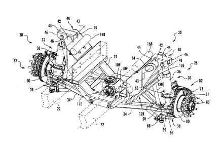
4,653,772.
[0004] It is also known to provide MacPherson type strut IFS assemblies
wherein the
steering knuckle includes an arm portion extending below and transferring the
load to the strut,
as disclose, for example, in US Patent No. 5,192,100.
[0005] It is desirable to reduce loading of both struts and air springs in
an IFS assembly, to
maximize the available wheel cut of an IFS assembly, to simplify vehicle
suspension
installations by OEM manufacturers, provide variable load-carrying and right
height capabilities,
and provide other advancements in areas of IFS technologies and
configurations.
1
CA 02919299 2016-01-28
1 k
SUMMARY
[0006] The present disclosure beneficially provides such advancements.
[0007] According to a first aspect, the present disclosure provides an IFS
assembly including
a single lower control arm having laterally-spaced inboard and outboard ends,
the inboard end
adapted to be pivotally secured to a chassis support structure. A lower air
spring seat is
supported by the lower control arm, the lower air spring seat adapted to
upwardly support the
chassis support structure relative to the lower control arm through an air
spring engaging the
chassis support structure. The IFS assembly includes a strut having upper and
lower ends
disposed along a strut axis, the strut upper and lower ends having relative
movement along and
about the strut axis. The strut upper end is adapted to be pivotally secured
to the chassis support
structure and the strut lower end is coupled to the lower control arm outboard
end. A steering
knuckle is rotatably and axially secured to the strut lower end, the steering
knuckle disposed
below the lower air spring seat and has rotative movement about the strut axis
that is unconfined
by proximity between the steering knuckle and the lower air spring seat and/or
the air spring
through which the lower air spring seat is adapted to support the chassis
support structure.
Consequently, available wheel cut is maximized.
[0008] According to a second aspect, the present disclosure provides an IFS
assembly
including a chassis support structure and a single lower control arm having
laterally-spaced
inboard and outboard ends, the inboard end pivotally secured to the chassis
support structure. A
lower air spring seat is supported by the lower control arm, and an air spring
is supported by the
lower air spring seat and engages the chassis support structure. The chassis
support structure is
upwardly supported by the air spring relative to the lower air spring seat.
The IFS assembly
2
CA 02919299 2016-01-28
' 1
includes a strut having upper and lower ends disposed along a strut axis, the
strut upper and
lower ends having relative movement along and about the strut axis. The strut
upper end is
pivotally secured to the chassis support structure, and the strut lower end is
coupled to the lower
control arm outboard end. A steering knuckle is rotatably and axially secured
to the strut lower
end and is disposed below the lower air spring seat. The steering knuckle has
rotative movement
about the strut axis that is unconfined by proximity between the steering
knuckle and the lower
air spring seat. Consequently, available wheel cut is maximized.
[0009] According to a third aspect, the present disclosure provides
an IFS assembly
including a single lower control arm defining laterally-spaced inboard and
outboard ends, the
inboard end adapted to be pivotally secured to a chassis support structure.
The IFS assembly
includes a strut having upper and lower ends disposed along a strut axis, the
strut upper and
lower ends having relative movement along and about the strut axis. The strut
upper end is
adapted to be pivotally secured to the chassis support structure. The IFS
assembly includes a
steering knuckle including a strut supporting portion affixed to and
supporting the strut lower
end, and a load arm extending below and secured to the lower control arm. The
outboard end of
the lower control arm is disposed between the load arm and the strut lower
end, and the lower
control arm is upwardly supported by the load arm.
[0010] According to a fourth aspect, the present disclosure
provides an IFS assembly
including a chassis support structure and a single lower control arm defining
laterally-spaced
inboard and outboard ends, the inboard end pivotally secured to the chassis
support structure.
The IFS assembly includes a strut having upper and lower ends disposed along a
strut axis, the
strut upper and lower ends having relative movement along and about the strut
axis. The strut
upper end is pivotally secured to the chassis support structure. The IFS
assembly includes a
3
CA 02919299 2016-01-28
steering knuckle including a strut supporting portion affixed to and
supporting the strut lower
end, and a load arm extending below and secured to the lower control arm. The
outboard end of
the lower control arm is disposed between the load arm and the strut lower
end, and the lower
control arm is upwardly supported by the load arm.
[0011] According to a fifth aspect, the present disclosure provides an IFS
assembly including
a single lower control arm defming laterally-spaced inboard and outboard ends,
the inboard end
adapted to be pivotally secured to a chassis support structure, and a steering
knuckle secured to
the lower control arm outboard end. The IFS assembly includes a strut having
upper and lower
ends disposed along a strut axis, the strut upper and lower ends having
relative movement along
and about the strut axis. The strut lower end is fixed relative to the
steering knuckle, and the
strut upper end provided with a clevis ring structure adapted to surround a
bushing extending
therethrough. The strut upper end is adapted to be pivotally secured to the
chassis support
structure through the clevis ring structure and the bushing about a generally
horizontal first axis.
[0012] According to a sixth aspect, the present disclosure provides an IFS
assembly
including a chassis support structure and a single lower control arm defining
laterally-spaced
inboard and outboard ends, the inboard end pivotally secured to the chassis
support structure. A
steering knuckle is secured to the lower control arm outboard end. The IFS
assembly includes a
bushing and a strut having upper and lower ends disposed along a strut axis,
the strut upper and
lower ends having relative movement along and about the strut axis. The strut
lower end is fixed
relative to the steering knuckle, and the strut upper end provided with a
clevis ring structure.
The bushing extends through and is surrounded by the clevis ring structure,
and the strut upper
end is pivotally secured to the chassis support structure through the clevis
ring structure and the
bushing about a generally horizontal first axis.
4
CA 02919299 2016-01-28
100131 According to a seventh aspect, the present disclosure provides an
IFS assembly
including a single lower control arm having laterally-spaced inboard and
outboard ends, the
inboard end adapted to be pivotally secured to a chassis support structure,
and a steering knuckle
secured to the lower control arm outboard end. The IFS assembly includes a
strut having upper
and lower ends disposed along a strut axis, the strut upper and lower ends
having relative
movement along and about the strut axis. The strut lower end is fixed relative
to the steering
knuckle. A torque tube assembly includes an elongate torque tube extending
between first and
second joints at which the torque tube is adapted to be rigidly fixed relative
to the chassis support
structure, and an upper strut mount having laterally-spaced first and second
ends. The first end is
rigidly affixed to the torque tube between the first and second joints. The
strut upper end is
adapted to be pivotally secured to the second end.
100141 According to an eighth aspect, the present disclosure provides an
IFS assembly
including a chassis support structure having a first portion and a torque tube
assembly, and a
single lower control arm having laterally-spaced inboard and outboard ends.
The inboard end is
pivotally secured to the chassis support structure first portion, and a
steering knuckle is secured
to the lower control arm outboard end. The IFS assembly includes a strut
having upper and
lower ends disposed along a strut axis, the strut upper and lower ends having
relative movement
along and about the strut axis. The strut lower end is fixed relative to the
steering knuckle. The
torque tube assembly includes an elongate torque tube extending between first
and second joints
at which the torque tube is rigidly fixed relative to the chassis support
structure first portion, and
an upper strut mount having laterally-spaced first and second ends. The first
end is rigidly
affixed to the torque tube between the first and second joints, and the strut
upper end is pivotally
secured to the second end.
CA 02919299 2016-01-28
[0015] According to a ninth aspect, the present disclosure provides an IFS
module adapted
for installation into a vehicle. The IFS module includes a chassis support
structure having
laterally opposite right and left sides, and adapted for attachment to the
vehicle frame. The IFS
module includes a pair of left and right side single lower control arms, each
lower control arm
defining laterally-spaced inboard and outboard ends, and each inboard end is
pivotally secured to
the chassis support structure. The IFS module includes a pair of left and
right side struts, each
strut having upper and lower ends disposed along a respective strut axis, the
upper and lower
ends of each strut having relative movement along and about the respective
strut axis. The strut
upper ends are pivotally secured to the chassis support structure. The IFS
module also includes a
pair of left and right side steering knuckles, each steering knuckle fixed
relative to the respective
strut lower end and secured to the respective lower control arm outboard end.
BRIEF DESCRIPTION OF THE DRAWINGS
[0016] The various objects, features and attendant advantages of the
present invention will become
fully appreciated as the same becomes better understood when considered in
conjunction with the
accompanying drawings, wherein like reference characters designate the same,
similar or
corresponding parts throughout the several views:
[0017] FIG. 1 is a rear, upper perspective view of an IFS module
incorporating right and left
side IFS assemblies according to an embodiment of the present disclosure;
[0018] FIG. 2 is a top plan view of the IFS module of FIG. 1;
[0019] FIG. 3 is a rear elevation of the IFS module of FIG. 1;
[0020] FIG. 4 is a bottom plan view of the IFS module of FIG. 1;
[0021] FIG. 5 is right side elevation of the IFS module of FIG. 1;
6
CA 02919299 2016-01-28
/
= ,
,
[0022] FIG. 6 is a partially sectioned view of the IFS module of FIG.
5 along line 6-6;
[0023] FIG. 7 is a partially exploded, front, upper perspective view
of the IFS module of
FIG. 1;
[0024] FIG. 8 is a front, upper perspective view of the IFS module of
FIG. 1;
[0025] FIG. 9 is a longitudinal sectional view of a first embodiment
strut used in an IFS
assembly according to the present disclosure; and
[0026] FIG. 10 is a longitudinal sectional view of a second embodiment
strut used in an IFS
assembly according to the present disclosure.
DETAILED DESCRIPTION
[0027] The invention is adaptable to various modifications and
alternative forms, and the
specific embodiments thereof shown by way of example in the drawings are
herein described in
detail. The exemplary embodiments of the present disclosure are chosen and
described so that
others skilled in the art may appreciate and understand the principles and
practices of the present
disclosure. It should be understood, however, that the drawings and detailed
description are not
intended to limit the invention to the particular forms disclosed, but on the
contrary, the intention
is to cover all modifications, equivalents and alternatives falling within the
spirit and scope of the
present invention as defined by the appended claims.
[0028] FIGS. 1-8 depict an embodiment of IFS module 20 which is a free
standing
assemblage adapted for installation into a vehicle. IFS module 20 may be
affixed to vehicle
frame 22 shown in dashed lines in FIG. 1, for example. IFS module 20 includes
chassis support
structure 24 having right side 26 and left side 28 sharing substantially rigid
chassis support
structure first portion 29 to which is attached, or which forms a part of,
right side IFS assembly
7
CA 02919299 2016-01-28
=
30 and left side IFS assembly 32. Alternatively, chassis support structure 24
or first portion 29
thereof may form an integral part of the vehicle to which right and left side
IFS assemblies 30,
32 are installed directly, rather than through an IFS module such as IFS
module 20. Chassis
support structure 24 may be a stamped sheet metal and/or metal beam weldment
formed of
suitably rigid material. Chassis support structure right and left sides 26, 28
as shown are
substantially mirror images of each other. In other words, chassis support
structure 24 is
substantially symmetrical about its lateral center, which coincides with the
lateral center of the
vehicle. Likewise, right and left side IFS assemblies 30, 32 as shown are
substantially mirror
images of each other. Unless indicated otherwise, structural and functional
descriptions herein
which specify neither chassis support structure right or left side 26, 28, nor
right or left side IFS
assembly 30, 32, or components thereof, should be construed to relate to the
chassis support
structure, IFS assembly and components of either side. Moreover, corresponding
elements
between the right and left sides have a common reference numeral and in the
accompanying
Figures, the element of only the right or left side element may be indicated.
100291
In the depicted embodiment, each IFS assembly 30, 32 includes lower control
arm 34,
strut 36 which extends generally vertically along its strut axis 37, steering
knuckle 38, and torque
tube assembly 40. As shown, torque tube assembly 40 is an integrated part of
the respective
chassis support structure right or left side 26, 28, but may be a separate
component affixed
thereto. Torque tube assembly 40 is formed of an elongate torque tube 42 that
extends fore and
aft along generally horizontal axis 43, and laterally extending upper strut
mount 44. Relative to
chassis support structure first portion 29, torque tube 42 is secured at fixed
forward joint 63 and
aft joint 64 spaced along torque tube axis 43. Joints 63, 64 may be welds.
Upper strut mount 44
has inboard end 45 affixed, as by welds, to torque tube 42 at a location
between joints 63, 64,
8
CA 02919299 2016-01-28
and outboard end 46 which extends laterally outward from inboard end 45 in a
generally
horizontal plane.
[0030] Strut upper end 48 and strut lower end 50 are disposed along strut
axis 37, and have
relative movement along and about strut axis 37. Strut upper end 48 is
provided with steel clevis
ring structure 52 that surrounds bushing 54. In the depicted embodiment,
bushing 54 is a
compliance bushing formed of elastomeric material such as vulcanized rubber
surrounding and
bonded to cylindrical steel sleeve 55 and/or the interior surface of clevis
ring structure 52.
Sleeve 55 is concentric with clevis ring structure 52, and compliance bushing
54 may be a
component part of strut 36. Strut upper end 48 is pivotally secured to upper
strut mount outboard
end 46 with bolt 56 and nut 57. Bolt 56 extends along axis 58 through upper
strut mount
outboard end 46 and bushing sleeve 55. In the depicted embodiment, upper strut
mount 44 is
defined by an inverted U-shaped channel having spaced parallel forward flange
60 and aft flange
62 provided at outboard end 46 with apertures aligned along axis 58. Upper
strut mount 44,
strut upper end 48, and elongate bolt 56 thus define a clevis joint. The
interior of bushing sleeve
55 is closely fitted about bolt 56 to resist rotation of strut upper end 48
with strut lower end 50,
though a degree of compliance is obtained through elastic deformation of
compliance bushing
54, generally in a plane perpendicular to strut axis 37. Strut upper end 48
also has a nominal
position relative to chassis support structure 24 in which the axes of bolt
56, bushing sleeve 55
and clevis ring structure 52 are coincident with axis 58, and strut axis 37 is
substantially
perpendicular to axis 58. In the nominal position, elastically deformable
compliance bushing 54
is substantially undeformed. Deviation from the nominal position is the result
of the compliance
facilitated by elastic deformation of bushing 54. Deviation from the nominal
position is typically
caused by angular displacement of clevis ring structure 52 about strut axis 37
due to frictionally
9
CA 02919299 2016-01-28
i
1 ,
,
induced torque imparted on strut upper end 48 by strut lower end 50, at the
onset of or during
rotative movement of steering knuckle 38 about strut axis 37. In some
embodiments, deviation
from the nominal position may also be caused by strut 36 experiencing a
bending moment in fore
or aft directions generally parallel with axis 58.
100311 Strut lower end 50 is fixed at two locations along strut axis
37 to strut supporting
portion 66 of steering knuckle 38. Strut supporting portion 66 includes
encircling clamp 65
which surrounds strut lower end 50 received therethrough, and boss 67 and
mating bracket 68
located below encircling clamp 65. Each of boss 67 and bracket 68 is
configured with a semi-
cylindrical inner surface that engages the outer cylindrical surface of strut
lower end 50. The
semi-cylindrical inner surfaces of boss 67 and bracket 68 are provided with
circumferentially
extending, radially inwardly projecting ridges 70 that are received in
cooperating circumferential
groove 71 (FIGS. 9 and 10) provided in the cylindrical outer surface of strut
lower end 50.
Ridges 70 and groove 71 axially align strut lower end 50 relative to steering
knuckle 38 and
secure them against relative movement along strut axis 37. Frictional
engagement between the
cylindrical outer surface of strut lower end 50 and the interfacing
cylindrical surfaces of
encircling clamp 65, and the clamp defined by boss 67 and bracket 68,
rotatably and axially fix
strut lower end 50 to steering knuckle strut supporting portion 66. Bolts 72
hold bracket 68 and
boss 67 together against strut lower end 50; bolt 72 and nut 73 hold
encircling clamp 65 tightly
closed upon strut lower end 50.
100321 Certain embodiments of IFS module 20 are provided with
components that may be
included in IFS assembly 30, 32 as individually installed in a vehicle, or
which may be installed
subsequent to installation of the IFS assemblies 30, 32. Steering knuckle 38
includes caliper
assembly mounts 74 and spindle 76, to which caliper assembly 78 and rotor 80
of disk brake
CA 02919299 2016-01-28
assembly 82 are respectively attached. Rotor 80 as shown is provided with
central wheel
mounting flange 81 provided with wheel mounting lugs 83 for attachment of the
vehicle wheels
(not shown). A portion of rotor 80 is disposed within caliper assembly 78 in a
manner well-
known to those having ordinary skill in the art, whereby caliper assembly 78
and rotor 80 are
operatively engageable. As discussed herein below, IFS assembly 30, 32
maximizes the
available wheel cut, i.e., the angle in either direction about strut axis 37
that a vehicle front wheel
can be turned.
[0033] As perhaps best seen in FIGS. 4 and 6, steering knuckle 38 is
provided with load arm
84 that extends laterally inwardly and below lower control arm 34, to which
load arm is secured.
Steering knuckle 38 also has elongate turning arm 86 which, in the depicted
embodiment,
extends rearwardly and laterally inwardly from load arm 84 to turning arm
terminal end 88.
Lower control arm 34 has laterally-spaced inboard and outboard ends 90, 92.
Lower control
arm inboard end 90 is pivotally secured to chassis support structure first
portion 29 at a pair of
locations that are spaced fore and aft. These pivotal attachments are about
generally horizontal
and parallel forward and aft axes 94, 96 that extend fore and aft, the
attachments being made
with bolts 98 and nuts 100, as perhaps best seen in FIG. 4.
[0034] Lower control arm outboard end 92 is rotatably secured to, and is
upwardly supported
by, steering knuckle load arm 84 through interconnecting ball joint 102.
Steering knuckle 38
thus places a compressive force onto ball joint 102 and lower control arm 34.
Strut axis 97
extends through ball joint 102. Referring to FIGS. 6 and 7, lower control arm
outboard end 92
has top surface 104 disposed above ball joint 102 and is superposed by strut
axial end 106
defined by strut lower end 50. As noted above, strut lower end 50 is axially
supported by
steering knuckle strut supporting portion 66, and so strut axial end 106 is in
spaced superposition
11
CA 02919299 2016-01-28
with top surface 104. Thus, lower control arm outboard end 92 is sandwiched
between strut 36
and steering knuckle load arm 84 along strut axis 37.
[0035] IFS module 20 includes steering box 108 having housing 109 secured
to chassis
support structure first portion 29 at a laterally central position between
right and left side lower
control arm inboard ends 90. Steering box 108 has rotatable input shaft 110
extending
rearwardly from housing 109, the rearward end of input shaft 110 adapted to be
rotatably
connected to a steering shaft (not shown). Steering box 108 also has rotatable
output shaft 112
downwardly extending through an aperture in chassis support structure first
portion 29 at the
lateral center of chassis support structure 24. Rotatable input and output
shafts 110, 112 are
operably coupled within housing 109 for corresponding rotation. Pitman arm 114
is rotatably
secured to steering box output shaft 112 and converts angular movement of
output shaft 112 to
linear movement of a pair of elongate right and left side tie rods 116 each
individually secured at
one end to pitman arm 114 via an interconnecting tie rod end 118, as perhaps
best seen in FIG. 4.
Each tie rod 116 is secured at its opposite end to a turning arm terminal end
88 via an
interconnecting tie rod end 118. Pitman arm 114, tie rods 116 and tie rod ends
118 thus form
steering linkage between steering box 108 and turning arms 86, through which
coordinated
rotative movements of right and left side steering knuckles 38 about their
respective strut axes 37
is accomplished, these rotative movements induced by rotation steering box
input shaft 110
through steering box output shaft 112 and the steering linkage.
[0036] IFS module 20 and the IFS assemblies 30, 32 include a pair of right
and left side air
springs 120 operably disposed between the respective chassis support structure
right or left side
26, 28 and the respective right or left side lower control arm 34. Each air
spring 120 engages
chassis support structure 24 at a respective right or left side location 122
at which the air spring
12
CA 02919299 2016-01-28
,
,
,
is retained to chassis support structure 24 with threaded fastener 124.
Chassis support structure
24 and air springs 120 are upwardly supported relative to lower control arms
34, and thus by
steering knuckle load arms 84.
[0037] Air spring 120 is supported by lower air spring seat 126, which
is supported by seat
support structure 128 of lower control arm 34. Seat support structure 128 is
located laterally
between lower control arm inboard and outboard ends 90, 92, and projects
upwardly relative
thereto. Seat support structure 128 includes rigid strut member 130 which
extends along
longitudinal axis 132 between lower air spring seat 126 and a location on
lower control arm 34
proximate its outboard end 92, as perhaps best seen in FIGS. 1 and 3. Steering
knuckle 38 is
disposed below lower air spring seat 126 and air spring 120, and rigid strut
member longitudinal
axis 132 diverges from strut axis 37 in an upward direction from lower control
arm 34. Lower
air spring seat 126, air spring 120, and rigid strut member 130 are thus
located well out of the
path of rotative movement of steering knuckle 38 and disk brake assembly 82
carried thereby,
whereby rotative movement of steering knuckle 38 about strut axis 37 is
unconfined by
proximity between steering knuckle 38 and lower air spring seat 126 and/or air
spring 120 is
unconfined by proximity therebetween and available wheel cut is maximized.
Moreover, a
portion of disk brake assembly 82 carried by steering knuckle 38 is receivable
beneath lower air
spring seat 126 during rotative movement of steering knuckle 38 about strut
axis 37.
[0038] FIG. 9 shows the internal structure and further details of strut
36, and FIG. 10 shows
the internal structure and details of alternative embodiment strut 36a, which
may be substituted
for strut 36. Except for distinctions between strut 36 and strut 36a discussed
below and revealed
by a comparison between FIGS. 9 and 10, reference herein and in FIGS. 1-8 to
strut 36 shall be
understood to apply to and encompass strut 36a. Additionally, it is to be
understood that the
13
CA 02919299 2016-01-28
horizontal orientation of struts 36, 36a depicted in FIGS. 9 and 10 is merely
to provide a larger
view than obtainable by depicting them in a substantially vertical
orientation, and does not alter
the context used heretofore with respect to descriptors such as "upper" and
"lower"; "above" and
"below"; "top" and "bottom"; "vertical" and "horizontal"; and the like.
100391 Referring to FIG. 9, strut upper end 48 is defined by cylindrical
strut upper portion
134 and strut lower end 50 is defined by cylindrical strut lower portion 136.
Strut upper and
lower portions 134, 136 are telescopically engaged along strut axis 37, and
respectively form a
strut rod and a strut body. Strut lower portion 136 is sealably closed at its
free end by end cap
138 that defines above-mentioned strut axial end 106. Above-mentioned clevis
ring structure 52
is sealably fixed to the free end of strut upper portion 134. Concentrically
disposed within strut
upper portion 134 is cylindrical damper body 140, within which is slidably
disposed annular
damper valve 142, Damper valve 142 is affixed to one end of elongate damper
rod 144 that
extends therethrough. The opposite end of damper rod 144 is secured to plate
145 sealably fixed
to the interior wall of strut lower portion 136 and relative to end cap 138.
One end of cylindrical
damper body 140 is sealably affixed to strut upper end 48; the opposite end of
damper body 140
is affixed to sliding bearing member 146. The cylindrical space between the
superposing
cylindrical surfaces of strut upper portion 134 and strut lower portion 136
located above sliding
bearing member 146 is vented to atmosphere. Sliding bearing member 146 is
slidably disposed
within cylindrical lower portion 136, and surrounds and moves axially along
valve rod 144.
Sealably surrounding valve rod 144 at the end of damper body 140 affixed to
sliding bearing
member 146, and located below the lower side of damper valve 142 is annular
seal 147. Above
the upper side of damper valve 142 is disk-shaped floating piston 148,
slidably sealed to the
inner diameter of damper body 140. First oil chamber 150 is defined between
damper valve 142
14
CA 02919299 2016-01-28
and floating piston 148, and second oil chamber 152 is defined between damper
valve 142 and
annular seal 147, thereby defining internal monotube damper assembly 153
having controlled oil
flow across damper valve 142 between first and second oil chambers 150, 152
along the path
defined by arrow 154. Damper 153 is thus housed within strut upper and lower
portions 134,
136 and dampens relative motion between strut upper and lower ends 48, 50
along strut axis 37.
100401 Also
housed within strut upper and lower portions 134, 146 is gas spring 156, which
may utilize high pressure nitrogen as the working fluid. Gas spring 156
includes first gas
chamber 158 located in damper body 140 between clevis ring structure 52 and
floating piston
148, and second gas chamber 160 located in strut lower portion 136 and sliding
bearing member
146 annular seal 147 and plate 145. The pressurized nitrogen gas within gas
spring 156 provides
the biasing force that urges strut upper and lower ends 48, 50 apart along
strut axis 37, and thus
allows struts 39 to upwardly support chassis support structure 24 relative to
steering knuckles 38.
Additionally, the high pressure nitrogen gas within gas spring, which acts on
the upper side of
floating piston 148, prevents cavitation in the hydraulic oil of damper 153.
First gas chamber
158 is provided with a circumferentially arranged plurality of orifices 162
through the cylindrical
wall of damper body 140 proximate the axial end thereof. First and second gas
chambers are in
fluid communication along a path indicated by arrow 164, which extends through
orifices 162,
along the outer cylindrical surface of damper body 140, and about damper rod
144 within sliding
bearing member 146. Above the axial end of cylindrical damper body 140, in
clevis ring
structure 52, strut upper end 48 is provided with gas port 166 adapted for
connection with gas
reservoir 168 externally of strut 36. IFS module 20 includes right and left
side gas reservoirs 168
respectively mounted to chassis support structure right and left sides 26, 28.
Each gas spring 156
is adapted to receive gas from and discharge gas to its connected gas
reservoir 168, and is
CA 02919299 2016-01-28
capable of containing gas at selectively variable pressures so as to
compensate for different loads
between the strut upper and lower ends 48, 50 and/or establish different
nominal axial distances
therebetween, thereby enabling changes to vehicle ride height and providing
vehicle kneeling
capabilities.
100411 Referring now to FIG. 10, strut 36a is substantially identical to
strut 36 except for
providing circular wall 170 sealably fixed within cylindrical damper body 140
just below orifices
162, and sealed, third gas chamber 172 within damper body 140 between wall 170
and floating
piston 148. Third gas chamber 172 provides damper 153 with a sealed nitrogen
charge which
bears on the upper side of floating piston 148.
100421 Forces imparted by the pressurized nitrogen in gas spring 156 urge
strut upper and
lower ends 48, 50 apart, and struts 36, 36a therefore upwardly support chassis
support structure
24. Struts 36, 36a act in parallel with air springs 120 to upwardly support
chassis support
structure 24 and other portions of a vehicle's sprung weight relative to
different portions of
steering knuckles 38. Air springs 120 may thus be smaller than prior air
springs operably
disposed in series connection with struts or other springs, and positioned so
as not to constrain
rotative movement of the steering knuckles, maximizing available wheel cut.
100431 While exemplary embodiments have been disclosed hereinabove, the
present
invention is not limited thereto. Instead, this application is intended to
cover any variations,
uses, or adaptations of the present disclosure using its general principles.
16