Note: Descriptions are shown in the official language in which they were submitted.
CA 02919497 2016-01-29
. .
HYBRID LAMINATE
FIELD OF THE INVENTION
[0ool] The present invention relates generally to lamination of sheets and
plates of
dissimilar materials and more particularly to the use of such laminates for
the
manufacture of disc brake pads.
BACKGROUND OF THE INVENTION
[0002] Laminates are generally made from thin laminae of the same or similar
material
stacked together with adhesive between the laminae. They are then pressed and
heated until cured into a one-piece, sheet-like laminate.
[0003] Disc brake pads are generally made by adhering friction material to a
steel
backing plate. This is done using a "batch" process where a measure of powered
friction
material is poured directly onto each backing plate in moulds specific for
each model
and year of vehicle. The moulds are then stacked and compressed under high
heat until
the friction material cures. It follows that brake pad production (and
therefore cost) is
constrained by the number of moulds, the capacity of the presses and the time
for the
friction material to cure or harden. Considering that each car, each model and
each year
can have a different brake pad configuration, the process is expensive and
inefficient.
This requires the use of many moulds and heat presses, and is expensive, but
is the
usual method used to attach friction material to backing plates to form brake
pads.
[0004] It would be very desirable to be able to pre-manufacture cured friction
material
and simply attach it to the backing plate, however, with prior art steel
backing plates this
cannot be done in a way that provides sufficiently strong bond between the
friction
material and the plate.
SUMMARY OF THE INVENTION
[0005] The present invention provides a hybrid laminate disc brake backing
plate
including a base lamina and an interface lamina. The base lamina is a metal
plate
having a surface with piercing members extending from it. Each piercing member
1
CA 02919497 2016-01-29
extends from the surface and initially has a pointed distal end. The interface
lamina is
impaled on the piercing members so that the piercing members extend through
the
interface lamina. Then the distal ends of the piercing members are clinched to
lock the
base lamina and interface lamina together. The interface lamina is made from a
material
that is pierceable by the piercing members and which is adhesively bondable to
cured
friction material.
[0006] The base lamina is preferably made of steel.
[0007] The material of the interface lamina and the adhesive are preferably
selected so
that the adhesive bonds cured friction material to the hybrid laminate disc
brake backing
plate sufficiently strongly for normal use in a vehicle disc brake system.
[0008] The surface of the base lamina may have multiple patches of piercing
members
extending from it, in which case the interface lamina then has multiple
separate
portions, each portion corresponding to one of the patches of piercing
members. In such
embodiments, each portion of the interface lamina is impaled on one of the
patches of
piercing members. The patches of piercing members may be spaced apart to
permit air
flow between friction pucks attached to the interface lamina.
[0009] The invention also provides a disc brake pad formed from the hybrid
laminate
disc brake backing plate described above and at least one puck of friction
material.
Each puck of friction material is adhesively bonded to the interface lamina.
The friction
pucks may be bonded to the interface lamina by a thermoplastic or thermoset
resin.
[0010] The interface lamina may be made of abrasive filled resin-reinforced
fibre.
[0011] The interface lamina may be a coated abrasive comprising a sheet with a
layer of
adhesively-bound grains dispersed on it. The grains may be sand, aluminum
oxide,
silicon carbide, garnet, or emery.
[0012] The invention also provides a hybrid laminate for adhering to an
attachment,
where the laminate has a base lamina and an interface lamina. The base lamina
is a
surface with piercing members extending from it. Each piercing member extends
from
2
CA 02919497 2016-01-29
the surface and initially has a pointed distal end. The interface lamina is
impaled on the
piercing members so that the piercing members extend through the interface
lamina,
and the distal ends of the piercing members are clinched to lock the base
lamina and
interface lamina together. The interface lamina is made from a material that
is selected
to be pierceable by the piercing members and which is adhesively bondable to
the
attachment. The base lamina is preferably made of steel. A functional material
different
from the materials used to form the base lamina and the interface lamina may
be
disposed between the base lamina and the interface lamina. The functional
material
may be a sealant.
[0013] The invention also provides a hybrid laminate disc brake backing plate
having a
base lamina and an interface lamina, where the base lamina is a metal plate
having a
surface with piercing members having clinched heads extending from it. The
piercing
members pass through the interface lamina, and the clinched heads lock the
base
lamina and interface lamina together. The interface lamina is made from a
material that
is adhesively bondable to cured friction material.
[0014] The invention also provides a method of making a hybrid laminate for
adhering to
an attachment. The method employs a base lamina having a surface with piercing
members extending from it, each piercing member extending from the surface and
having a pointed distal end. It also employs an interface lamina made from a
material
that is selected to be pierceable by the piercing members and that is
adhesively
bondable to the attachment. The method involves first positioning the
interface lamina
above the piercing members and then impaling the interface lamina onto the
piercing
members by using a pressure pad to press the interface lamina down onto the
piercing
members so that the distal ends of the piercing members extend through the
interface
lamina and into the pressure pad. Then the pressure pad is removed and the
distal
ends of the piercing members are clinched to clamp and secure the base lamina
and
interface lamina together. The clinching of the distal ends of the piercing
members may
be done by pressing a hard plate down on the distal ends of the piercing
members. The
clinching of the distal ends of the piercing members may be done by rolling a
roller over
3
CA 02919497 2016-01-29
the distal ends of the piercing members extending through the interface
lamina. The
pressure pad may be made from an elastomer. The attachment may be a puck of
brake
friction material, and the base lamina may be made of steel, and the hybrid
laminate
configured to be a disc brake backing plate. The method may further include a
step of
adhering one or more pucks of friction material to the interface lamina to
produce a
braking pad.
[0015] The invention also provides another method of making a hybrid laminate
for
adhering to an attachment. The method employs a base lamina having a surface
with
piercing members extending from it, each piercing member extending from the
surface
and having a pointed distal end. It also employs an interface lamina made from
a
material that is selected to be pierceable by the piercing members and that is
adhesively bondable to the attachment. The method involves first positioning
the
interface lamina above the piercing members and impaling the interface lamina
onto the
piercing members by using a hard pressure pad to press the interface lamina
down onto
the piercing members so that the distal ends of the piercing members extend
through
the interface lamina and are then clinched by the pressure pad as the
interface lamina
is pressed against the surface of the base lamina. The clinching of the distal
ends of the
piercing members locks the interface lamina to the base lamina.
BRIEF DESCRIPTION OF THE DRAWINGS
[0016] Figure 1 is a side cross-sectional view of a laminate, showing a barbed
base
lamina below an interface lamina that has been impaled thereon by a penetrable
pressure pad above and having an optional non-lamina material between the
laminae
with functional properties, such as sealing.
[0017] Figure 2 is a side cross-sectional view of the laminate of Figure 1,
where the
exposed barb tips have been headed (clinched or bent) over onto the interface
surface
of the interface lamina by the use of the hard (barb-impenetrable) pad above.
4
CA 02919497 2016-06-15
[0018] Figure 3 is a side cross-sectional view of the laminate of Figure 1,
with the
addition of a purposeful lamina (an "attachment") that has been adhesively
bonded to
the interface surface of the interface lamina.
[0019] Figure 4 is a perspective fragmentary view of a hybrid laminate
according to the
instant invention showing a base lamina and an interface lamina. A purposeful
outer
layer or lamina is bonded thereto. The original barbs are shown with pointed,
piercing
tips onto which the interface lamina has been impaled, and a hard plate has
headed the
protruding tips down onto the interface surface.
[0020] Figure 5 is a perspective view of a disc brake pad made using the
instant
invention where the brake friction material comprises two cylindrical pucks
(one in
dotted outline) that are adhesively bonded to a single piece of an interface
lamina.
[0021] Figure 6 is a perspective view of the disc brake pad of Figure 5, where
the
interface layer is in two pieces located over two areas ("patches") from which
the barbs
extend.
[0022] Figure 7 shows a side view of a brake pad employing a preferred
embodiment of
a hybrid laminate.
DETAILED DESCRIPTION
[0023] In the instant invention a hybrid laminate is made from two laminae
made from
different materials that are joined mechanically.
[0024] The hybrid laminate preferably has two laminae or layers: a thicker
base lamina
having pointed piercing members ("barbs") rising from the surface; and at
least one
thinner interface lamina impaled or applied onto the barbs such that the tips
of the barbs
protrude above the interface lamina. As used herein, "barb" and "piercing
member"
describe any type of nail-like or pin-like structure, or hooked structure,
raised from the
surface of a material by carving, gouging, planing or scraping its surface,
such as is
described in Canadian patent numbers 1,330,521, 1,337,622, and 2,127,339 and
in
Canadian patent application number 2,778,445. The use of such textured
materials to
CA 02919497 2016-06-15
form laminates is described in Canadian patent application numbers 2,778,455,
2,821,897 and 2,855,378.
[0025] The barbs may extend across the entire surface of the base lamina or be
located
in two (or more) separate localized patches. The interface lamina can be one
piece or
may comprise multiple shaped pieces to match the locations and areas
corresponding
to patches of barbs, if the barbs are in patches, each piece being sized and
shaped (as
are the patches of barbs) to be adhered to a particular attachment (such as a
puck of
friction material of a particular size and shape).
[0026] The two laminae may be assembled using a barb-penetrable pressure pad
made
of a suitable material such as an elastomer, wood, soft plastic or the like,
to press the
interface lamina down onto the barbs. A suitable pressure pad will allow the
barbs' tips
to penetrate the pressure pad as the interface lamina descends against the
base lamina
and the barb tips pierce through the upper surface of the interface lamina. By
exerting
sufficient pressure, the bottom of the interface lamina is pushed down against
the
substantially flat surface of the base lamina from which the barbs extend, and
the
pointed tips ("distal ends") of the barbs extend through the interface
laminate, out of
(protruding from) the upper surface of the interface laminate, and into the
pressure pad.
[0027] It is preferred that each barb extends substantially perpendicularly
from the
substantially flat surface of the base lamina to facilitate the impaling of
interface lamina
on the base lamina. However, in some cases, some or all of the barbs may not
be
perpendicular to the surface.
[0028] The barb tips are then headed (bent over or clinched) by means of a
hard plate
or roller to effectively clamp and secure the two laminae together. There may
be
included an adhesive, sealer, coating, plating, inhibitor, or the like between
laminae.
[0029] Of course, in some combinations of lamina properties, the pressure pad
for
pressing could be a barb-impenetrable pad such as the same hard pad used for
6
CA 02919497 2016-01-29
heading, so that the interface lamina is pressed down onto the barbs, and all
the tips
are headed (or "clinched") in one pressing operation.
[0030] A wide range of materials may be selected for the two laminae based on
relative
hardness of the laminae and on the final use. For example, barbs on an
aluminum or
copper base lamina are softer than those of steel and so may not be able to
penetrate
an interface lamina that is too hard.
[0031] In this way, the instant hybrid laminate may be configured to provide a
select
interface surface that is very well suited for the attachment of other
laminae, objects,
sheets or plates formed from a wide range of materials. In this way, the
instant hybrid
laminate overcomes certain limitations in joining dissimilar materials
together found in
the prior art. For example, thermal expansion differences can be mitigated by
choosing
a material for the interface lamina with intermediate thermal properties
(intermediate
between the thermal properties of the base lamina and the attachment to be
adhered to
the laminate).
[0032] Likewise the interface lamina can be chosen to have ideal adhesive
properties,
such as being fibrous or porous and the like, so that objects or outer layers
("attachments") can be securely bonded to the interface lamina, even when the
base
lamina is, for example, hard steel that would not adhesively bond well to the
attachment.
In a disc brake back plate application, the interface lamina material is
selected to be a
material that is pierceable by the piercing members and which is well suited
for
adhesive bonding to friction material used in disc brake systems. Such
materials are
well known to skilled persons. Herein, the phrase X being "adhesively
bondable" to Y in
a particular article means that X and Y may be securely bonded by known
adhesives
normally used in such or similar articles, such that the bond is sufficiently
strong that the
article will perform in a commercially acceptable manner. For example, in a
disc brake
bad, the bond of a puck of friction material is "adhesively bondable" to an
interface
lamina if the bond is sufficiently strong for use in a vehicle disc brake
system. In such
use, the puck is subject, during normal use, to enormous shear forces, so, for
example,
a puck of friction material is clearly not adhesively bondable directly to a
metal (e.g.
7
CA 02919497 2016-01-29
steel) backing plate. This fact is a key motivation for the instant invention.
Pucks of
friction material are adhesively bondable to a range of materials that may be
used to
form interface laminae, and such materials (and adhesives) are known to
skilled
persons.
[0033] In the case of a disc brake pad, the instant hybrid lamination offers
multiple
benefits. Using a typical steel backing plate as the base lamina, an interface
lamina can
be chosen having ideal adhesive bonding properties. Then, the wearable brake
friction
material "puck" that has been pre-formed can be bonded thereto.
[0034] Uncommon friction puck shapes such as a circular, rectangular,
trapezoidal or
polygonal shapes become possible (referring to the horizontal cross-sectional
shape, so
that, for example, a "circular" puck is a disc, e.g. like item C in Figures 5
and 6). The
upper and lower surfaces of a puck are generally flat, the upper face being
designed to
contact and apply frictional force to one side of a disc brake rotor, and the
lower face
being designed to be adhered to the upper surface of the interface lamina,
which is
generally flat. These can be arranged in numerous ways with space between
pucks.
This, in turn, as is well known, makes for superior cooling of the friction
pad resulting in
safer brake pads that are longer lasting and less subject to brake fade.
[0035] Furthermore, the arrangement of the present laminate allows for lower
cost of
production since friction pucks can be "cookie cut" to a few standard
diameters, cured
off-site, and then delivered ready for assembly with a hybrid laminate backing
plate. In
this way a "continuous" brake manufacturing process can be used with distinct
speed
and cost advantages over the prior art "batch" manufacturing process.
(0036] Barbs can be added to ductile materials by using a press with tooling
that has a
set of blades each with multiple teeth. The blades are made to travel
oppositely across
a material's surface to plough (plow), broach or plane, short shallow grooves
("stop
grooves") that are non-piercing. The material from the grooves is displaced
upwards in
the form of sharp, pointed piercing members or "barbs", which are firmly
attached to the
8
CA 02919497 2016-01-29
"stop" end of each groove. The barbs can extend over an entire surface or in
patches in
different locations spaced apart on the surface.
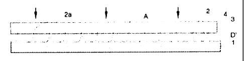
[0037] In Figure 1 the base lamina 1 (or just "base") has barbs 2 with barb
tips 2a that
have passed through the surface 4 of a thin, interface lamina 3 and into a
pressure pad
A (which may be made, e.g., from rubber, urethane, wood or soft plastic). The
choice of
pressure pad material depends on the hardness of the interface lamina 3, the
force
needed to impale the interface lamina 3 on the barbs 2, and the strength of
the barb tips
2a.
[0038] In Figure 2, a hard (barb-impenetrable) heading plate B is forced down
against
the exposed barb tips 2a to create rivet- or nail-like heads 2b at the end of
each barb 2
that forcibly clamp (or lock) the two laminae together.
[0039] The material for the interface lamina 3 may be chosen from any thin,
pierceable
sheet, foil, membrane, paper, board, resin bonded fibre/particle sheet, or the
like, whose
specification provides a body and a surface suitable for its operational
environment.
Heat, adhesiveness, pressure, shear, wear, friction, chemical resistance and
cost may
all be factored into the choice.
[0040] Generally the interface surface 4, being the upper surface of the
interface lamina
3, is functionally very important, especially if adhesive bonding is used to
secure an
outer object or layer C (an "attachment") to the hybrid laminate. For example,
the
interface lamina 3 may be a sheet of abrasive coated paper or abrasive filled
resin-
reinforced fibre, in which case the interface body offers heat resistant,
compressive
strength, low cost, and, an interface surface having excellent bonding
properties.
[0041] As depicted in Figure 1, a sealant, coating or adhesive layer D'
(interrupted
dotted line) may be employed between the two laminae. While this is not
required to
make the instant hybrid laminate, such intermediate layers may provide
benefits such
as improved strength, sealing, rust prevention and the like.
9
CA 02919497 2016-01-29
[0042] Figure 4 shows a perspective view of a laminate product 10 made
according to
the instant invention. The forward portion has been cut away to show the
underlying
construction. The exposed barbs 2 on the left rise up from the base lamina 1
and have
pointed, piercing tips 2a, some of which are shown as having pierced through
the
interface lamina 3. Headed tips 2b are shown in dotted outline beneath the
adhesive
layer D. These riveted or clinched heads 2b bear down onto interface surface 4
of the
interface lamina 3 so as to clamp/secure the two laminae together. Attachment
C above
is bonded onto the interface surface 4 of the interface lamina 3 by the
adhesive layer D.
Adhesives may include thermoplastic and thermoset resins.
[0043] Figure 5 shows a disc brake pad 20 made according to the instant
invention. Two
disc-shaped friction pucks C (right) and C' (left, in dashed outline) are
shown attached
to the interface lamina 3. The friction pucks are pre-manufactured; that is,
they are
moulded/shaped and cured so they are ready to be adhesively bonded to the
hybrid
laminate backing plate 30, which comprises a shaped steel base lamina 1' and a
shaped interface lamina 3' whose interface surface 4 receives the adhesive D
(shown
having oozed out from beneath the friction pad C).
[0044] Figure 6 shows the same brake pad 20 as shown in Figure 5, but with the
interface lamina 3' in two pieces to match two spaced patches of barbs 2 on
the base
lamina 1'. Any number of such barbed patches and matching interface lamina
portions
may be used in accordance with brake pad design requirements. For example, a
large
backing plate may have barbs arranged in two or more circular patches with
space
between each patch. In such a case it may be preferable to have a separate
interface
lamina 3' for each patch of barbs, each configured to receive and attach to
one friction
puck C.
[0045] When designed to be used with two piston calipers (not shown), the
friction
pucks C, C' may be advantageously positioned directly on axis with the pistons
so as to
offer maximum resistance to flex and force distribution. More than two smaller
friction
pucks or one single friction puck are also contemplated.
CA 02919497 2016-01-29
[0046] It can be readily appreciated by those skilled in the art that there
will be
considerable air flow all around the friction pucks cooling them more quickly
for safer
braking.
[0047] Figure 7 shows a brake pad employing a preferred embodiment of a hybrid
laminate that is particularly well suited for use to make a disc brake pad.
The interface
lamina 3 is a sheet 30' with a layer of adhesively-bound grains 3' evenly
dispersed
thereon to form what is commonly referred to as a coated abrasive. The
construction
therefore resembles ordinary waterproof sandpaper such as that used for wet
sanding
auto body paint. Such an interface lamina can be said to have an internal
reinforcement,
or be a "virtual solid" in that it comprises high-strength, tightly packed
solid grains
embedded in a tough, waterproof adhesive and distributed to a precise
thickness on a
tough sheet material such as impregnated papers, resin reinforced fibres and
cloths,
vulcanized fiber, plastic films, phenolic sheet and the like on a tough sheet
backing
material.
[0048] Grains are accurately sorted by size. They can be sand, aluminum oxide,
silicon
carbide, garnet, emery and the like. Sand is likely the best (cheap, strong)
for the brake
application.
[0049] The backing has adhesive applied onto which the gains are laid by
gravity or
electrostatic means and a sizing/coating applied. Then the sheet is baked dry
and rolled
for shipment.
[0050] Waterproof adhesives include water based phenolic and urea resins.
[0051] Examples of pierceable material include: paper, fibreglass, mica,
cloth, coated
abrasives, vulcanized fiber, plastic films, and combinations thereof.
[0052] The result is an easily pierceable interface layer 3 with remarkable
properties.
These include: high compression strength, heat resistance, low thermal
conductivity,
and low cost. In addition, because the grains are packed tightly they bear
against each
other and against the barbs that have penetrated therethrough. The result is
an
11
CA 02919497 2016-01-29
interface layer offering enormous shear strength (important for safe braking)
because
the high shear loads that develop on the friction puck C (from the brake
rotor) are
effectively transmitted to the base lamina 1 via multiple paths through packed
grains 3'
to barbs 2 and into base lamina I. In this way there is no weak shear plane
through the
interface lamina 3 as would be the case with a homogeneous interface lamina
material
without the internal reinforcement provided by the packed grains.
[0053] The forgoing disclosure as it relates to brake pads can facilitate a
continuous
brake pad manufacturing process that offers significant advantages of cost and
speed
of production compared to the currently used "batch" process.
[0054] With the instant invention, pucks in a standard set of sizes (e.g.,
small, medium
and large) and shapes can be optimally positioned on any size backing plate -
fewer
pucks on smaller plates for lighter vehicles and more on larger plates for
faster and/or
heavier vehicles. Thus the need for, e.g., hundreds of moulds and heated
presses is
eliminated. Modern adhesives cure at room temperature and no continuous
pressing is
required.
[0055] In addition, the instant hybrid backing plate offers the opportunity to
mix the
friction formulations of the pucks or to add a thin tell-tale pad whose
ablated powder can
be detected about the wheels of the vehicle thereby indicating when brakes
need
replacing.
[0056] While the foregoing description has focused on the use of the new
hybrid
laminate for making hybrid laminate disc brake backing plates to which can be
adhered
pre-made cured pucks of friction material to form disc brake pads, the use of
the hybrid
laminate is not limited to brake backing plates. A hybrid laminate made
according to the
invention may be advantageously employed in any situation where one wishes to
adhesively adhere material to a metal, such as steel (or other ductile
material), lamina
where the material (an "attachment") does not adhere well to metal by directly
attaching
it to the metal lamina using adhesive. Instead the material can be adhered to
an
interface lamina locked to the steel lamina by clinched barbs, as described
above,
12
CA 02919497 2016-01-29
where the interface lamina material is selected to be a material that is
pierceable by the
piercing members and which is well suited for adhesive bonding to the material
of the
attachment.
[0057] It should be understood that the above-described embodiments of the
present
invention, particularly, any "preferred" embodiments, are only examples of
implementations, merely set forth for a clear understanding of the principles
of the
invention. Many variations and modifications may be made to the above-
described
embodiment(s) of the invention as will be evident to those skilled in the art.
That is,
persons skilled in the art will appreciate and understand that such
modifications and
variations are, or will be, possible to utilize and carry out the teachings of
the invention
described herein.
[0058] Where, in this document, a list of one or more items is prefaced by the
expression "such as" or "including", is followed by the abbreviation "etc.",
or is prefaced
or followed by the expression "for example", or "e.g.", this is done to
expressly convey
and emphasize that the list is not exhaustive, irrespective of the length of
the list. The
absence of such an expression, or another similar expression, is in no way
intended to
imply that a list is exhaustive. Unless otherwise expressly stated or clearly
implied, such
lists shall be read to include all comparable or equivalent variations of the
listed item(s),
and alternatives to the item(s), in the list that a skilled person would
understand would
be suitable for the purpose that the one or more items are listed.
[0059] The words "comprises" and "comprising", when used in this specification
and the
claims, are to used to specify the presence of stated features, elements,
integers, steps
or components, and do not preclude, nor imply the necessity for, the presence
or
addition of one or more other features, elements, integers, steps, components
or groups
thereof.
[0060] The scope of the claims that follow is not limited by the embodiments
set forth in
the description. The claims should be given the broadest purposive
construction
consistent with the description and figures as a whole.
13