Note: Descriptions are shown in the official language in which they were submitted.
CA 02919732 2016-02-03
Description
DIRECT-INSERTION BALUSTER CONNECTING DEVICE
Field of the Invention
The present invention relates to a baluster connecting device, and
particularly relates
to a direct-insertion baluster connecting device, belonging to the field of
fences.
Background of the Invention
In existing fence systems, common baluster installing methods are relatively
complex
and cumbersome, some requiring to weld on site a baluster to an upper rail and
a
lower rail, however needing appearance treatment after welding, and some
involving
fabricating a plurality of balusters into a whole, and then splicing the same
on site, but
the whole rail structure is large in volume and unadjustable in the splicing
size. These
bring great trouble to on-site installation and need great human and material
resources.
Summary of the Invention
In order to solve the above-mentioned technical problems, the present
invention sets
forth a direct-insertion baluster connecting device which is convenient for
disassembly and assembly, safe and beautiful.
To achieve the above object, the present invention adopts a technical solution
as
follows: a direct-insertion baluster connecting device includes a fence frame
and a
plurality of balusters uniformly arranged within the fence frame; the fence
frame is a
square frame jointly consisting of two vertical posts, an upper rail and a
lower rail; the
fence frame and the balusters are all hollow tubes; and a plurality of
connectors are
arranged about the lower end of each vertical post.
Preferably, a plurality of preformed holes for installing the balusters are
provided
uniformly and symmetrically in the upper rail and the lower rail respectively.
Preferably, an upper plastic sleeve and a lower plastic sleeve are embedded at
the two
ends of each baluster respectively, the upper plastic sleeve being installed
in the
CA 02919732 2016-02-03
Description
preformed hole of the upper rail, the lower plastic sleeve being installed in
the
preformed hole of the lower rail, and the length of the upper plastic sleeve
being
larger than that of the lower plastic sleeve.
Preferably, the two ends of the lower rail are installed between the lower
ends of the
two vertical posts respectively by connectors.
Preferably, the connector, as a rectangular frame, is provided with a boss in
a middle
position therein, and provided with opening support bars at both sides of the
lower
part thereof respectively; the lower rail is a hollow rectangular tube, and
the two ends
of the lower rail are inserted into inner frames of the connectors, and
sleeved on the
bosses; the width between edges of the two opening support bars is larger than
that of
the lower rail; to install the lower rail, the lower rail is directly inserted
into the inner
frames of the connectors and sleeved on the bosses, thus achieving preliminary
positioning of the lower rail to prevent deviation of the installed lower
rail.
Preferably, shims are provided at both ends of the lower rail respectively,
and the
shims are U-shaped pieces, sleeved on the lower part of the lower rail; the
width of
the shims is larger than that between the edges of the two opening support
bars; after
positioned, the lower rail is lifted up, and the shims slide into the inner
frames of the
connectors and rest on the opening support bars, thus well positioning the
lower rail in
the connectors, the opening support bars playing a supporting role, and the
lower rail
being propped up by the U-shaped pieces and placed within the connectors,
which is
very convenient.
Preferably, the upper rail is a composite section, which is possibly flexible
extrusion
layer + aluminum substrate, or decorative thin metal layer + aluminum
substrate, for
the purpose of bringing in more comfort of grasping after the upper rail is
externally
provided with a clad layer of various materials, and the clad layer on the
vertical posts
may also be subjected to various decorative surface treatment so that the
upper rail
appears more elegant and beautiful.
Preferably, the connector is also provided with a plurality of screw holes,
and the
assembled lower rail is fixed by anti-detachment screws. The lower rail being
fixed by
the anti-detachment screws after positioned and assembled prevents stealthy
2
CA 02919732 2016-02-03
Description
disassembly of the fence, being very safe. Moreover, the lower rail is
directly inserted
into the connectors with no need to weld or expose the lower rail, thus
appearing very
beautiful.
Preferably, the vertical posts are hollow rectangular tubes, and connectors
are
arranged on four faces of the lower ends of the vertical posts respectively.
The
connectors are arranged in different directions of the vertical posts.
Connectors of one
or more directions can be installed according to requirement of connection of
the
vertical posts. Of course, the vertical posts may also be cylindrical tubes.
The present invention has the beneficial effect that the direct-insertion
baluster
connecting device adopted in the present invention can be used for the
installed fence
frame formed by the vertical posts, upper rail and lower rail, and then it
only needs to
directly insert the balusters and make connection in a specified manner. The
whole
connecting process is a welding-free process, and only needs manual assembly
in a
DIY manner, thus ensuring beauty and safety, as well as convenient and labor-
saving
assembly, and it can be accomplished without too much auxiliary work.
Brief Description of the Drawings
Fig. 1 is a structure diagram of the present invention;
Fig. 2 is a structure diagram of a fence frame of the present invention;
Fig. 3 is an installation diagram of a lower rail;
Fig. 4 is a partial structure diagram of a baluster;
Fig. 5 is a partial enlarged view of A in Fig. 4.
Fig. 6 is a partial enlarged view of B in Fig. 4.
Fig. 7 is a structure diagram before a shim is inserted into a connector inner
frame;
Fig. 8 is a structure diagram after a shim is inserted into a connector inner
frame;
Fig. 9 is a structure diagram of a shim;
Fig. 10 is a structure diagram of a connector;
Fig. 11 is an installation diagram of a baluster and upper and lower plastic
sleeves;
Fig. 12 is a partial structure diagram of an upper rail;
Reference numerals: 1. vertical post, 2. upper rail, 3. connector, 4. shim, 5.
lower rail,
3
CA 02919732 2016-02-03
Description
6. baluster, 7. upper plastic sleeve, 8. lower plastic sleeve, 9. connector,
rivet nut, 10.
preformed hole, 11. screw hole, 2A. boss, 2B. opening support bar.
Detailed Description of the Embodiments
The present invention is further described below in detail in conjunction with
specific
implementations.
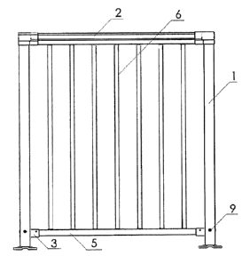
As shown in Figs. 1-12, a direct-insertion baluster connecting device includes
a fence
frame and a plurality of balusters 6 uniformly arranged within the fence
frame; the
fence frame is a square frame jointly consisting of two vertical posts 1, an
upper rail 2
and a lower rail 5; the fence frame and the balusters 6 are all hollow tubes;
and a
plurality of connectors 9 are arranged about the lower end of each vertical
post 1.
A plurality of preformed holes 10 for installing the balusters 6 are provided
uniformly
and symmetrically in the upper rail 2 and the lower rail 5 respectively.
An upper plastic sleeve 7 and a lower plastic sleeve 8 are embedded at the two
ends of
each baluster 6 respectively, the upper plastic sleeve 7 being installed in
the
preformed hole 10 of the upper rail 2, the lower plastic sleeve 8 being
installed in the
preformed hole 10 of the lower rail 5, and the length of the upper plastic
sleeve 7
being larger than that of the lower plastic sleeve 8.
The two ends of the lower rail 5 are installed between the lower ends of the
two
vertical posts 1 respectively by connectors 3.
The connector 3, as a rectangular frame, is provided with a boss 2A in a
middle
position therein, and provided with opening support bars 2B at both sides of
the lower
part thereof respectively; the lower rail 5 is a hollow rectangular tube, and
the two
ends of the lower rail 5 are inserted into inner frames of the connectors 3,
and sleeved
on the bosses 2A; the width between edges of the two opening support bars 2B
is
larger than that of the lower rail; to install the lower rail 5, the lower
rail 5 is directly
inserted into the inner frames of the connectors 3 and sleeved on the bosses
2A, thus
achieving preliminary positioning of the lower rail 5 to prevent deviation of
the
installed lower rail 5.
Shims 4 are provided at both ends of the lower rail 5 respectively, and the
shims 4 are
4
CA 02919732 2016-02-03
Description
U-shaped pieces, sleeved on the lower part of the lower rail 5; the width of
the shims
4 is larger than that between the edges of the two opening support bars 2B;
after
positioned, the lower rail 5 is lifted up, and the shims 4 slide into the
inner frames of
the connectors 3 and rest on the opening support bars 2B, thus well
positioning the
lower rail 5 in the connectors 3, the opening support bars 2B playing a
supporting
role, and the lower rail 5 being propped up by the U-shaped pieces and placed
within
the connectors 3, which is very convenient.
The upper rail 2 is a composite section, which is possibly flexible extrusion
layer +
aluminum substrate, or decorative thin metal layer + aluminum substrate, for
the
purpose of bringing in more comfort of grasping after the upper rail is
externally
provided with a clad layer of various materials, and the clad layer on the
vertical posts
may also be subjected to various decorative surface treatment so that the
upper rail
appears more elegant and beautiful.
The connector 3 is further provided with two screw holes 11, and the assembled
lower
rail 5 is fixed by anti-detachment screws. The lower rail 5 being fixed by the
anti-detachment screws after positioned and assembled prevents stealthy
disassembly
of the fence, being very safe. Moreover, the lower rail 5 is directly inserted
into the
connectors 3 with no need to weld or expose the lower rail 5, thus appearing
very
beautiful.
The vertical posts I are hollow rectangular tubes, and connectors 9 are
arranged on
four faces of the lower ends of the vertical posts I respectively. The
connectors 9 are
arranged in different directions of the vertical posts I. Connectors 3 of one
or more
directions can be installed according to requirement of connection of the
vertical posts
1. Of course, the vertical posts 1 may also be cylindrical tubes.
The assembly process is as follows:
(1) the vertical posts 1, the upper rail 2 and the lower rail 5 are assembled
according
to tube interfaces to form a square frame, and the balusters 6 are inserted
into the
preformed holes 10 of the upper rail 2 and the lower rail 5;
(2) to install the lower rail 5, first the connectors 3 are installed at the
lower ends of
the two vertical posts 1, and then the two ends of the lower rail 5 are
inserted into the
CA 02919732 2016-02-03
Description
connectors 3;
(3) in inserting the lower rail 5 into the inner frames of the connectors 3,
the lower rail
is sleeved on the bosses 2A, thus achieving preliminary positioning;
(4) after the lower rail 5 is positioned, the lower rail 5 is lifted up, the
shims 4 are
sleeved at the lower parts of the two ends of the lower rail 5, the shims 4
slide into the
inner frames of the connectors 3 and rest on the opening support bars 2B, thus
accomplishing assembly of the whole lower rail 5; and
(5) after assembly and positioning of the lower rail 5, the lower rail 5 is
fixed by
anti-detachment screws, thus accomplishing assembly of the whole rail fence.
6