Note: Descriptions are shown in the official language in which they were submitted.
1
Friction ring body for a rail wheel brake and rail wheel brake
Description
The present invention relates to a rail wheel brake for arrangement on the
wheel web of a rail wheel for a rail vehicle for forming a rail wheel brake
and also re-
lates to such a rail wheel brake.
Prior art
EP 1 460 283 Al for example shows friction ring bodies in arrangement on
the wheel web of a rail wheel for a rail vehicle for forming a rail wheel
brake. The fric-
tion ring bodies are made of cast steel and have moldings with which the
friction ring
bodies rest against the surface of the wheel web. The moldings also serve for
receiv-
ing through-bolts to screw the friction ring bodies against each other by
passing the
through-bolts through the holes in the wheel web. The shown geometry of the
friction
ring bodies can be produced in a practical technical way only with a
relatively complex
molding method.
Further friction ring bodies for arrangement on the wheel web of a rail
wheel are shown in EP 1 298 333 B1 and in DE 44 17 813 Al. The production of
such
friction ring bodies by casting requires technically complicated molds,
especially if the
friction ring bodies have moldings with which they rest against the wheel web
of the
rail wheel and if the friction ring bodies for example must have cooling fins
to cool the
friction rings.
Summary of the invention: Object, Solution Advantages
Therefore the object of the invention is a further development of easily pro-
ducible friction ring bodies for arrangement on the wheel web of a rail wheel
for
forming a rail wheel brake. In particular, the friction ring bodies should be
able to be
easily fitted with attachment bodies, wherein the attachment bodies should in
partic-
ular form cooling bodies and / or connection bodies by which the friction
rings can be
connected to the wheel web.
The invention includes the technical teaching that the friction ring body has
a friction ring cut out of a flat metal material and several attachment bodies
arranged
at the friction ring by means of an integrally bonding connection process.
CA 2920060 2017-10-05
CA 02920060 2016-02-01
2
The invention therefore proposes friction ring bodies which can be manufac-
tured in a two-dimensional manufacturing process, so that the provision of a
flat met-
al material, such as a flat steel material or a flat aluminum material is
already suffi-
cient to cut the friction ring body two-dimensionally out of the flat metal
material
with the required contour. The cutting processes for cutting out the friction
ring bod-
ies from a flat metal material which can be provided for example by the meter
or as a
continuous product may concern known methods such as a laser beam cutting,
water
jet cutting, a thermal cutting or a shear cutting method. In this way the
friction ring
bodies can be provided according to the invention in the simplest way without
the use
of a casting method, wherein the friction ring bodies and the cut surfaces, or
at least
the outer contour and the inner contour can optionally be finished
mechanically. Here
it is a major advantage that the attachment bodies can be available as
individual
parts, and the attachment bodies are arranged at the friction ring by means of
an in-
tegrally bonding connection process.
The attachment bodies can be designed in various ways and can perform dif-
ferent functions. For example, the attachment bodies can form cooling
elements, by
which a cooling air flow can be formed between the friction ring and the wheel
web
when the friction ring body is arranged at the wheel web. Further, the
attachment
bodies may form connection bodies, by which the friction ring is connected to
the
wheel web. In this way the connection bodies can have a cooling function, as
well.
Thus, attachment bodies may be provided which are arranged as a cooling
element
only at the surface of the friction ring and have a distance to the surface of
the wheel
web. The connection bodies on the other hand extend from the surface of the
friction
ring to the surface of the wheel web. The cooling element can be configured
lamellar-
ly, in a rectangular shape, a semicircular shape, a trapezoidal shape or in
any other
advantageous shape, and if the cooling elements form flat, lamellar bodies,
these can
preferably be arranged extending fan-shaped in radial direction on the inside
of the
friction ring.
Particularly advantageously the integrally bonding connection between the
attachment bodies and the friction ring may be formed by a soldered connection
or
by a welded connection. The attachment bodies, as well as the friction rings,
can be
cut out of a flat metal material, particularly a flat steel material or a flat
aluminum
material. Consequently, according to the invention the friction ring body with
its es-
sential components, namely the friction rings and the connecting bodies is cut
out of
flat metal materials, which according to the invention provides a particularly
simple
CA 02920060 2016-02-01
3
and economical possibility of manufacturing. Here, the attachment bodies need
not
necessarily have a planar extent which is larger than the thickness of the
attachment
bodies. The attachment bodies can be dice-shaped, block-shaped, cylindrical,
trape-
zoidal or as truncated pyramids or the like, wherein the boundary of the
attachment
bodies is preferably manufactured by method of sections. The attachment bodies
are
attached to the surface of the friction ring body and optionally to the
surface of the
wheel web of the rail wheel with the surface which forms the surface of the
sheet
metal material. The cut surfaces which maybe have poorer dimensional
accuracies
and surface qualities can serve as open spaces, wherein the open spaces can be
fin-
ished as well to increase the surface quality.
The friction ring and / or the attachment bodies can for example be cut out
of a sheet metal by a laser cutting method, a water jet cutting method or a
thermal
cutting process. In principle, it is also conceivable to manufacture the
friction ring and
/ or the attachment body by a shear cutting method. A further significant
advantage
arises in that different materials can be used for the provision of the
friction rings and
for the provision of the attachment bodies. Thus, the flat metal material for
the fric-
tion rings may be, for example, a wear-optimized material, whereas the flat
metal ma-
terial for forming the attachment bodies can particularly be less expensive.
In addi-
tion, advantages can be used which result from the use of a flat-rolled metal
material,
which for example is already highly compressed by the rolling process during
the
manufacturing and thus has a higher work hardening than it would be achievable
with
any casting material.
According to a further advantageous embodiment of the friction ring body
the connecting bodies can be placed on a flat surface of the friction ring, or
it is pro-
vided that the attachment bodies are at least partially inserted into recesses
or holes
in the friction ring. In this case the attachment bodies preferably form
connection
bodies, wherein an integrally bonding connection between the attachment body
and
the friction ring may optionally be omitted when the connection bodies are
inserted
in recesses or holes, as the insertion of the attachment body into the hole
already
creates a positive locking.
The attachment bodies may have a preferably tangential, duct-shaped re-
cess which allows a convection cooling of the attachment body by means of air
flow,
as the attachment bodies are arranged in a ventilation gap between the
friction ring
and the wheel web. Here, the attachment bodies with the tangential duct-shaped
notch can preferably form the connection bodies.
CA 02920060 2016-02-01
4
Also it can be provided that the attachment bodies have a notch with radial-
ly extending, in particular plane-parallel side surfaces. For this purpose
guide ele-
ments can be provided, which are preferably held in a positive-fitting manner
on the
rail wheel by means of clamping sleeves and which are glidingly guided in the
radial
notches of the attachment bodies. This creates a positive connection between
the
wheel web and the friction ring, as a first positive connection is created
between the
guiding element and the wheel web by the clamping sleeve, and the other
positive
connection is created by the guided intake of the guiding element in the
radially ex-
tending notches in the attachment body. The attachment body itself may again
be
inserted positively into a hole or in a recess in the friction ring. The
particular ad-
vantage of guiding the guiding elements in the attachment body in radial
direction is
that small movements are made possible by thermal expansions in the friction
ring
without causing excessive tension of the friction ring in the arrangement on
the wheel
web.
The object of the present invention is also solved by a rail wheel brake with
a
rail wheel, comprising a hub and a rim having a running surface, wherein a
wheel web
extends between the wheel hub and the rim, and wherein friction ring bodies
are ar-
ranged on both sides of the wheel web. Here it is provided that the friction
ring bod-
ies each have a friction ring cut out of a flat metal material and several
attachment
bodies arranged at the friction ring by means of an integrally bonding
connection.
For connecting the friction rings with the wheel web screw elements may be
provided, and the friction rings can be clamped to one another on both sides
of the
wheel web. In this case the connection bodies may be in a clamp arrangement
with
the screw elements and the friction rings. The screw elements are thus used as
a tie
rod and can have screw heads and nuts which can be seated positively in the
connec-
tion bodies and a screw shaft extends through a hole that is cut into the
wheel web.
With this the screw heads and / or the nuts are below the friction surface of
the fric-
tion rings, on which the brake pads of the rail wheel brake can slide freely.
Furthermore, it can be provided that the screw elements are guided through
the clamping sleeves, and the screw elements may have a screw shaft which in
the
passage area through the clamping sleeve has a smaller diameter than the inner
di-
ameter of the clamping sleeve. This allows a slight movement of the screw
elements
for example in radial or circumferential direction within the clamping sleeve,
for ex-
ample during a thermal expansion of the friction rings. Consequently an
expansion of
the friction rings, which produces an increase in diameter and thus a drift of
the screw
CA 02920060 2016-02-01
elements within the clamping sleeve, does not lead to an excessive tension.
For ex-
ample, the thermal expansion of the friction rings can be compensated by a
move-
ment of the screw elements within the clamping sleeves in radial direction.
Brief Description of the Drawings
Further, measures improving the invention are described below in greater
detail together with the description of preferred embodiments of the invention
with
reference to the figures.
Figure 1 shows a cross-sectional view through the upper half of a rail wheel
brake with a rail wheel, with friction ring bodies arranged on both sides of
the rail
wheel which are designed with the features of the present invention.
Figure 2 shows a flying view of the rail wheel brake in an unassembled con-
figuration.
Figure 3a shows a cross-sectional view of a rail wheel brake with attachment
bodies, which are arranged at the friction ring according to a first
embodiment.
Figure 3b shows a cross sectional view of a rail wheel brake with attachment
bodies, which are arranged at the friction ring according to a second
embodiment.
Figure 3c shows a cross-sectional view of a rail wheel brake with attachment
bodies, which are arranged at the friction ring according to a third
embodiment.
Figure 4 shows a perspective view of a connection body and
Figure 5 shows a perspective view of a guiding element.
Preferred embodiments of the invention
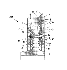
Figure 1 shows an embodiment of a rail wheel brake 100 with a rail wheel 1,
and friction ring bodies 10 are embodied according to the invention are
arranged at
the rail wheel 1. The rail wheel brake 1 has a wheel web 2 which extends in a
plate-
shaped way in a radial plane between a hub 3 and a rim 4, and a running
surface 5 is
situated at the wheel rim 4 which on the right side merges into a flange 6.
The rail
wheel 1 is therefore configured for rolling on a rail and may be part of the
chassis of a
railway vehicle. The rail wheel 1 is provided with friction ring bodies 10,
and friction
pads, which are not shown, are provided, which are brought into contact on the
out-
side with the friction ring bodies 10 for braking the rail wheel 1.
The friction ring bodies 10 are configured to run around the axis of the rail
wheel 1 in an annular manner and are dimensioned in such a way that the
friction ring
bodies 10 can be arranged on the wheel web 2 in the radially extending area
between
the wheel hub 3 and the rim 4. The friction ring bodies 10 have friction rings
11,
against which the brake pads (not shown) of the rail wheel brake 100 can be
pressed.
CA 02920060 2016-02-01
6
Furthermore, the friction ring bodies 10 comprise attachment bodies 12 and 13,
and
the attachment bodies 12 and 13 are arranged on the inner surface 14 of the
friction
rings 11, which faces toward the wheel web 2 and forms the opposite surface of
the
friction surface of the friction rings 11.
The attachment bodies 12 are configured as cooling elements 12 and pro-
trude into the ventilation gap 26 without touching the surface of the wheel
web 2.
The cooling elements 12 are configured lamellarly and are integrally bonded on
the
surface 14 of the friction rings 12.
The attachment bodies 13 form connection bodies 13 which are seated be-
tween the surface 14 of the friction rings 11 and the surface of the wheel web
2. Here,
the connection bodies 13 are planar seated or positively inserted in a recess
27 in the
surface 14 of the friction rings 11 and may there be also integrally bonded to
the fric-
tion rings 11.
The friction rings 11 and the attachment bodies 12 and 13 are each cut out
of flat metal material, for example by a laser cutting method, a water jet
cutting
method or by a thermal cutting process.
A screw element 16 extend through the wheel web 2, which is seated in re-
ceiving notches in the connection bodies 13 and connects the connection bodies
13
with each other on both sides of the wheel web 2. By the connection formed
with the
screw element 16 the friction ring bodies 10 are held positively at the wheel
web 2 of
the rail wheel 1.
On the right side of the wheel web 2 the connection body 13 is formed with
a notch 18 which extends in the radial direction of the rail wheel 1. A guide
member
20 is inserted into the notch 18, which is connected in a positive locking
with the
wheel web 2 via a clamping sleeve 21. Through the notch 18 longitudinally
extending
in radial direction, the guide member 20 can slide in the notch 18 to be able
to com-
pensate radial displacements of the friction ring 11, for example due to
thermal ef-
fects, wherein the guide member 20 is arranged in a fixed position at the
wheel web
2 by the clamping sleeve 21.
The screw element 16 has a screw shaft 22 having a smaller outer diameter
than the inner diameter of the clamping sleeve 21. This avoids any tensions
during a
radial expansion of the friction ring 11, which may cause a drift in the
position of the
screw element 16.
The guide element 20 in assembly in the notch 18 in the connector element
13 is shown only on the right side, and, distributed along the circumference
of the rail
CA 02920060 2016-02-01
7
wheel 1, several screw connections can be provided with the screw element 16
and
the clamping sleeve 21 together with the guide element 20. The arrangement of
the
guide element 20 and the clamping sleeve 21 can be provided alternately on the
left
and on the right side.
Figure 2 shows an exploded view of the rail wheel brake 100 with the rail
wheel 1, and in a flying arrangement the friction ring bodies 10 are shown
spaced
apart from the rail wheel 1 on both sides. In the bottom view of the friction
ring body
the attachment bodies 12 and 13 are visible, which are embodied once as a
cooling
element 12 and once as a connection body 13. Further shown are the screw
elements
16 to connect the friction ring bodies 10 with each other, and to connect them
with
the rail wheel 1. In the inside view of the lower friction ring 11, the
connection bodies
13 are shown with the notches 18, in which the guide elements 20 can be
seated, fur-
ther shown are the clamping sleeves 21, which can be inserted into holes in
the wheel
web 2. For a more detailed embodiment of the friction ring bodies 10 in the
following
figures 3a, 3b and 3c several variants are shown as described below.
Figures 3a, 3b and 3c respectively show rail wheel brakes 100 having a rail
wheel 1, a wheel web 2 in a radial plane of extension between a wheel hub 3
and a
wheel rim 4. On both sides of the wheel web 2 friction ring bodies 10 with
respective
friction rings 11 and attachment bodies 12 and 13 are arranged.
Figure 3a shows an embodiment in which the connection bodies 13 are ap-
plied in a planar manner to the inner surface 14 of the friction rings 11. For
fastening
the connection bodies 13, they can be applied in an integrally bonded
connection on
the surface 14, for example by a welding method or a soldering method.
Similarly, the
cooling elements 12 may be applied to the surface 14.
Figure 3b shows an embodiment for connecting the connection bodies 13
with the friction rings 11, wherein recesses 27 are provided on the surface
14, into
which the connection bodies 13 are inserted, so that in addition to a not
further
shown integrally bonded connection between the connection bodies 13 and the
fric-
tion rings 11 a positive connection is formed. On the right side of the wheel
web 2 the
connection body 13 is shown as an example with a notch 18 which is bounded by
a
side surface 19 of the notch 18, and it can be seen that the notch 18 runs in
radial di-
rection between the wheel hub 3 and the rim 4.
Figure 3c finally shows an embodiment for forming a connection between
the connection body 13 and the friction ring 11 in which holes 15 are cut into
the fric-
tion rings 11, through which the connection bodies 13 extend and are flush
with the
CA 02920060 2016-02-01
8
outer surface of the friction rings 11. By this, next to the not shown
integrally bonded
connection, a positive connection between the connection body 13 and the
friction
rings 11 is created. The example shows a notch 18 with a side surface 19 on
the left
side of the wheel web 2, while the connection body 13 on the right side does
not
show the notch.
Figure 4 shows a perspective view of a connection body 13 with a notch 18
which is laterally bounded by two side surfaces 19, and in the notch 18 a
guide mem-
ber 20 can be inserted according to figure 5. The connection body 13 has a
screw pas-
sageway 24, and the guide element 20 has a bore 25 for receiving the clamping
sleeve
21, wherein the inner diameter of the clamping sleeve 21 has a larger diameter
than
the screw shaft 22 of the screw element 16, see Figure 1. The screw passageway
24 in
the connection body 13 can form a fit with the diameter ranges at the ends of
the
screw element 16, so that a radial movement of the screw element 16 relative
to the
connection body 13 is prevented.
In order to slide the guide element 20 in the notch 18 in the connection
body 13 the guide element 20 is bounded by lateral guide surfaces 23, which
slide on
the side surfaces 19 of the notch 18 in the connection body 13.
The invention is not limited in its embodiment to the above-described pre-
ferred embodiment. Rather, a number of variants are conceivable, which make
use of
the described solution also for basically different embodiments. All features
and / or
advantages arising from the claims, the description or the figures, including
structural
details, spatial arrangements and process steps, can be essential to the
invention both
by themselves or in arbitrary combinations.
CA 02920060 2016-02-01
9
LIST OF REFERENCE NUMBERS
100 rail wheel brake
1 rail wheel
2 wheel web
3 hub
4 rim
running surface
6 flange
friction ring body
11 friction ring
12 attachment body, cooling element
13 attachment body, connection body
14 surface
hole
16 screw
17 notch
18 notch
19 side surface
guide element
21 clamping sleeve
22 screw shaft
23 guide surfaces
24 screw passageway
bore
26 ventilation gap
27 recess
Claims