Note: Descriptions are shown in the official language in which they were submitted.
CA 02920064 2016-02-05
¨1/17¨
A ROTATION-SUSPENSION SMELTING METHOD, A BURNER AND A
METALLURGICAL EQUIPMENT
FIELD OF THE INVENTION
[1] The invention relates to the field of nonferrous metallurgical technology,
in particular to a
method and an equipment for smelting metal sulfide concentrate comprising
copper, nickel, lead,
zinc and the like to obtain sulfur and even metal product.
BACKGROUND OF THE INVENTION
[2] In pyrometallurgy industry, smelting of sulfide concentrate is a
process to obtain metals by
eventually removing sulfur and iron in the sulfide ore through their reaction
with oxygen. The
pyro-metallurgy processes may be roughly divided into two broad categories,
including bath
smelting and spatial suspension smelting, in which the essence of spatial
suspension smelting is to
fully combine the material particles with oxygen by taking advantage of the
huge surface area of
the dried powdered sulfide ore, such that the oxidation reaction is completed
in a moment (2-3 s).
The most widely applied spatial levitation smelting is Outokumpu flash
smelting invented by
Finnish scientists in 1949, and the core process of which uses direct flow jet
technology. Due to
the effect from characteristics of direct flow, adverse situations such as low
utilization rate of
oxygen, high dust rate, serious furnace lining erosion-corrosion, formation of
raw material heap
resulted from accumulation of unreacted concentrate in the furnace and the
like often occur in the
production. As smelting technologies are developed towards the "four-high"
direction, i.e. high
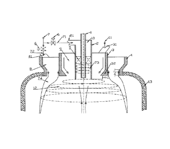
feeding amount, high load, high oxygen concentration and high operation rate,
it is increasingly
difficult for direct flow jet technology to meet the requirements for modern
pyro-metallurgy.
[3] In recent years, rotation-jet technology has been applied well in the pyro-
metallurgy industry,
for example, the method presented by Chinese patent No. 200910230500.3, but
situations
including serious wear of the equipments and reaction segregation due to
sorting of the concentrate
flow are encountered in the production using this method; improved schemes are
the methods as
presented by Chinese patents (Patent No. ZL 201020284998 and No.
201110208013.4), and both
methods include disposing the whole of the concentrate in an outer ring of a
reactive air swirl, and
propelling movement of particles of the concentrate by means of swirl
expansion to form a
high-speed rotating mixed swirl and to complete mass transfer and heat
transfer between the gas
80584282
34273/12
CA 02920064 2016-02-05
¨2/17 ¨
and the particles. However, the methods described above have the following
problems in the
production practices: since the entrainment outside the swirl is too large, a
large amount of
high-temperature off-gas after the reaction is caused to flow back to the top
of reaction tower,
rendering the depletion at the top of the reaction tower too rapid; for
individual concentrate
particles whose properties including physical specification, specific gravity
and chemical
composition vary greatly, the rotation intensity may be adjusted but is
difficult to control: it is not
enough to propel rotary motion of the particles if the rotation intensity is
too low, while flash
phenomenon occurs to damage the furnace body if the rotation intensity is too
high; as the reaction
gas diffuses from the inside out and reaches the outer ring of the material
circle, most oxygen has
been depleted, so that particles of the concentrate in the outer ring of the
material circle cannot be
oxidized.
SUMMARY OF THE INVENTION
[4] In view of above, the invention provides a novel rotation-suspension
smelting method to solve
the technical problems found in the above process schemes.
[5] The invention provides a rotation-suspension smelting burner for
implementing the above
method.
[6] The invention provides a metallurgical equipment using the above rotation-
suspension
smelting burner.
[7] To achieve the above objects, the invention provides a technical
solution as follows:
[8] a rotation-suspension smelting method, in which a dry powdered sulfide
concentrate and a
corresponding amount of an oxygen-containing gas are sprayed into a space
within a
high-temperature reaction tower, with a characteristic "wind-concentrate-wind"
arrangement on
the horizontal plane; wherein:
[9] the oxygen-containing gas includes the first oxygen-containing gas and the
second
oxygen-containing gas; the second oxygen-containing gas is sprayed vertically
down in the form
of an annular direct flow into the reaction tower, and forms in the reaction
tower a bell-shaped
wind curtain that gradually expands horizontally and extends vertically under
the effect of high
80584282
34273/12
CA 02920064 2016-02-05
¨3/17 ¨
temperature; and the first oxygen-containing gas is transformed into a
rotation-jet and jetted into
the center of the wind curtain;
[10] a metered amount of the dry sulfide concentrate enters an annular space
between the two gas
flows of the rotation-jet and the wind curtain, in a direction deviated
towards the central axis;
[11] in the center of the wind curtain, a circumferential expansion movement
of the rotation-jet
rotating at a high speed draws in the sulfide concentrate and a high-
temperature gas flow from the
bottom of the reaction tower simultaneously, forming a gas-particle two-phase
rotation-jet that
rotates and expands horizontally and moves down vertically; and
[12] during the movement process, the sulfide concentrate is ignited by a high-
temperature off-gas
and the high temperature radiated in the reaction tower, resulting in a
violent combustion reaction
with oxygen and release off 802-rich off-gas, at the same time, a mixed melt
containing matte (or
metal) and slag is produced from the reaction; and the matte (or metal) is
finally separated from
the slag at the bottom of the reaction tower, thereby completing the
metallurgical process.
[13] Preferably, the first oxygen-containing gas and the second oxygen-
containing gas are the same
reaction gas with the same pressure, temperature and oxygen content, wherein
the oxygen content
thereof is 25 wt% to 95 wt% 02.
[14] Preferably, the sum of the oxygen contained in the first oxygen-
containing gas and the second
oxygen-containing gas is the total amount required for the reaction of the
sulfide concentrate, the
distribution proportion being 20-80% (volume ratio).
[15] Preferably, the rotation-jet has a rotation strength > 0.5; and the
second oxygen-containing gas
has a speed of 30-200 m/s when entering the reaction tower.
[16] Preferably, the dry powdered sulfide concentrate refers to sorted ores
comprising metal
sulfides of Cu, Ni, Pb and/or Zn.
[17] As can be seen from the above technical solution, the rotation-suspension
smelting method
provided by the invention involves disposing the sulfide concentrate between
two layers of
oxygen-containing reaction gas, and drawing in the sulfide concentrate and the
high-temperature
gas flow from the bottom of the reaction tower simultaneously by means of the
80584282
34273/12
CA 02920064 2016-02-05
¨4/17 ¨
circumferential expansion movement of the oxygen-containing gas in the middle
that rotates at a
high speed, to form a gas-particle two-phase rotation-jet that rotates and
expands horizontally and
moves down vertically. When the gas-particle two-phase rotation-jet expands
outwards and
reaches the inner curtain wall of the wind curtain, its further disordered
outward expansion is
prevented under the control of the gathering effect of the wind curtain,
thereby eliminating the
flash phenomenon; the wind curtain supplements the gas-particle two-phase
rotation-jet in the
outer ring thereof with the wind entrainment amount required for the outside
uninterruptedly to
compensate for the oxygen potential in the outer ring of the gas-particle two-
phase rotation-jet,
and to prevent a large amount of high-temperature off-gas after the reaction
from flowing back to
the top of the reaction tower which would cause the depletion at the top of
the reaction tower too
rapid; what is more beneficial is that the convergence of the two gas flows
form a violent turbulent
flow, which renders the motion trajectory of particles of the concentrate in
the space random and
disordered and facilitates the collision between particles of the concentrate,
thereby providing
dynamic conditions for the mass transfer and heat transfer between particles
of the concentrate.
[18] To achieve the above process object, the invention also provides a
rotation-suspension
smelting burner, which has a cylindrical structure fitted together, including:
a tubular auxiliary
nozzle located on the central axis; a cylindrical cyclone fitted around the
auxiliary nozzle; a guide
vane located between the cyclone and the nozzle; a feeding pipe fitted around
the cyclone; and a
wind pipe fitted around the feeding pipe;
[19] wherein a rotation passage is formed between the outer pipe wall of the
nozzle and the inner
pipe wall of the cyclone; a feeding cavity that gradually contracts at the
bottom and deviates
towards the central axis is formed between the outer pipe wall of the cyclone
and the inner pipe
wall of the feeding pipe; and a gas chamber having a straight-pipe segment at
the bottom is formed
between the outer pipe wall of the feeding pipe and the inner wall of the wind
pipe.
[20] Preferably, the outlet plane of the nozzle is inside the outlet plane of
the cyclone, and the
outlet plane of the cyclone exceeds the outlet plane of the feeding pipe by a
height hl of 30 to 100
mm.
[21] Preferably, the inner wall of the outlet of the feeding pipe is a bluff
body that gradually
contracts in the direction towards the central axis.
80584282
34273/12
CA 02920064 2016-02-05
¨5/17¨
[22] Preferably, the outlet of the wind pipe is a straight-pipe segment having
a straight-pipe length
h2 of 100 to 400 mm.
[23] Preferably, a regulating valve for distributing the flow ratio of the
oxygen-containing gas is
further included.
[24] The inlets of the rotation passage and the gas chamber are both connected
to a gas source of
the oxygen-containing gas through a pipe with a regulating valve installed
thereon.
[25] Preferably, the gas chamber has a funnel shape with a cross-sectional
area of the inlet larger
than that of the outlet.
[26] The invention also provides a metallurgical equipment including a
reaction tower and a
rotation-suspension smelting burner which is the rotation-suspension smelting
burner described
above.
[27] The invention has the following beneficial effects:
[28] firstly, the utilization rate of oxygen is high, and the materials are
reacted fully with oxygen;
[29] secondly, the high probability of collision between particles of the
concentrate facilitates the
settlement after the reaction, leading to a low dust generation rate;
[30] thirdly, the large capacity can meet the requirements for wide
fluctuations in feeding amount,
allowing a low energy consumption and a small investment;
[31] fourthly, the flash phenomenon of the rotation and the backflow
phenomenon of a large
amount of high-temperature off-gas in the outer ring are eliminated, allowing
a small space
required for the reaction, no dead reaction zones, and a minimal erosion
effect on the refractory of
the furnace body; and
[32] fifthly, the construction is simple, which is convenient and reliable in
terms of the control,
operation and maintenance, and runs at a low cost by fully utilizing the
potential energy of the
fluid.
8058428.2
34273/12
CA 02920064 2016-02-05
¨6/17 ¨
DESCRIPTION OF THE DRAWINGS
[33] To explain the examples of the invention or the technical solutions in
the prior art more clearly,
the drawings that are needed to describe the examples or the prior art are
introduced briefly below;
apparently, the drawings described below are only certain examples of the
invention, and for those
ordinary skilled in the art, other drawings may also be obtained according to
these drawings on the
premise of no creative work.
[34] Figure 1 is a schematic diagram of a process scheme and a construction of
a metallurgical
equipment provided according to an example of the invention.
[35] Figure 2 is a schematic top view of the metallurgical equipment provided
according to an
example of the invention.
[36] In the figures, 1 is a nozzle; 2 is a cyclone and 21 is a first wind
inlet; 3 is a feeding pipe, 31 is
a second feeding inlet, and 32 is a bluff body; 4 is a wind pipe and 41 is a
third wind inlet; 5 is a
guide vane; 6 is a regulating valve; 7 is an oxygen-containing gas, 71 is a
first oxygen-containing
gas, and 72 is a second oxygen-containing gas, 73 is a rotation-jet, and 74 is
an wind curtain; 8 is a
gas chamber; 9 is a feeding cavity; 10 is a rotation passage; 11 is a
concentrate; 12 is a two-phase
rotation- jet; and 13 is a reaction tower.
DETAILED DESCRIPTION OF THE INVENTION
[37] The invention provides a novel rotation-suspension smelting method to
improve oxygen
utilization rate and to allow the materials to react fully with oxygen; which
method eliminates the
flash phenomenon of the swirl and the backflow phenomenon of a large amount of
high-temperature off-gas in the outer ring, allowing a small space required
for the reaction, no
dead reaction zones, and a minimal erosion effect on the refractory of the
furnace body. The
invention provides a rotation-suspension smelting burner to implement the
above method, and a
metallurgical equipment using the above burner.
[38] The technical solutions according to examples of the invention are
described clearly and fully
80584282
34273/12
CA 02920064 2016-02-05
¨7/17 ¨
below with reference to the drawings in the examples of the invention.
Apparently, the examples
described are only part of the examples according to the invention, rather
than all of examples. All
the other examples obtained by those ordinary skilled in the art on the
premise of no creative work,
based on the examples according to the invention, fall within the scope
claimed by the invention.
[39] Please refer to Figure 1 and Figure 2. Figure 1 is a schematic diagram of
a process scheme and
a construction of a metallurgical equipment provided according to an example
of the invention;
and Figure 2 is a schematic top view of a metallurgical equipment provided
according to an
example of the invention.
[40] The rotation-suspension smelting method provided according to an example
of the invention
has core improvements in that: a dry powdered sulfide concentrate 11 and a
corresponding amount
of an oxygen-containing gas 7 are sprayed into a space within a high-
temperature reaction tower
13, with a characteristic "wind-concentrate-wind" arrangement on the
horizontal plane; wherein:
[41] the oxygen-containing gas 7 includes a first oxygen-containing gas 71 and
a second
oxygen-containing gas 72, in which the second oxygen-containing gas 72 is
sprayed vertically
down in the form of an annular direct flow into the reaction tower 13 and
forms in the reaction
tower 13 a bell-shaped wind curtain 74 that gradually expands horizontally and
extends vertically
under the effect of high temperature; and the first oxygen-containing gas 71
is transformed into a
rotation-jet 73 and jetted vertically down into the center of the wind curtain
74;
[42] a metered amount of the dry sulfide concentrate 11 falls freely and
vertically, and enters from
the top downward an annular space between the two gas flows of the rotation-
jet 73 and the wind
curtain 74, in a direction deviated towards the central axis;
[43] in the center of the wind curtain 74, a circumferential expansion
movement of the rotation-jet
73 rotating at a high speed draws in the sulfide concentrate 11 and a high-
temperature gas flow
from the bottom of the reaction tower 13 simultaneously, forming a gas-
particle two-phase
rotation-jet 12 that rotates and expands horizontally and moves down
vertically; and the
construction thereof can be seen in Figure 1;
[44] during the movement process, the sulfide concentrate 11 is ignited by a
high-temperature
off-gas and the high temperature radiated in the reaction tower 13, resulting
in a violent
combustion reaction with oxygen and release of S02-rich off-gas, at the same
time, a mixed melt
containing matte (or metal) and slag is produced from the reaction; and the
matte (or metal) is
8058428.2
34273/12
CA 02920064 2016-02-05
¨8/17 ¨
finally separated from the slag at the bottom of the reaction tower 13,
thereby completing the
metallurgical process.
[45] As can be seen from the above technical solution, the rotation-suspension
smelting method
provided according to the example of the invention involves disposing the
sulfide concentrate 11
between two layers of oxygen-containing reaction gas, and drawing in the
sulfide concentrate 11
and the high-temperature gas flow from the bottom of the reaction tower 13
simultaneously by
means of the circumferential expansion movement of the oxygen-containing gas
(i.e. rotation-jet
73) in the middle that rotates at a high speed, to form a gas-particle two-
phase rotation-jet 12 that
rotates and expands horizontally and moves down vertically. When the gas-
particle two-phase
rotation-jet 12 expands outwards and reaches the inner curtain wall of the
wind curtain 74, its
further disordered outward expansion is prevented under the control of the
gathering effect of the
wind curtain 74, thereby eliminating the flash phenomenon; the wind curtain 74
supplements the
gas-particle two-phase rotation-jet 12 in the outer ring thereof with the wind
entrainment amount
required for the outside uninterruptedly to compensate for the oxygen
potential in the outer ring of
the gas-particle two-phase rotation-jet 12, and to prevent a large amount of
high-temperature
off-gas after the reaction from flowing back to the top of the reaction tower
13 which would cause
the depletion at the top of the reaction tower 13 too rapid; what is more
beneficial is that the
convergence of the two gas flows form a violent turbulent flow, which renders
the motion
trajectory of particles of the concentrate 11 in the space random and
disordered and facilitates the
collision between particles of the concentrate 11, thereby providing dynamic
conditions for the
mass transfer and heat transfer between particles of the concentrate 11.
[46] The properties of the oxygen-containing gas 7 can be determined by those
skilled in the art
according to the practical process requirements. In a specific example
provided according to the
present embodiment, the first oxygen-containing gas 71 and the second oxygen-
containing gas 72
are the same reaction gas with the same pressure, temperature and oxygen
content, their oxygen
content being 25 wt% to 95 wt%. As such, the first oxygen-containing gas 71
and the second
oxygen-containing gas 72 may be provided by the same gas source, helping to
simplify the
construction of the metallurgical equipment.
[47] To further optimize the above technical solution, the sum of the oxygen
comprised in the first
80584282
34273/12
CA 02920064 2016-02-05
¨9/17 ¨
oxygen-containing gas 71 and the second oxygen-containing gas 72 is the total
amount required
for reaction of the sulfide concentrate 11, with the distribution proportion
being 20-80% (volume
ratio). The specific way of distribution is determined according to actual
situations and is not
limited herein.
[48] Preferably, the first oxygen-containing gas 71 is transformed into the
rotation-jet 73 having a
rotation strength > 0.5 through an axially mounted guide vane 5; and the
second
oxygen-containing gas 72 is a vertically downward direct flow having a speed
of 30 to 200 m/s at
the burner outlet (that is, when entering the reaction tower 13) for purpose
of achieving a better
effect of the rotation-suspension smelting reaction.
[49] In a specific example provided according to the present embodiment, the
dry powdered sulfide
concentrate 11 refers to sorted ores comprising metal sulfides of Cu, Ni, Pb
and/or Zn, and the
like.
[50] To achieve the above process objects, an example according to the
invention also provide a
rotation-suspension smelting burner for being installed downward vertically in
the hole at the top
of the obconical reaction tower 13, the core improvements of which are in
that: the
rotation-suspension smelting burner has a cylindrical structure fitted
together, including: from the
inside out, a tubular auxiliary nozzle 1 located on the central axis; a
cylindrical cyclone 2 fitted
around the auxiliary nozzle I; an axially mounted guide vane 5 located between
the cyclone 2 and
the nozzle 1; a feeding pipe 3 fitted around the cyclone 2; and a wind pipe 4
fitted around the
feeding pipe 3;
[51] wherein a rotation passage 10 is formed between the outer pipe wall of
the nozzle 1 and the
inner pipe wall of the cyclone 2; a feeding cavity 9 that gradually contracts
at the bottom and
deviates towards the central axis is formed between the outer pipe wall of the
cyclone 2 and the
inner pipe wall of the feeding pipe 3; and a gas chamber 8 having a straight-
pipe segment at the
bottom is formed between the outer pipe wall of the feeding pipe 3 and the
inner wall of the wind
pipe 4.
[52] Preferably, the guide vane 5 is mounted axially on the outer wall of the
nozzle 1, and is
located in the middle part of the length of the cyclone 2 to obtain the
rotation-jet 73 suitable for the
80584282
34273/12
CA 02920064 2016-02-05
¨10/17 ¨
rotation-suspension smelting reaction. To further optimize the above technical
solution, the outlet
plane of the nozzle 1 is inside the outlet plane of the cyclone 2, and as
shown in Figure 1, in a
vertical direction, the outlet at the bottom of the nozzle 1 is above the
outlet of the cyclone 2; the
outlet plane of the cyclone 2 exceeds the outlet plane of the feeding pipe 3
by a height hl of 30 to
100 mm, that is, in a vertical direction, the outlet at the bottom of the
cyclone 2 is 30 to 100 mm
lower than the outlet of the feeding pipe 3; and the outlets at the bottoms of
the feeding pipe 3 and
the wind pipe 4 may be of same level. By the above construction design, both
the way and the
timing for the reaction materials to enter the reaction tower 13 are
optimized, thus a better effect of
the rotation-suspension smelting reaction can be obtained.
[53] In a specific example provided according to the present embodiment, the
inner wall of the
outlet of the feeding pipe 3 is an annularly disposed bluff body 32 that
gradually contracts in the
direction towards the central axis, and the outer pipe of the cyclone 2 is a
round pipe with a
vertically uniform diameter (the structure of which may be seen with reference
to figure 1), thus
serving to decelerate and guide the concentrate 11.
[54] Preferably, the outlet of the wind pipe 4 is a straight-pipe segment
having a straight-pipe
length h2 of 100 to 400 mm to ensure that the second oxygen-containing gas 72
can be sprayed
vertically down in the form of an annular direct flow into the reaction tower,
and be formed into a
bell-shaped wind curtain 74 that gradually expands horizontally and extends
vertically.
[55] The rotation-suspension smelting burner provided according to an example
of the invention
also includes a regulating valve 6 for distributing the flow ratio of the
oxygen-containing gas 7.
[56] The inlets of the rotation passage 10 and the gas chamber 8 are both
connected to a gas source
of the oxygen-containing gas 7 through a pipe with the regulating valve 6
installed on the pipe.
The number of the regulating valve 6 may be one or two; when one regulating
valve is used, the
flow ratio can be adjusted by installing it on any one of the branched pipes;
in a specific example
provided according to the present embodiment, two regulating valves 6 are used
and installed on
the gas-intake branched pipes of the first oxygen-containing gas 71 and the
second
oxygen-containing gas 72, respectively, the construction thereof may be seen
with reference to
figure 1.
8058428.2
34273/12
CA 02920064 2016-02-05
¨11/17¨
[57] The number of the first wind inlet(s) 21 for connecting the outlet of the
gas source and the
inlet of the rotation passage 10, which are installed at the upper part of the
cyclone 2, may be 1, 2
or 3, or the like. Preferably, a plurality of the first wind inlets 21
described above are distributed
evenly in the circumferential direction of the cyclone 2, and the gas-intake
direction is
perpendicular to the axial direction of the cyclone 2.
[58] The number of the second feeding inlets 31 for inward feeding and
connecting with the inlet
of the feeding cavity 9, which are installed symmetrically at the upper part
of the feeding pipe 3,
may be an even number, for example, 2, 4, 6 or the like. Preferably, the gas-
intake direction of the
second feeding inlets 31 described above is oriented towards the direction of
the central axis of the
feeding pipe 3.
[59] The number of the third wind inlets 41 for connecting the outlet of the
gas source and the inlet
of the gas chamber 8, which are installed symmetrically at the top of the wind
pipe 4, may be an
even number, for example, 2, 4, 6 or the like. Preferably, the gas-intake
direction of the third
feeding inlets 41 described above is oriented towards the direction of the
central axis of the wind
pipe 4, and the construction thereof may be seen with reference to figure 2.
[60] Further, the gas chamber 8 has a funnel shape with a cross-sectional area
of the inlet larger
than that of the outlet. As shown in figure 1, the internal diameter of the
inlet of the wind pipe 4 is
larger than that of its outlet, and there is a slope oriented towards the
direction of the central axis
between the inlet and the outlet, that is, the inner pipe wall of the wind
pipe 4 is funnel-shaped;
and the outer pipe wall of the feeding pipe 3 has a regular circumferential
surface, thus forming a
funnel-shaped gas chamber 8 between the outer pipe wall of the feeding pipe 3
and the inner pipe
wall of the wind pipe 4, such a structure that is large at the upper part and
small at the lower part
serves to accelerate the rate of the second oxygen-containing gas 72 flowing
therein.
[61] The burner provided according to the present embodiment is further
explained below in
combination with a specific operating process.
[62] As shown in Figure 1, after the feeding amount is determined, the dry
powdered sulfide
8058428.2
34273/12
CA 02920064 2016-02-05
¨12/17 ¨
concentrate 11 and a corresponding amount of the oxygen-containing gas 7 are
sprayed into the
space in the high-temperature reaction tower 13 through the above rotation-
suspension smelting
burner, which presents a "wind-concentrate-wind" arrangement feature on the
horizontal plane, in
which:
[63] before the oxygen-containing gas 7 is sent to the equipment via a pipe,
the pipe is bifurcated
into two branches, and the corresponding oxygen-containing gas 7 is divided
into two parts, the
first oxygen-containing gas 71 and the second oxygen-containing gas 72, in
which the second
oxygen-containing gas 72 is sprayed in the form of an annular direct flow
through the gas chamber
8 of the nozzle into the reaction tower 13; and the first oxygen-containing
gas 71 passes through
the cyclone 2, and is transformed into the rotation-jet 73 by the guide vanes
5 and jetted into the
center of the annular direct flow of the second oxygen-containing gas 72.
[64] A metered amount of the dry sulfide concentrate 11 falls freely and
vertically through the
annular passage feeding cavity 9 of the nozzle, and at the outlet of the
annular passage feeding
cavity 9, enters the annular space between the two gas flows in a direction
deviated towards the
central axis under the decelerating and guiding effect of the annularly
disposed bluff body 32
inclining towards the axis.
[65] After leaving the burner and entering the reaction tower 13, the annular
direct flow of the
second oxygen-containing gas 72 is mainly affected by the high temperature in
the reaction tower
13 and forms a bell-shaped wind curtain 74 that gradually expanded
horizontally and extended
vertically in the space of the reaction tower 13; and in the center of the
wind curtain 74, the sulfide
concentrate 11 and the high-temperature gas flow from the bottom of the
reaction tower 13 are
drawn in simultaneously by means of the circumferential expansion movement of
the
oxygen-containing gas (i.e. rotation-jet 73) that rotates at a high speed,
leading to formation of a
gas-particle two-phase rotation-jet 12 that rotates and expands horizontally
and moves down
vertically.
[66] When the gas-particle two-phase rotation-jet 12 expands outwards and
reaches the inner
curtain wall of the wind curtain 74, its further disordered outward expansion
is prevented under the
control of the gathering effect of the wind curtain 74, thereby eliminating
the flash phenomenon;
the wind curtain 74 supplements the gas-particle two-phase rotation-jet 12 in
the outer ring thereof
80584282
34273/12
CA 02920064 2016-02-05
-13/17-
with the wind entrainment amount required for the outside uninterruptedly to
compensate for the
oxygen potential in the outer ring of the gas-particle two-phase rotation-jet
12, and to prevent a
large amount of high-temperature off-gas after the reaction from flowing back
to the top of the
reaction tower which would cause the depletion at the top of the reaction
tower too rapid; what is
more beneficial is that the convergence of the two gas flows form a violent
turbulent flow, which
renders the motion trajectory of particles of the concentrate 11 in the space
random and disordered
and facilitates the collision between particles of the concentrate 11, thereby
providing dynamic
conditions for the mass transfer and heat transfer between particles of the
concentrate 11.
[67] During the movement process, the sulfide concentrate 11 is ignited by the
high-temperature
off-gas and the high temperature radiated in the reaction tower 13, resulting
in a violent
combustion reaction with oxygen and release of S02-rich off-gas, at the same
time, a mixed melt
containing matte (or metal) and slag is produced from the reaction; and the
matte (or metal) is
finally separated from the slag at the bottom of the reaction tower 13,
thereby completing the
metallurgical process.
[68] An example according to the invention also provide a metallurgical
equipment, including the
reaction tower 13 and a rotation-suspension smelting burner, and the core
improvements of which
are in that: the rotation-suspension smelting burner is the above rotation-
suspension smelting
burner installed vertically downward in the hole at the top of the obconical
reaction tower 13.
[69] To sum up, the example according to the invention provides a method for
rotation-suspension
smelting sulfide concentrate powder, in which the dry powdered sulfide
concentrate 11 and a
corresponding amount of the oxygen-containing gas 7 are sprayed into the space
of the
high-temperature reaction tower 13 through an equipment. The oxygen-containing
gas 7 is divided
into two parts, i.e. the first oxygen-containing gas 71 and the second oxygen-
containing gas 72,
before entering the equipment. The second oxygen-containing gas 72 is sprayed
in the form of an
annular direct flow into the reaction tower 13 and forms a bell-shaped wind
curtain 74; and the
first oxygen-containing gas 71 is transformed into the rotation-jet 73 via the
equipment and jetted
into the center of the wind curtain 74. In the annular space between the two
gas flows, the
concentrate 11 entering in a direction deviated towards the center is drawn in
the rotation-jet 73,
and the high-temperature off-gas from the bottom of the reaction tower 13 is
also sucked in,
80584282
34273/12
CA 02920064 2016-02-05
¨14/17 ¨
forming a gas-particle mixed two-phase rotation-jet 12. The sulfide
concentrate 11 is ignited by the
high temperature, namely, starting a violent combustion reaction with oxygen
and releasing
S02-rich off-gas, at the same time, a mixed melt containing matte (or metal)
and slag is formed;
and the matte (or metal) is finally separated from the slag at the bottom of
the reaction tower 13,
thereby completing the metallurgical process. To achieve the process object,
the invention also
provides a metallurgical equipment and a rotation-suspension smelting burner
thereof.
[70] Each example in the present specification is described in a progressive
way; all that each
example highlights are the differences from other examples, and the same or
similar parts among
respective example may refer to each other.
[71] The above descriptions of the disclosed examples can allow those skilled
in the art to
implement or use the invention. Various modifications to these examples are
apparent to those
skilled in the art, and the general principle defined herein may be
implemented in other examples
without departing from the spirit or scope of the invention. Therefore, the
invention shall not be
limited to these examples illustrated herein, but corresponds to the broadest
scope consistent with
the principle and novel features disclosed herein.
8058428.2
34273/12