Note: Descriptions are shown in the official language in which they were submitted.
CA 02920254 2016-02-02
WO 2015/020986 PCT/US2014/049665
PROVIDING DIAGNOSTIC AND/OR PROGNOSTIC CAPABILITIES IN A
PROCESS CONTROL SYSTEM
FIELD OF THE DISCLOSURE
[0001] The present disclosure is directed to process control systems and, more
particularly, providing diagnostic and/or prognostic capabilities in a process
control
system.
BACKGROUND
[0002] Process control systems, such as distributed or scalable process
control
systems like those used in chemical, petroleum or other processes, typically
include
one or more process controllers communicatively coupled to one or more field
devices via analog, digital, or combined analog/digital buses. The field
devices,
which may include, for example, control valve assemblies (e.g., control
valves,
actuators, valve controllers), valve positioners, switches, and transmitters
(e.g.,
temperature, pressure and flow rate sensors), perform functions within the
process
such as opening or closing valves, measuring process parameters, and
performing
basic diagnostics (e.g., valve controllers may estimate the real time mass of
fluid
flowing through the process for the purpose of detecting leaks). The process
controller receives signals indicative of process measurements made by the
field
devices and/or other information pertaining to the field devices, and uses
this
information to execute or implement one or more control routines to generate
control
signals, which are sent over the buses to the field devices to control the
operation of
the process. Information from each of the field devices and the controller is
typically
made available to one or more applications executed by one or more other
hardware
devices, such as host or user workstations, personal computers or computing
devices, to enable an operator to perform any desired function regarding the
process, such as setting parameters for the process, viewing the current state
of the
process, modifying the operation of the process, etc.
1
SUMMARY
[0003] One aspect of the present disclosure includes a process control device.
The process control device includes a process control valve, an actuator, and
a
digital valve controller. The actuator is coupled to the process control valve
and is
configured to control a position of the process control valve by controlling
the
pressure of a pressurized fluid utility medium. The digital valve controller
is
communicatively coupled to the process control valve and the actuator. The
digital
valve controller is configured to obtain first data and second data, the first
data
associated with a fluid flow through the actuator or the digital valve
controller at a
first point in time, and the second data associated with the fluid flow
through the
actuator or the digital valve controller at a second point in time different
from the first
point in time. A processor is arranged to aggregate the first data and the
second
data, and perform one or more diagnostic and/or prognostic techniques. The one
or
more diagnostic and/or prognostic techniques may, for example, include
estimating a
state of one or more components of the process control device.
[0003a] In one aspect of the invention, there is provided a process control
device,
comprising: a process control valve; an actuator coupled to the process
control valve
and configured to control a position of the process control valve, the
actuator
comprising an actuator body coupled to the process control valve, an actuator
casing
coupled to the actuator body and comprising upper and lower casings, and a
diaphragm secured between the upper and lower casings; a digital valve
controller
communicatively coupled to the process control valve and the actuator, the
digital
valve controller comprising a module base, a current to pressure converter
disposed
in the module base, and a pneumatic relay disposed within the module base in
fluid
communication with both the current to pressure converter and the actuator,
wherein
the digital valve controller is configured to: obtain first data associated
with a fluid
flow through the pneumatic relay of the digital valve controller at a first
point in time,
the first data comprising data indicative of a mass, a volume, and fluid
quality of the
fluid flow through the pneumatic relay at the first point in time, and obtain
second
data associated with the fluid flow through the pneumatic relay of the digital
valve
controller at a second point in time different from the first point in time,
the second
2
Date recue/date received 2021-10-26
data comprising data indicative of the mass, the volume, and the fluid quality
of the
fluid flow through the pneumatic relay at the second point in time; and a
processor
arranged to: aggregate the first data and the second data, and perform one or
more
diagnostic techniques, one or more prognostic techniques, or a combination of
the
one or more diagnostic and the one or more prognostic techniques based on the
aggregated data, the one or more diagnostic techniques, the one or more
prognostic
techniques, or the combination of the one or more diagnostic and the one or
more
prognostic techniques including assessing a physical integrity of the
diaphragm
based on the aggregated data, wherein the one or more diagnostic techniques,
the
one or more prognostic techniques, or the combination of the one or more
diagnostic
and the one or more prognostic techniques further include analyzing a total
level of
fluid mass, fluid volume, pollutants, particulates, moisture, or combinations
thereof,
that has flowed through the digital valve controller.
[0003b] In another aspect of the invention, there is provided a method of
providing
diagnostic, prognostic, or a combination of diagnostic and prognostic
techniques in
connection with a process control device comprising an actuator and a digital
valve
controller communicatively coupled to the actuator, the actuator comprising an
actuator body, an actuator casing coupled to the actuator body and comprising
upper
and lower casings, and a diaphragm secured between the upper and lower
casings,
the digital valve controller including a module base, a memory disposed within
the
module base, a processor disposed within the module base, logic stored on the
memory, a current to pressure converter disposed within the module base, and a
pneumatic relay disposed within the module base in fluid communication with
both
the current to pressure converter and the actuator, the method comprising:
obtaining,
via the digital valve controller, first data associated with a fluid flow
through the
pneumatic relay of the digital valve controller at a first point in time, the
first data
comprising data indicative of a mass, a volume, and fluid quality of the fluid
flow
through the pneumatic relay at the first point in time; obtaining, via the
digital valve
controller, second data associated with the fluid flow through the pneumatic
relay of
the digital valve controller at a second point in time, the second data
comprising data
indicative of a mass, a volume, and fluid quality of the fluid flow through
the
pneumatic relay at the second point in time; summing, via the digital valve
controller,
2a
Date recue/date received 2021-10-26
the first data and the second data; and performing one or more diagnostic
techniques, one or more prognostic techniques, or a combination of the one or
more
diagnostic and the one or more prognostic techniques based on the summing, the
one or more diagnostic techniques, the one or more prognostic techniques, or
the
combination of the one or more diagnostic and the one or more prognostic
techniques including assessing a physical integrity of the diaphragm based on
the
summing, wherein the one or more diagnostic techniques, the one or more
prognostic techniques, or the combination of the one or more diagnostic and
the one
or more prognostic techniques further include analyzing a total level of fluid
mass,
fluid volume, pollutants, particulates, moisture, or combinations thereof,
that has
flowed through the digital valve controller.
[0003c] In another aspect of the invention, there is provided a digital valve
controller communicatively coupled to a process control device comprising a
process
control valve and an actuator coupled to the process control valve and
configured to
control a position of the process control valve, the actuator comprising an
actuator
body, an actuator casing coupled to the actuator body and comprising upper and
lower casings, and a diaphragm secured between the upper and lower casings,
the
digital valve controller comprising: a module base; a memory disposed within
the
module base; a processor disposed within the module base; logic stored on the
memory; a current to pressure converter disposed within the module base; and a
pneumatic relay disposed within the module base in fluid communication with
the
current to pressure converter and the actuator, wherein the processor is
configured
to execute the logic to cause the processor to: obtain first data associated
with a fluid
flow through the pneumatic relay of the digital valve controller at a first
point in time,
the first data comprising data indicative of a mass, a volume, and fluid
quality of the
fluid flow through the pneumatic relay at the first point in time; obtain
second data
associated with the fluid flow through the pneumatic relay of the digital
valve
controller at a second point in time, the second data comprising data
indicative of a
mass, a volume, and fluid quality of the fluid flow through the pneumatic
relay at the
second point in time; aggregate the first data and the second data; and
perform one
or more diagnostic techniques, one or more prognostic techniques, or a
combination
of the one or more diagnostic and the one or more prognostic techniques based
on
2b
Date recue/date received 2021-10-26
the aggregated data, the one or more diagnostic techniques, the one or more
prognostic techniques, or the combination of the one or more diagnostic and
the one
or more prognostic techniques including assessing a physical integrity of the
diaphragm based on the aggregated data, wherein the one or more diagnostic
techniques, the one or more prognostic techniques, or the combination of the
one or
more diagnostic and the one or more prognostic techniques further include
analyzing
a total level of fluid mass, fluid volume, pollutants, particulates, moisture,
or
combinations thereof, that has flowed through the digital valve controller.
BRIEF DESCRIPTION OF THE DRAWINGS
[0004] FIG.1 is a schematic representation of a process control system having
one or more field devices constructed in accordance with the principles of the
present disclosure.
[0005] FIG.2 depicts one example of a field device constructed in accordance
with
the principles of the present disclosure.
[0006] FIG.3 is a cross-sectional view of the control valve, the actuator, and
the
digital valve controller of the field device of FIG.2.
[0007] FIG. 4 is a process flow chart showing one version of a method for
providing diagnostic and/or prognostic capabilities in connection with a
process
control system in accordance with the present disclosure.
DETAILED DESCRIPTION
[0008] Over time, high levels of fluid flow and high levels of pollutants,
particulates, and moisture in a fluid flow can damage and/or reduce the
effectiveness
of a process control device. For example, when pollutants and/or a significant
mass
2c
Date recue/date received 2021-10-26
CA 02920254 2016-02-02
WO 2015/020986 PCT/US2014/049665
or volume of fluid flow through one or more components of the process control
device, the pollutants and/or significant masses or volumes of fluid contact,
and may
crack or otherwise damage, those components, particularly elastomeric
components
in the process control device. These types of fluid flow can shorten the
lifespan
and/or hinder the performance of components in the process control device.
Likewise, particulates (e.g., dust, minerals) in or with the fluid flowing
through the
process control device can erode or abrade adjacent surfaces, particularly
adjacent
surfaces manufactured from "soft" materials like aluminum, brass, rubber, etc.
This
erosion can, in turn, significantly reduce the lifespan of components that
include
these surfaces. Moreover, fluid that includes particulates and/or significant
moisture
may, over time, deposit these particulates and/or other materials on, in, or
adjacent
to critical flow components such as nozzles, ports, relays, other accessories,
thereby
inhibiting the flow adjacent or through these components.
[0009] To reduce these undesirable effects, the present disclosure is directed
to
obtaining and aggregating data associated with fluid flowing through a process
control device. The present disclosure is directed to providing, based on the
obtained and/or aggregated data, diagnostic and/or prognostic capabilities in
connection with one or more components of a process control device that are
directly
exposed to or otherwise affected by fluid flow through the process control
device,
and, as such, are susceptible to the damage described above. The diagnostic
capabilities provided by the present disclosure may, for example, facilitate
quick and
easy monitoring and/or troubleshooting of these components. The prognostic
capabilities provided by the present disclosure may, for example, facilitate
the
calculation or estimation of future performance.
[0010] Referring now to FIG.1, a process control system 10 constructed in
accordance with one version of the present disclosure is depicted
incorporating one
or more field devices 15, 16, 17, 18, 19, 20, 21, 22, and 71 in communication
with a
process controller 11, which in turn, is in communication with a data
historian 12 and
one or more user workstations 13, each having a display screen 14. So
configured,
the controller 11 delivers signals to and receives signals from the field
devices 15,
3
CA 02920254 2016-02-02
WO 2015/020986 PCT/US2014/049665
16, 17, 18, 19, 20, 21, 22, and 71 and the workstations 13 to control the
process
control system.
[0011] In additional detail, the process controller 11 of the process
control system
of the version depicted in FIG.1 is connected via hardwired communication
connections to field devices 15, 16, 17, 18, 19, 20, 21, and 22 via
input/output (I/O)
cards 26 and 28. The data historian 12 may be any desired type of data
collection
unit having any desired type of memory and any desired or known software,
hardware or firmware for storing data. Moreover, while the data historian 12
is
illustrated as a separate device in FIG.1, it may instead or in addition be
part of one
of the workstations 13 or another computer device, such as a server. The
controller
11, which may be, by way of example, a DeltaVTM controller sold by Emerson
Process Management, is communicatively connected to the workstations 13 and to
the data historian 12 via a communication network 29 which may be, for
example, an
Ethernet connection.
[0012] As mentioned, the controller 11 is illustrated as being
communicatively
connected to the field devices 15, 16, 17, 18, 19, 20, 21, and 22 using a
hardwired
communication scheme which may include the use of any desired hardware,
software and/or firmware to implement hardwired communications, including, for
example, standard 4-20 mA communications, and/or any communications using any
smart communication protocol such as the FOUNDATION Fieldbus communication
protocol, the HART communication protocol, etc. The field devices 15, 16, 17,
18,
19, 20, 21, and 22 may be any types of devices, such as sensors, control valve
assemblies, transmitters, positioners, etc., while the I/O cards 26 and 28 may
be any
types of I/O devices conforming to any desired communication or controller
protocol.
In the embodiment illustrated in FIG.1, the field devices 15, 16, 17, 18 are
standard
4-20 mA devices that communicate over analog lines to the I/O card 26, while
the
digital field devices 19, 20, 21, 22 can be smart devices, such as HART
communicating devices and Fieldbus field devices, that communicate over a
digital
bus to the I/O card 28 using Fieldbus protocol communications. Of course, the
field
devices 15, 16, 17, 18, 19, 20, 21, and 22 may conform to any other desired
4
CA 02920254 2016-02-02
WO 2015/020986
PCT/US2014/049665
standard(s) or protocols, including any standards or protocols developed in
the
future.
[0013] In addition, the process control system 10 depicted in FIG.1
includes a
number of wireless field devices 60, 61, 62, 63, 64 and 71 disposed in the
plant to be
controlled. The field devices 60, 61, 62, 63, 64 are depicted as transmitters
(e.g.,
process variable sensors) while the field device 71 is depicted as a control
valve
assembly including, for example, a control valve and an actuator. Wireless
communications may be established between the controller 11 and the field
devices
60, 61, 62, 63, 64 and 71 using any desired wireless communication equipment,
including hardware, software, firmware, or any combination thereof now known
or
later developed. In the version illustrated in FIG.1, an antenna 65 is coupled
to and
is dedicated to perform wireless communications for the transmitter 60, while
a
wireless router or other module 66 having an antenna 67 is coupled to
collectively
handle wireless communications for the transmitters 61, 62, 63, and 64.
Likewise,
an antenna 72 is coupled to the control valve assembly 71 to perform wireless
communications for the control valve assembly 71. The field devices or
associated
hardware 60, 61, 62, 63, 64, 66 and 71 may implement protocol stack operations
used by an appropriate wireless communication protocol to receive, decode,
route,
encode and send wireless signals via the antennas 65, 67 and 72 to implement
wireless communications between the process controller 11 and the transmitters
60,
61, 62, 63, 64 and the control valve assembly 71.
[0014] If desired, the transmitters 60, 61, 62, 63, 64 can constitute the
sole link
between various process sensors (transmitters) and the process controller 11
and,
as such, are relied upon to send accurate signals to the controller 11 to
ensure that
process performance is not compromised. The transmitters 60, 61, 62, 63, 64,
often
referred to as process variable transmitters (PVTs), therefore may play a
significant
role in the control of the overall control process. Additionally, the control
valve
assembly 71 may provide measurements made by sensors within the control valve
assembly 71 or may provide other data generated by or computed by the control
valve assembly 71 to the controller 11 as part of its operation. Of course, as
is
CA 02920254 2016-02-02
WO 2015/020986 PCT/US2014/049665
known, the control valve assembly 71 may also receive control signals from the
controller 11 to effect physical parameters, e.g., flow, within the overall
process.
[0015] The process controller 11 is coupled to one or more I/O devices 73 and
74,
each connected to a respective antenna 75 and 76, and these I/O devices and
antennas 73, 74, 75, 76 operate as transmitters/receivers to perform wireless
communications with the wireless field devices 61, 62, 63, 64 and 71 via one
or more
wireless communication networks. The wireless communications between the field
devices (e.g., the transmitters 60, 61, 62, 63, 64 and the control valve
assembly 71)
may be performed using one or more known wireless communication protocols,
such
as the WirelessHART protocol, the Ember protocol, a WiFi protocol, an IEEE
wireless standard, etc. Still further, the I/O devices 73 and 74 may implement
protocol stack operations used by these communication protocols to receive,
decode, route, encode and send wireless signals via the antennas 75 and 76 to
implement wireless communications between the controller 11 and the
transmitters
60, 61, 62, 63, 64 and the control valve assembly 71.
[0016] As illustrated in FIG.1, the controller 11 conventionally includes a
processor 77 that implements or oversees one or more process control routines
(or
any module, block, or sub-routine thereof) stored in a memory 78. The process
control routines stored in the memory 78 may include or be associated with
control
loops being implemented within the process plant. Generally speaking, and as
is
generally known, the process controller 11 executes one or more control
routines
and communicates with the field devices 15, 16, 17, 18, 19, 20, 21, 22, 60,
61, 62,
63, 64, and 71, the user workstations 13 and the data historian 12 to control
a
process in any desired manner(s). Additionally, any one of the field devices
18, 22,
and 71 in FIG.1, each of which is depicted as a control valve assembly, can
include
an intelligent digital valve controller constructed in accordance with the
principles of
the present disclosure for communicating with the process controller 11 in
order to
facilitate monitoring and/or estimation of the health, integrity, and
effectiveness of the
components of the control valve assembly (e.g., the actuator diaphragm).
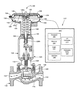
[0017] Referring now to FIG.2, for the sake of description, the field
device 71 from
FIG.1 is shown as a process control device 100 constructed in accordance with
the
6
CA 02920254 2016-02-02
WO 2015/020986 PCT/US2014/049665
present disclosure. In this example, the process control device 100 is a
control valve
assembly that includes a control valve 102, an actuator 104, and a digital
valve
controller 105 communicatively coupled to the control valve 102, and the
actuator
104. As shown in FIG. 2, the digital valve controller 105 is physically
coupled (e.g.,
mounted) to the control valve 102 and the actuator 104, but it need not be
(e.g., it
can be remotely located from the control valve 102 and the actuator 104). In
other
examples, the process control device 100 can be a different type of process
control
device and/or can include different and/or additional components.
[0018] With reference to FIG. 3, further details of the control valve 102,
the
actuator 104, and the digital valve controller 105 will now be described. The
control
valve 102 is a sliding stem type control valve (e.g., a Fisher ED valve) that
includes
a globe-style valve body 106 and a control element 108 disposed for
displacement in
the valve body 106 for controlling the flow of fluid therethrough. The fluid
may be a
gas (e.g., air, natural gas) or a liquid (e.g., water, liquefied natural gas).
The valve
body 106 defines an inlet 110, an outlet 112, and a fluid flow path 114
extending
between the inlet 110 and the outlet 112. The control element 108 includes a
valve
plug 116 connected to a valve stem 118. The valve stem 118 extends out of the
valve body 108 through a bonnet 120 for being coupled to the actuator 104 such
that
the actuator 104 can adjust the position of the control element 108 and, more
particularly, the position of the valve plug 116 relative to the flow path 114
to adjust
the flow of fluid through the control valve 102.
[0019] In other examples, the control valve 102 can be a different type of
control
valve, such as, for example, a rotary control valve (e.g., a Fisher VeeBaIITM
V150
valve, a Fisher VeeBaIITM V300 valve, etc.), a throttle valve, an isolation
valve, or
other control valve. Moreover, the components of the control valve 102 (e.g.,
the
valve body 106, the control element 108, and the bonnet 120) can vary from
what is
depicted herein. For example, the inlet 110, the outlet 112, and the fluid
flow path
114 extending therebetween can vary in shape and/or size and yet still perform
the
intended functionality.
[0020] As shown in FIG. 3, the actuator 104 is a pneumatic sliding stem type
actuator (e.g., a Fisher 667 Actuator). The actuator 104 includes an actuator
body
7
CA 02920254 2016-02-02
WO 2015/020986 PCT/US2014/049665
122, an actuator casing 124, and a positioning assembly 126. The actuator body
122 is a generally hollow construct providing guidance, support, and
protection to at
least a portion of the positioning assembly 126, as shown. The actuator casing
124
includes upper and lower diaphragm casing components 128, 130 fastened
together
with a plurality of fasteners 134 to define an internal actuator cavity 132.
The
positioning assembly 126 includes a diaphragm assembly 136, an actuator rod
138,
and a biasing device 140. The diaphragm assembly 136 is disposed in the
actuator
cavity 132 and includes a diaphragm 142 and a diaphragm plate 144. The
diaphragm plate 144 is a generally rigid disc-shaped member and the diaphragm
142 includes a conventional membrane-type diaphragm, a central portion of
which is
in engagement with the diaphragm plate 144. The diaphragm 142 also includes a
peripheral portion secured between the upper and lower diaphragm casing
components 128, 130 such that the diaphragm 142 divides the actuator cavity
132
into upper and lower sealed cavity portions 146, 148. The actuator rod 138
includes
a first end 138a fixed to the diaphragm plate 144 and a second end 138b
operably
coupled to the valve stem 118 of the control valve 102 via a coupling yoke or
some
other suitable joint. Finally, the biasing device 140 of the actuator 104
depicted in
FIG. 3 includes a compression coil spring disposed between the diaphragm
assembly 136 and a spring seat 150 carried by the actuator body 122 at a
location
below the diaphragm assembly 136. So configured, the biasing device 140
naturally
biases the diaphragm assembly 136 in an upward direction relative to the
orientation
of the actuator 104 in FIG. 3 and away from the spring seat 150. In another
configuration, a similar actuator could have this motion reversed when the
biasing
device tends to hold the valve closed and the pneumatic signal causes the
diaphragm assembly to move toward opening the valve trim.
[0021] Alternatively, the actuator 104 can be a different type of actuator,
such as,
for example, a rotary actuator, a piston actuator, an on-off actuator, a rack-
and-
pinion style actuator, and/or an electric or hydraulic actuator. The
components of the
actuator 104 can also vary from what is depicted herein. For example, the
actuator
body 122, the actuator casing 124, or the positioning assembly 126 can vary in
size
and/or shape and yet still perform the intended functionality.
8
CA 02920254 2016-02-02
WO 2015/020986
PCT/US2014/049665
[0022] The digital valve controller ("DVC") 105 depicted in FIG. 3 is a
Fisher
FIELDVUETm DVC 6200 Digital Valve Controller. In other examples, the digital
valve
controller 105 can be a Fisher FIELDVUETIvi DVC 6000 Digital Valve Controller
or
another type of Digital Valve Controller (e.g., a Digital Valve Controller
manufactured
by Fisher or by another company). The digital valve controller 105 is, as
noted
above, communicatively coupled to the valve 102 and the actuator 104. Although
not explicitly depicted herein, the digital valve controller 105 can also be
communicatively coupled to the process controller 11 described above.
[0023] The digital valve controller 105 has a module base 200. As shown in
FIG.
5, the digital valve controller 105 includes a processor 202, a memory 204, a
communications interface 208, computing logic 212, a I/P converter 216, and a
pneumatic relay 220 disposed within the module base 200. Though not depicted
herein, these components are arranged in a known manner, but can be arranged
in
any manner. One of ordinary skill in the art will appreciate that the digital
valve
controller 105 can also include additional components, such as, for example,
analog-
digital converters, digital-analog converters, amplifiers, and gauges, which
are not
explicitly depicted herein.
[0024] The processor 202 may be a general processor, a digital signal
processor,
ASIC, field programmable gate array, graphics processing unit, analog circuit,
digital
circuit, or any other known or later developed processor. The processor 202
operates pursuant to instructions in the memory 204. The memory 204 may be a
volatile memory or a non-volatile memory. The memory 204 may include one or
more of a read-only memory (ROM), random-access memory (RAM), a flash
memory, an electronic erasable program read-only memory (EEPROM), or other
type of memory. The memory 204 may include an optical, magnetic (hard drive),
or
any other form of data storage device.
[0025] The communications interface 208, which may be, for example, a HART
interface, a FOUNDATIONTm fieldbus interface, a PROFIBUS interface, or some
other port or interface, is provided to enable or facilitate electronic
communication
between the digital valve controller 105 and the process controller 11 and
between
the digital valve controller 105 and other components of the process control
device
9
CA 02920254 2016-02-02
WO 2015/020986 PCT/US2014/049665
(e.g., the valve 102 and the actuator 104). This electronic communication may
occur
via any known communication protocol, such as, for example, the HART
communication protocol, the FOUNDATIONTm fieldbus communication protocol, the
PROFIBUS communication protocol, or any other suitable communication
protocol.
[0026] The logic 212 includes one or more routines and/or one or more sub-
routines, embodied as computer-readable instructions stored on the memory 204.
The digital valve controller 105, particularly the processor 202 thereof, can
execute
the logic 212 to cause the processor 202 to perform actions related to the
operation
(e.g., control, adjustment), maintenance, diagnosis, and/or troubleshooting of
the
control valve assembly 100 (e.g., the control valve 102, the actuator 104,
and/or the
components thereof), as will be described in greater detail below.
[0027] With the process control device 100 configured as described, the
diaphragm-based actuator 104 serves to position the valve plug 116 of the
control
valve 102 relative to the flow path 114 to satisfy desired process control
parameters
(e.g., a desired set-point pressure). For example, as mentioned, the biasing
device
140 of the actuator 104 naturally biases the diaphragm assembly 136 upward
relative to the orientation of FIG.2, which translates into an upward movement
of the
control element 108 of the control valve 102 toward an open position. In order
to
move the control element 108 down toward a closed position, the process
controller
11 can transmit a drive signal to the processor 202 of the digital valve
controller 105.
The drive signal is a 4-20 mA signal, but, in other examples, can be a 0-5 VDC
signal, digital communications signal, or other type of signal. The I/P
converter 216,
which is fluidly coupled to a supply pressure source (e.g., a pressurized air
source),
can convert the drive signal to a pressure signal using the pressurized fluid
(e.g.,
pressurized air, hydraulic fluid, etc.) from the pressure supply source. The
I/P
converter 216 is configured to send the pressure signal to the pneumatic relay
or
switch 220. The pneumatic relay 220 converts the pressure signal to a
pneumatic
signal, which is, in turn, supplied by the processor 202 to the upper cavity
portion
146 of the actuator cavity 132 to increase the pressure in the upper cavity
portion
146. This increase in pressure is sensed by the diaphragm 142 and ultimately
overcomes the force applied by the biasing device 140, thereby moving the
CA 02920254 2016-02-02
WO 2015/020986 PCT/US2014/049665
diaphragm assembly 136, actuator rod 138, and control element 108 in the
downward direction. When the pneumatic signal supplied to the upper cavity
portion
146 is reduced and/or eliminated, the biasing device 140 can expand and urge
the
diaphragm assembly 136, actuator rod 138, and control element 108 upward
relative
to the orientation of FIG. 3.
[0028] The logic 212 may, when executed, cause the processor 202 to obtain
data
associated with and indicative of the operation of the process control device
100.
The data associated with the process control device 100 generally includes
data
associated with or relevant to the fluid flowing through one or more
components of
the process control device 100, such as, for example, the actuator 104 and/or
the
digital valve controller 105.
[0029] The processor 202 may obtain data indicative of characteristics or
properties of the fluid flowing through the digital valve controller 105 at
one point in
time (e.g., a current time, a previous time). The processor 202 may, for
example,
obtain data indicative of a mass of fluid flowing through the digital valve
controller
105 and/or indicative of a volume of fluid flowing through the digital valve
controller
105 at the one point in time. For example, the data may be or include the
position of
the pneumatic relay 220, data measured or collected by one or more sensors
disposed within the digital valve controller 105, or other data. The data may
be
automatically transmitted to the processor 202 (i.e., automatically obtained
by the
processor 202) and/or obtained in response to a request transmitted by the
processor 202. In any event, based on this data, the processor 202 can
determine
the relevant characteristics or properties of the fluid flowing through the
digital valve
controller 105 at the one point in time, such as, for example, the mass and/or
volume
of fluid flowing through the digital valve controller 105 at the one point in
time.
[0030] Alternatively or additionally, the processor 202 may obtain data
indicative
of the fluid quality of the fluid flowing through the actuator 104 and/or the
digital valve
controller 105 at one point in time. The data indicative of the fluid quality
may, for
example, include (i) data indicative of the pollutant content (e.g., Ozone,
SON, NOR,
H2S, or other pollutant) of the fluid due to, for example, the environment or
proximity
of the process control device 100 to an electric motor, (ii) data indicative
of the
11
CA 02920254 2016-02-02
WO 2015/020986
PCT/US2014/049665
particulate content in the fluid, (iii) data indicative of the moisture
content in the fluid,
(iv) other data, or combinations thereof.
[0031] The data
indicative of the fluid quality is received from a user (e.g., a user
of the process control device 100). The user may provide the fluid quality
data
directly via the digital valve controller 105 or via the process controller 11
or a user
device in communication with the digital valve controller 105. The fluid
quality data
may be collected or measured by one or more sensors, such as a pollutant
sensor
configured to detect the pollutant content of the fluid, a particulate sensor
configured
to detect or sense particulates (e.g., dust) in the fluid, a moisture sensor
configured
to detect or sense a level or amount of moisture present in the fluid, one or
more
sensors, or combinations thereof, arranged or disposed within or near the
process
control system 10 (e.g., the process control device 100). As an example, the
user
may enter the data indicative of the fluid quality, measured by the one or
more
sensors, via one of the workstations 13, and, in turn, the controller 11 may
transmit
the data to the processor 202. In other examples, the processor 202 may obtain
some or all of this data directly from the one or more sensors, the actuator
104, the
digital valve controller 105, some other component, or combinations thereof.
[0032] In
addition to obtaining data measured at one-point in time, the logic 212
may, when executed, cause the processor 202 to gather or collect data over a
period
of time (e.g., one week, one month, etc.). This generally involves obtaining
the data
associated with the process control device 100 measured or collected, as
described
above, at two or more different points in time as described above. The
obtained data
may be measured at pre-determined intervals (e.g., every 5 seconds), such that
the
two or more different points in time are separated by the pre-determined
intervals.
Once obtained, the data may be stored in the memory 204 or in another memory.
[0033] In turn, the processor 202 may aggregate, accumulate, or sum some or
all
of the obtained data. In some embodiments, the processor 202 may aggregate
only
the mass or volume data. In other embodiments, the processor 202 may aggregate
the mass data, the volume data, and the fluid quality data. The data may be
summed by or using a summation algorithm, such as, for example a Kahan
algorithm, a Bresenham algorithm, a pairwise algorithm, a Fast Fourier
Transform
12
CA 02920254 2016-02-02
WO 2015/020986 PCT/US2014/049665
algorithm, or the like. For example, the processor 202 may obtain, from the
pneumatic relay 220, data indicative of the measured mass of the fluid flowing
through the digital valve controller 105 at three different points in time,
determine the
mass flowing through the digital valve controller 105 at the three different
points in
time, and, in turn, utilize the summation algorithm to total or sum the mass
data from
the three different points in time and produce the total mass of fluid
consumed over
the three points in time. The data may be aggregated in response to (i.e.,
immediately following) obtaining the data or at a later time. The aggregated
data
may be stored in the memory 204 or in another memory.
[0034] The accumulation of the data may, in turn, produce or yield the total
mass
and/or volume of fluid that has/have passed through the digital valve
controller 105
over the period of time, the total amount or level of pollutants and/or
particulates (in
the fluid) that have passed through the actuator 104 and/or the digital valve
controller
105 over the period of time, the total amount or level of moisture present in
the fluid
that has passed through the actuator 104 and/or the digital valve controller
105 over
the period of time, or combinations thereof. The accumulation may also yield
or
identify patterns in the data, such as, for example, increases or decreases in
the
volume of fluid flowing through the digital valve controller 105 (this might,
for
example, be due to leaks in the process control device 100), as will be
described in
greater detail below
[0035] One or more diagnostic and/or prognostic techniques may be performed
based on or using the obtained and/or aggregated data. The diagnostic and/or
prognostic techniques are generally performed in connection with one or more
components of the process control device 100 that are directly exposed to or
otherwise affected by fluid flowing through the process control device 100
and, thus,
susceptible to the damage described above. In other words, the diagnostic
and/or
prognostic techniques focus on one or more components of the process control
device 100 that are directly exposed to or otherwise affected by fluid (and
pollutants,
particulates, and moisture therein) flowing through the process control device
100,
and, as such, are susceptible to the types of damage noted above. Such
components may, for example, include the diaphragm 142 of the actuator 104,
the
13
CA 02920254 2016-02-02
WO 2015/020986 PCT/US2014/049665
I/P converter 216 of the digital valve controller 105, the pneumatic relay 220
of the
digital valve controller 105, one or more sensors or transducers, other
components,
or combinations thereof.
[0036] The techniques may, for example, include monitoring total flow,
particulate,
pollutant, and/or moisture values (e.g., levels or amounts) over time. For
example,
the total mass of fluid flowing through the digital valve controller 105 may
be
monitored. As another example, the total amount of particulates passing
through the
pneumatic relay 220 of the digital valve controller 105 over a period of time
may be
monitored. The diagnostic techniques may, as another example, include
analyzing
trends or patterns in flow, particulate, pollutant, and/or moisture values.
Changes in
the mass and/or volume of the fluid flow through the respective components
may, in
some cases, be indicative of problems or issues in the process control device
100.
For example, dramatic increases in the mass and/or volume of the fluid flow
through
the digital valve controller 105 may be indicative of a leak in the process
control
device 100. Other diagnostic techniques may also or alternatively be
performed.
Any number of statistical analyses may be performed on or using the total
data. For
example, the mean level of particulates may be calculated over a period of
time. In
other examples, the median, standard deviation, root mean square, or the like
may
be calculated or determined using the total data. Other statistical
techniques, such
as, for example, multivariate statistical techniques, may also be performed on
or
using the total data.
[0037] The techniques may, for example, include assessing a state of one or
more
components (e.g., the diaphragm 142). The state may be a current state of the
one
or more components, such as the current health, integrity, and/or
effectiveness of the
one or more components. Alternatively or additionally, the state may be a
future
state of the one or more components, such as an estimated or predicted health,
integrity, and/or effectiveness of the one or more components. For example,
the
estimated remaining lifespan of the diaphragm 142 may be assessed. In general,
when higher levels of pollutants, particulates, and/or moisture have passed
through
one of the components, the more likely it will be that the respective
component has
suffered damage and is, as a result, not as healthy and/or will not function
effectively
14
CA 02920254 2016-02-02
WO 2015/020986 PCT/US2014/049665
in the future. Conversely, when lower levels of pollutants, particulates,
and/or
moisture have passed through one of the components, the more likely it will be
that
the respective component is healthy and is, as a result, functioning
effectively and/or
will function effectively in the future.
[0038] To assess the state of the one or more components, the mass and/or
volume data and/or the fluid quality data may be compared with other data
and/or a
quality factor or threshold. The other data may, for example, include
empirical data
and/or expected data (e.g., expected values). The empirical data may be or
include
previous mass data, volume data, and/or fluid quality data (e.g., particulate
data,
pollutant data) associated with one or more components of the process control
device 100 or another process control device. Mass, volume, and/or fluid
quality
data that deviate from the previous data may indicate that one or more of the
components are not functioning effectively and/or being exposed to different
levels of
fluid, particulates, pollutants, and/or moisture than before, which may bear
on the
health and/or effectiveness of the one or more components. The expected data
may
be or include average or expected mass data, volume data, and/or fluid quality
data,
such as, for example, mass data, volume data, and/or fluid quality data
typically
expected in connection with the process control device 100. Mass, volume,
and/or
fluid quality data that deviate from the expected data may indicate that one
or more
of the components are being exposed to abnormal levels of fluid, particulates,
pollutants, and/or moisture, and, thus, are not currently in good health
and/or are not
likely to effectively function much longer. The factor or threshold may, for
example,
be a maximum threshold (e.g., a maximum particulate threshold, a maximum
moisture content threshold, a maximum pollutant content threshold, etc.) that
the
aggregated data is not to exceed. When, for example, the total particulate
data
indicates that the diaphragm 142 is being exposed to an amount of particulates
in
excess of the maximum particulate threshold, it can be determined that the one
or
more components may need to be soon replaced.
[0039] The state of the one or more components may be assessed in terms of a
number (e.g., a number between 0 and 10), a grade (e.g., an A), a percentage
(e.g.,
50% healthy/effective), or some other scale. In one example, the state may be
CA 02920254 2016-02-02
WO 2015/020986 PCT/US2014/049665
assessed in terms of a number between 0 and 10, with 0 meaning that the
component is no longer healthy / effective and 10 meaning that the component
is
perfectly healthy / effective.
[0040] In some embodiments, the above-described diagnostic and/or prognostic
techniques may be performed by the processor 202. In other embodiments, the
process controller 11 or some other component of the process control system
10,
rather than the processor 202, may perform the techniques. In yet another
embodiment, the processor 202 may provide the analyzed data and provide the
capability to perform the diagnostic and/or prognostic techniques, but the
techniques
are actually performed by one or more users of the process control system 10
(with
or without the help of the processor 202).
[0041] By monitoring data and/or analyzing changes thereto as described
herein,
performance issues (e.g., leaks) and/or abnormalities in the process control
device
100 can be quickly identified or predicted and remedied. By assessing the
state of
one or more components as described herein, faulty or otherwise non-effective
components can be identified and removed or repaired and the future
effectiveness
and/or health of components can be estimated, thereby improving the
performance
of the process control device 100 and, more generally, the process control
system
10.
[0042] FIG. 4 depicts an exemplary method or process for providing diagnostic
and/or prognostic techniques or capabilities in connection with the process
control
system 10. Although the method or process is described below as being
performed
by the digital valve controller 105 of the process control device 100, the
method or
process may, alternatively, be partially or wholly performed by the process
controller
11, another component or application of the process control system 10, some
other
component or application, or combinations thereof. The method or process is
performed in the order shown and described herein, but may be implemented in
or
according to any number of different orders. In other embodiments, the method
or
process may include additional, fewer, or different acts. For example, the act
of
obtaining the first data (block 300), the act of obtaining the second data
(block 304),
and the act of aggregating or summing the first data and the second data
(block 308)
16
CA 02920254 2016-02-02
WO 2015/020986
PCT/US2014/049665
may be repeated any number of times. As another example, third, fourth, etc.
data
may be obtained and aggregated or summed with any of the other data.
[0043] The method first includes obtaining first data associated with a
fluid flow
through the actuator 104 or the digital valve controller 105 at a first point
in time
(block 300). In some embodiments, obtaining the first data may include
measuring
or collecting data indicative of a mass or volume through the actuator 104 or
the
digital valve controller 105, particularly the pneumatic relay 220 of the
digital valve
controller 105, at the first point in time.
[0044] The method then includes obtaining second data associated with the
fluid
flow through the actuator 104 or the digital valve controller 105 at a second
point in
time (block 304). In some embodiments, obtaining the second data may include
measuring or collecting data indicative of a mass or volume through the
actuator 104
or the digital valve controller 105, particularly the pneumatic relay 220 of
the digital
valve controller 105, at the second point in time. The second point in time is
different
from the first point in time. Any interval (e.g., 1 second, 30 seconds, etc.)
may
separate the first point in time from the second point in time.
[0045] The method further includes aggregating or summing the first data and
the
second data (block 308). The aggregating or summing may be accomplished with
or
using a summation algorithm such as, for example a Kahan algorithm, a
Bresenham
algorithm, a pairwise algorithm, a Fast Fourier Transform algorithm, or the
like.
[0046] In some embodiments, the method further includes obtaining fluid
quality
data (e.g., particulate data, pollutant data, moisture content data)
associated with the
fluid flowing through the actuator 104 or the digital valve controller 105.
The fluid
quality data may be obtained (e.g., received) from a user associated with the
process control device 100. The user may provide the fluid quality data
locally (e.g.,
via the digital valve controller 105) or remotely (e.g., via a user device or
workstation
in communication with the digital valve controller 105). The air quality data
may be
measured or collected by one or more sensors (e.g., one or more sensors
disposed
within or coupled to the process control device 100) at one point in time or
at a
plurality of different points in time by one or more . In some embodiments,
the air
quality data may be aggregated or summed over a period of time as well. For
17
CA 02920254 2016-02-02
WO 2015/020986 PCT/US2014/049665
example, the particulate data over a period of time may be aggregated, such
that the
total level of particulates in the fluid flowing through the actuator 104 or
the digital
valve controller 105 can be determined.
[0047] In turn, the method includes performing one or more diagnostic
and/or
prognostic techniques using or based on the aggregated data and/or the fluid
quality
data (which may, in some embodiments, be aggregated as well) (block 312). The
diagnostic and/or prognostic techniques are generally performed in connection
with
one or more components of the process control device 100 that are directly
exposed
to or otherwise affected by fluid flowing through the process control device 1
00 and,
thus, susceptible to damage from high masses or volumes of fluid, as well as
pollutant contents, particulate contents, and moisture contents in fluid
flowing
through the device 100. The one or more components may, for example, include
the
diaphragm 142 of the actuator 104, the I/P converter of the digital valve
controller
105, the pneumatic relay of the digital valve controller 105, one or more of
the
sensors 160, 1 64, 166, 168, 172, 1 76, other components, or combinations
thereof.
The diagnostic and/or prognostic techniques include, for example, monitoring
the
aggregated mass and/or volume data (i.e., monitoring the mass and/or volume of
fluid flowing through the actuator 104 or the digital valve controller 105),
monitoring
the fluid quality data (i.e., monitoring the particulates, pollutant content,
and/or
moisture content), analyzing changes or trends in the mass data, the volume
data,
and/or the fluid quality data, and/or assessing a state of one or more of the
components of the process control device 100.
[0048] Based on the foregoing description, it should be appreciated that
the
devices and methods described herein provide diagnostic and/or prognostic
capabilities in connection with one or more components of a process control
device
that are directly exposed to or otherwise affected by fluid flow through the
process
control device. By providing these capabilities, performance issues, leaks,
and/or
other abnormalities in the process control device can be quickly identified
and
remedied, faulty or otherwise non-effective components can be quickly and
easily
identified and replaced, and the future performance of components can be
estimated, thereby improving the performance of the process control system.
18