Note: Descriptions are shown in the official language in which they were submitted.
CA 02920640 2016-02-05
WO 2015/020593 1 PCT/SE2014/050870
CURVE CUTTING WITH A CIRCULAR SAW BLADE
TECNICAL FIELD
The invention relates to a method and a calculation unit. More specifically,
the invention
relates to curve sawing of a block utilising at least one circular saw blade.
BACKGROUND
A common way to decompose logs into boards and planks is that in a first stage
in a so-
called stock-taking saw, cut a rectangular block by cutting off the sides,
called back sides
of the log. The block that remains to divide in a second step in a second-
coming so-called
division saw has a rectangular cross section, but is usually more or less
curved in the longi-
tudinal direction, depending on the log curve. Curve sawing is therefore a
usual manner by
sawing recut to decompose the curved block and thus gain advantages as to
quality and
increased yield, as a result of following the grain of the wood to a greater
extent compared
to straight sawing. It may be added that curve sawed boards later straightens
out when
drying.
Curve sawing comprises feeding the curved block past the division saw in a
curved path
that follows the log's curvature. In some cases, a different curve radii when
curve sawing
along a log. This is due to a rootstock often is crooked in the root end, but
may be straight-
ened in the top end. The division saw may be a single circular saw blade
(single blade) or
double circular saw blades (double blades or twin blades).
When sawing recut with double blades, or twin blades, these often are
conflicting and dis-
placed in the feed direction to permit vertical overlap between the circular
saws and a cer-
tain safety margin to prevent the saw blades from coming into contact with
each other. In
some cases the overlying and the underlying saw blade may be parallel to each
other in a
vertical plane, i.e. lack displacement in the feeding direction in relation to
each other. In
such case, the rotation of the saw blades may be synchronised with each other
so that the
saw teeth on each respective the saw blade engage in the gap between the
serrations on
the opposite saw blade, much like the teethes of a pair of inter acting gears,
but without
touching each other.
A problem occurring at such tight curve sawing is that the saw cuts into the
log becomes
oblique and curved due to undesirable geometry. The magnitude of this so-
called decom-
position error may be 0.2-0.6 mm for the relatively large radius curves that
are used today,
approximately 40-60 meters. For double blades the situation becomes even worse
by saw
CA 02920640 2016-02-05
WO 2015/020593 2 PCT/SE2014/050870
cuts are broadened and rear-sawing is done. Rear-sawing means that the blade
of the cir-
cular saw blade's rear part (in the log feed direction) will engage as a
result of unwanted
side forces that push on the blade, resulting in a wider kerf, or saw cut, in
the block than
otherwise. This increases chip loss, resulting in a reduced yield.
Furthermore, due to the undesirable side forces that occur on the saw blade,
it must be
dimensioned to withstand this stress laterally, i.e. to be thicker than
otherwise would be
necessary. This however increases kerf loss further. In addition, there is
also an increased
risk of blade deformation or breakage and /or that the saw blade must be
replaced more
frequently than otherwise which can be costly, not least as the production has
to be
stopped when the saw is at a standstill due to maintenance.
It may also emerge an increased need to insert a wiper slot in the saw blade,
which gener-
ates further sawdust and thus lowers the yield further.
A further problem with curve sawing is that the timber often has a stronger
curvature than
the minimum bending radius possible to comply with a circular saw, resulting
in that the
grain cannot be followed. Another problem is that the wood may be bent in
different direc-
tions. In such case, it may not be possible to curve saw the wood so that the
grain fol-
lowed.
It may be concluded that there is a need for improvement to increase yield and
reduce kerf
loss associated with curve sawing of timber, as well as to increase the
quality of sawn tim-
ber, especially as economical margins may be strained in the sawmill industry.
SUMMARY
It is therefore an object of this invention to avoid at least some of the
above listed disad-
vantages and allow an improved procedure for curve sawing of wood.
According to a first aspect of the invention, this objective is achieved by a
method for curve
sawing of a block in a cutting direction with at least one first circular saw
blade. The
method comprises determining the radius of the curve sawing, by measuring the
curvature
of the block in the direction of cutting. The method also comprises
calculating a vertical
inclination angle of the first circular saw blade in a vertical plane relative
to the direction of
cutting in the block, based on the determined radius of the curve sawing.
Furthermore, the
method also comprises inclining or scewing the first circular saw blade with
the calculated
vertical inclination angle. The method also comprises sawing of the block in
the direction of
CA 02920640 2016-02-05
WO 2015/020593 3 PCT/SE2014/050870
cutting of the inclined first circular saw blade along the determined radius
of the curve saw-
ing.
According to a second aspect of the invention, this objective is achieved by a
calculating
unit for enabling the inclination of at least one first circular saw blade
when curve sawing a
block in a cutting direction. The calculation unit comprises a receiver
configured to receive
a measurement signal from a measurement unit, relating to the block curvature
in the di-
rection of cutting. Further, the calculating unit also comprises a processor,
configured to
determine a radius of the curve sawing, based on the measurement of the
curvature of the
block in the cutting direction, and to calculate a vertical inclination angle
of the first circular
saw blade in a vertical plane relative to the cutting direction in the block,
based on the de-
termined radius of the curve sawing. The calculation unit also comprises a
transmitter con-
figured to transmit a control signal to a control unit, for inclining the
first circular saw blade
with the calculated vertical inclination angle.
By inclining, tilting or skewing the saw blade in the vertical plane when
cutting with single
blade, inclined saw-track is avoided. By correspondingly inclining the saw
blades against
each other when cutting with dual blades, so that both blades are tilted
toward each other,
it is avoided that the saw cuts becomes inclined both at the top and the
bottom of the saw-
track, or kerf. This increases the yield as crude measurements may be reduced
when the
cut boards become more rectangular than they otherwise would be. Thereby, the
radius of
curvature may be reduced, which further increases the yield.
Furthermore, according to some embodiments when cutting with dual blades, the
blade
shafts when cutting with double blades may be angled toward each other in a
horizontal
plane so that the intersection of the extensions of the respective blade
shafts is located in
the centre of curvature of the block. Thereby, back sawing and the broadening
of the saw
track created by back sawing is eliminated, or at least reduced, resulting in
a higher yield
and decreased logging waste.
Other advantages and additional novel features will become apparent from the
following
detailed description of the invention.
LIST OF FIGURES
The invention will now be described in further detail with reference to the
accompanying
figures, which illustrate embodiments of the invention:
CA 02920640 2016-02-05
WO 2015/020593 4 PCT/SE2014/050870
Figure 1A is a schematic illustration showing curve sawing with a single
blade saw
according to an embodiment of the invention.
Figure 1B is a schematic illustration showing curve sawing with a double
blade saw
according to an embodiment of the invention.
Figure 2A is a schematic illustration showing curve sawing with a single
blade saw in a
side perspective, according to an embodiment of the invention.
Figure 2B is a schematic illustration showing curve sawing with a double
blade saw in
a side perspective, according to an embodiment of the invention.
Figure 3A is a schematic illustration showing curve sawing with a single
blade saw
0 according to an embodiment of the invention.
Figure 3B is a schematic illustration showing curve sawing with a double
blade saw
according to an embodiment of the invention.
Figure 4 is a schematic illustration showing curve sawing with a double
blade saw
according to an embodiment of the invention as seen from above.
Figure 5 is a flow diagram illustrating an embodiment of a method for curve
sawing.
Figure 6A is a schematic illustration showing curve sawing with a single
blade saw
according to an embodiment of the invention.
Figure 6B is a schematic illustration showing curve sawing with a double
blade saw
according to an embodiment of the invention.
Figure 7 is an illustration of a calculating unit according to an
embodiment of the in-
vention.
DETAILED DESCRIPTION
The invention is defined as a method and a calculation unit, which may be
realised in any
of the below described embodiments. This invention may be implemented in many
different
forms and should not be seen as limited by the herein described embodiments.
These de-
scribed embodiments are rather intended to illustrate various aspects of the
invention.
Further aspects and features of the invention may become apparent from the
following
detailed description, taken in conjunction with the accompanying drawings.
Figures are
however rather to be consider as examples of various embodiments of the
invention and
should not be viewed as limiting the invention, which is limited only by the
accompanying
patent claims. Furthermore, the figures are not necessarily drawn to scale and
are, unless
otherwise stated, intended to conceptually illustrate various aspects of the
invention.
Figure 1A shows curve sawing with single blade according to an embodiment of
the inven-
tion. A block 100 of a certain curvature with a radius of curvature R is fed
passing a first
CA 02920640 2016-02-05
WO 2015/020593 5 PCT/SE2014/050870
circular saw blade 110 in a curved path, wherein the first circular saw blade
110 herein will
cut up a kerf, or saw cut (dashed line in the Figure) in a cutting direction S
through the
block 100. This first circular saw blade 110 may also be denominated single
blade and is in
the illustrated example performing as a division saw, as referenced in the
background sec-
tion.
In some embodiments, such division saw may also comprise a plurality of single
blades
which operate in parallel with each other to thereby partition the block 100
in boards and
planks in one single fed of the block 100 through the division saw.
Figure 1B illustrates curve sawing with double blade according to an
embodiment of the
invention. The block 100, which has a certain curvature with a radius of
curvature R, is fed
in a curved path passing the first circular saw blade 110 and a second
circular saw blade
120, which thereby are cutting a kerf, or saw cut (dashed line) in the block
100, in the cut-
ting direction S. This first circular saw blade 110, together with the second
circular saw
blade 120, which also may be termed double blade or dual blade, are in the
illustrated ex-
ample, performing as the division saw referenced in the background section.
In some embodiments, such division saw may also comprise a plurality of double
blades
which may operate in parallel with each other to thereby partition the block
100 in boards
and planks in one single fed of the block 100 through the division saw.
Figure 2A shows curve sawing in a single blade embodiment of the invention,
illustrated in
a side view. The block 100, which has a certain curvature with a radius of
curvature R is
fed in a curved path passing the first circular saw blade 110, whereby the
first circular saw
blade 110 herein will sawing up a kerf, or saw cut, in the cutting direction S
through the
block 100. The block 100 may for example be fed to the first circular saw
blade 110 on a
treadmill according to some embodiments. The first circular saw blade 110,
which has a
diameter d, rotates about a shaft 130 in a horizontal plane H. The rotation of
the first circu-
lar blade 110 may be made either counter-clockwise, which is most common, or
clockwise.
Regardless of the direction of rotation of the circular saw blade 110, the
desired sawing
zone is situated in front of a vertical plane V passing through the first saw
blade shaft 130,
while an undesired back sawing zone is situated behind this vertical plane V,
relative to the
direction of cutting S.
Figure 2B shows curve sawing with double blade of embodiment of the invention,
viewed
in side view. The block 100, which has a certain curvature with a radius of
curvature R, is
CA 02920640 2016-02-05
WO 2015/020593 6 PCT/SE2014/050870
fed into a curved path passing the first circular saw blade 110 and the second
circular saw
blade 120 in a curved path, wherein the first circular saw blade 110 along
with the other
circular saw blade 120 herein will cut up a joint kerf in the direction of
cutting S through the
block 100. The block 100 may for example be fed to the first circular saw
blade 110 and
second circular saw blade 120 on a treadmill with a saw base 200 in which the
block 100 is
situated, in some embodiments. The first circular saw blade 110 rotates about
a shaft 130
in the horizontal plane H. The second circular saw blade 120 rotates about a
shaft 140 in
the horizontal plane H.
The rotation of the first and second circular saw blades 110, 120 may be made
either coun-
terclockwise, which is most common, or clockwise in different embodiments.
Regardless of
the direction of rotation of the cutting circular saw blades 110, 120, the
desired sawing
zone is situated forward of a vertical plane V passing through the respective
shafts 130,
140 of the respective cutting circular saw blades 110, 120; while an undesired
back sawing
zone is located behind the vertical plane V, in relation to the direction of
cutting S.
Figure 3A is a schematic illustration showing curve sawing according to a
single blade
embodiment of the invention, wherein the first circular saw blade 110 is
inclined at a verti-
cal angle of inclination 13 in relation to the vertical plane V.
By inclining the circular saw blade 110 in the vertical plane V, with the
vertical angle of in-
clination [3 slanted kerfs may be avoided when curve sawing the block 100. The
size of
such vertical inclination angle [3 may for example be determined as a function
of the curva-
ture radius R in some embodiments.
In this way, when the slanted kerfs are eliminated or at least reduced, the
yield is increased
as crude measures may be reduced. This in turn may also enable the curve
radius R to be
reduced, which further increases the yield and quality of the sawn timber when
the curve
sawing better follows the log curvature and thus the fibre direction of the
wood. The wood
has better strength properties in the fibre direction than in other
directions. Back sawing
may further be avoided, which reduces the width of the kerf and thereby also
increases the
yield further. Further reduced lateral load on the circular saw blade 110 thus
enable further
reduction of the curve radius R and in some embodiments also the blade
thickness, further
increasing the yield and quality of the sawn timber. By controlling the
circular saw blade
110 according to an algorithm, or by a look-up table, a correction of the kerf
created in the
block 100 from curve sawing by the circular saw blade 110 is accomplished.
CA 02920640 2016-02-05
WO 2015/020593 7 PCT/SE2014/050870
The vertical angle of inclination [3 may e.g. be set to 0.23 degrees in tight
curves with a
radius of curvature R of 50 meters. This represents a slope of 0.6 mm over a
height of 150
mm. This is merely mentioned as an illustrative example of possible angle of
inclination [3.
A typical size of the vertical angle of inclination [3 may in practice be less
than 1 degree.
Further, the vertical angle of inclination [3 may depend not only by the
curvature radius R,
but also by further parameters according to some embodiments, such as the
block height,
blade diameter d and/ or by a vertical distance from the centre of the circle
saw blade to
the saw base 200 on which the block 100 is situated, according to some
embodiments.
Further, the vertical angle of inclination [3 may be calculated based on the
following algo-
rithm in some embodiments:
[3 = arctan (Xaverage X0)/((d/ 2) - u),
wherein:
Xaverage = (Xstart Xend)/2;
Xtop = R(1-cos atop)/cos atop;
)(end = R(1-cos aend)/cos aend;
Xstart = R(1-cos astart)/cos astart;
atop = arctan (-e/2)/R;
aend = arctan (d/2 sin yend - (e/2))/R;
astart = arctan (d/2 sin Ystart - (e/2))/R;
Ystart = arccos (u/(d/2));
Yend = -Ystart;
Ytop = 0;
u = the vertical distance from the centre of the circular saw blade to the saw
base
200 on which the block 100 is placed during the sawing; and
d = diameter of the circular saw blade.
Figure 3B is a schematic illustration depicting curve sawing with double blade
according to
an embodiment of the invention, wherein the second circular saw blade 120 is
inclined with
a vertical angle of inclination [3, and the first circular saw blade 110 is
inclined at a vertical
angle of inclination -p, relative to the vertical plane V. Hereby, by allowing
the circular saw
blades 110, 120 to lean against each other, such that tilting of both upper
and lower part of
the kerf may be avoided during curve sawing of the block 100. The magnitude of
this verti-
cal angle of inclination p and -r3 respectively, may for example be determined
as a function
of the radius of curvature R in some embodiments.
CA 02920640 2016-02-05
WO 2015/020593 8 PCT/SE2014/050870
In this way, as the saw cut slope, or tilting kerf as it also may be referred
to as, may be
eliminated or at least reduced, the yield may be increased as crude measures
may be re-
duced. This in turn may also lead to that the curve radius R may be reduced,
which further
may increase the yield and quality of the sawn timber as the made curve sawing
better
follows the log curvature and thus the fibre direction of the wood. The timber
has better
strength properties in the fibre direction than in other directions. Further,
back sawing may
be avoided, which reduces the width of the saw cut and thereby further
increase the yield.
In addition, the lateral load on the circular saw blades 110, 120 is reduced,
which makes it
possible to further reduce the curve radius R and in some embodiments even saw
blade
thickness, further increasing the yield and quality of the sawn timber. By
controlling the
circular saw blades 110, 120 according to an algorithm, or by a look-up table,
a correction
of the saw cut when curve sawing with the circular saw blades 110, 120 through
the block
100 may be achieved.
The vertical angle of inclination [3 and - [3 respectively, may e.g. be set to
0.23/ -0.23 de-
grees in tight curves with a radius of curvature R of 50 meters. This
represents a slope of
0.6 mm over a height of 150 mm. This is merely mentioned as an illustrative
example of
possible angle of inclination [3. A typical size of the vertical angle of
inclination w - [3 may in
practice be less than 1 degree.
Further, the vertical angle of inclination [3/ 13 may depend not only on the
curvature radius
R, but also on further parameters according to some embodiments, such as on
the block
height, blade diameter d and/ or by a vertical distance from the centre of the
circular saw
blade to the saw base 200 on which the block 100 is placed, according to some
embodi-
ments.
Further, the vertical angle of inclination [3/ 13 may be calculated based on
the following al-
gorithm in some embodiments:
[3. = arctan (Xaverage Xt0p)/((d/2) t-I);
- [3 = - arctan (Xaverage Xt0p)/((d/2) - u),
wherein:
Xaverage = (Xstart Xend)/2
Xtop = R(1-cos atop)/cos atop;
)(end = R(1-cos aend)/cos aend;
Xstart = R(1-cos astart)/aos astart;
CA 02920640 2016-02-05
WO 2015/020593 9 PCT/SE2014/050870
atop = arctan (-e/2)/R;
aend = arctan (d/2 sin vend - (e/2))/R;
astart = arctan (d/2 sin ystart - (e/2))/R;
Ystad = arccos (u/(d/2));
Yend = -Ystart;
Ytop = 0;
u = the vertical distance between the centre of the circular saw blade and the
saw
base 200 on which the block 100 is placed during the sawing; and
d = diameter of the circular saw blade.
Figure 4 is a schematic illustration showing the curve sawing with double
blade according
to the embodiment of the invention, seen in a top view.
The blade axes of the first circular saw blade 110 and second circular saw
blade 120 are
here angled toward each other in the horizontal plane H with a horizontal
angle E, for point-
ing to a common centre of curvature. This angling with a respective horizontal
inclination
angle c may in some embodiments be made variable as a function of the position
of the
centre of curvature and thus be a function of the radius of curvature R.
Hereby, the saw cut slope, or tilting kerf, or inclination of the saw cut may
be eliminated or
at least reduced. This increases the yield as crude measurements may be
reduced. This in
turn may also lead to that the curve radius R may be reduced, which further
increases the
yield and quality of the sawn timber when the curve sawing may better follow
the log curva-
ture and thus the fibre direction of the wood. The wood has better strength
properties in the
fibre direction than in other directions. Back sawing may be further avoided,
thus reducing
width of the saw cut and thereby further increase the yield. In addition, the
lateral load on
the circular saw blades 110, 120 is reduced, which makes it possible to
further reduce the
curve radius R and in some embodiments even saw blade thickness, further
increasing the
yield and quality of the sawn timber. By controlling the horizontal angle of
inclination c of
the circular saw blades 110, 120 according to an algorithm, or by a look-up
table, a correc-
tion of the saw cut when curve sawing with the circular saw blades 110, 120
through the
block 100 may be achieved.
The horizontal angle of inclination c of the first circular saw blade 110 and
the second circu-
lar saw blade 120 may in some embodiments be based, in addition to being based
on the
determined radius R of the curve sawing, on a distance e/ 2 in the cutting
direction S be-
CA 02920640 2016-02-05
WO 2015/020593 10 PCT/SE2014/050870
tween the centre of circle saw blade and a centre plane for the radius R of
the curve saw-
ing of the block 100 according to some embodiments.
The horizontal inclination angle c of the first circular saw blade 110 and/ or
the second cir-
cular saw blade 120 may for example be based on the following algorithm
according to
some embodiments:
c = arctan((e/2)/R),
wherein e/2 = a distance in the direction of cutting S between the centre of
the circle saw
blade and a centre plane of the radius R of the curve sawing of the block 100.
Figure 5 is a flow diagram illustrating an embodiment of a curve cutting
methodology. The
flow chart of Figure 5 illustrates a method 500 for curve sawing in a cutting
direction S of a
block 100 with at least one first circular saw blade 110. The block 100 may
comprise a log
of wood on which the sides have been previously cut. The log of wood may
comprise any
arbitrary kind of wood, such as e.g. pine, spruce, oak, beech, birch or
similar. The block
100 has a curvature in the cutting direction S with a radius of curvature R.
This radius of
curvature R may vary along the block length, or be constant in different
embodiments.
To perform curve sawing correctly, the method 500 comprises a number of
actions 501-
508. It should be noted that some of the described actions may be comprised
only in some
alternative embodiments of the invention, such as actions 504-507. Further, it
is noted that
the described actions may be performed in a somewhat different chronological
order than
the order number indicates, and/ or that some of them may be performed in
parallel. The
procedure 500 comprises the following actions:
Action 501
A radius R of the curve sawing is determined by measuring the curvature of the
block 100
in the cutting direction S. The cutting direction S is situated in the
horizontal plane H and is
opposite to the feed direction of the block 100.
This measurement may be performed before the log arrives to the stock-taking
saw, or
while the block 100 is located between the stock-taking saw and dividing saw
according to
various embodiments. Further, measurements of the curvature of the block 100
may be
repeated continuously according to some embodiments, while the block 100 is
processed.
Further, the determined radius R of the curve sawing may vary along the
cutting direction S
of the block 100, e.g., when the block 100 has an S-shape or the like. Thus,
according to
CA 02920640 2016-02-05
WO 2015/020593 11 PCT/SE2014/050870
some embodiments, a plurality of radii R of the block 100 may be determined,
which varies
along the direction of cutting S.
Action 502
A vertical angle of inclination [3 of the first circular saw blade 110 is
calculated in a vertical
plane V in relation to the direction of cutting S in the block 100, based on
the determined
radius R of the curve sawing.
The calculation of the vertical angle of inclination [3 of the first circular
saw blade 110 and /
or second circular saw blade 120 may in some embodiments be based on, in
addition to
the determined radius R of the curve sawing, on the diameter d of the circular
saw blade
and/ or the vertical distance u from the centre of the circular saw blade to a
saw base 200,
on which the block 100 is situated.
According to some embodiments, the calculation of the vertical angle of
inclination [3 of the
first circular saw blade 110 and/ or the second circular saw blade 120 may be
based for
example on the following algorithm:
[3 = arctan (Xaverage Xt0p)/((d/2) - u),
wherein:
Xaverage = (Xstart )(end)/2;
Xtop = R(1-cos atop)/cos atop;
)(end = R(1-cos aend)/cos aend;
Xstart = R(1-cos astart)/cos astart;
atop = arctan (-e/2)/R;
aend = arctan (d/2 sin yend - (e/2))/R;
astart = arctan (d/2 sin Ystart - (e/2))/R;
Ystart = arccos (u/(d/2));
Yend = -Ystart;
Ytop = 0;
U = the vertical distance between the centre of the circular saw blade and the
saw
base 200 on which the block 100 is placed during the sawing; and
d = diameter of the circular saw blade.
Action 503
The first circular saw blade 110 is inclined by the estimated 502 vertical
angle of inclination
R.
CA 02920640 2016-02-05
WO 2015/020593 12 PCT/SE2014/050870
By inclining the first circular saw blade 110 in the vertical plane V with the
vertical angle of
inclination p when cutting with single blade, a sloped kerf may be avoided, or
at least may
problems associated with such sloped kerf be reduced. This increases the yield
as crude
measurements may be reduced when the cut boards become more rectangular than
they
otherwise would be.
Another effect of inclining the circular saw blade 110 with the calculated 502
vertical angle
of inclination p in the vertical plane V is that the curve radius R may be
reduced. Hereby is
it enabled to make curved cuts with a smaller radius of curvature R than
previously possi-
ble because of the resulting slope of the kerf in the prior art. By enabling
curve sawing with
tighter radius R, it is possible to further increase the yield and quality of
the cut boards
when the logs frequently are more curved than the minimum radius of curvature
R that ac-
cording to prior art solutions may be possible to follow during curve sawing.
Action 504
This action may be performed in some alternative embodiments of the method
500,
wherein the curve sawing is performed by the first circular saw blade 110 and
a second
circular saw blade 120, which is positioned offset in the vertical plane V in
relation to the
first circular saw blade 110. The circular saw blades 110, 120 may saw a
single joint saw
cut through the block 100 along the determined 501 radius R of the curve
sawing.
The second circular saw blade 120 may be inclined with the calculated 502
vertical angle
of inclination p in the opposite direction in the vertical plane V in relation
to the first circular
saw blade 110, so that the second circular saw blade 120 is inclined towards
the first circu-
lar saw blade 110 in the vertical plane V. An example of such inclination of
first and second
circular saw blades 110, 120 is illustrated in Figure 3B.
By inclining the circular saw blades 110, 120 in the vertical plane V, with
the vertical angle
of inclination f3, it may be avoided that the kerf is tilted at both the top
and bottom of the
kerf. Thereby slanted kerfs may be avoided or at least may the problems
associated with
such slanted kerfs be reduced. Thus, the yield increased by crude measurements
may be
reduced when they sawed boards become more rectangular than they otherwise
would be.
Action 505
This action may be performed in some alternative embodiments of the method
500, in
which action 504 has been performed.
CA 02920640 2016-02-05
WO 2015/020593 13 PCT/SE2014/050870
A horizontal inclination angle c may be calculated for the first circular saw
blade 110 and
the second circular saw blade 120 in a horizontal plane H in relation to the
direction of cut-
ting S in the block 100, based on the determined radius R of the curve sawing.
The calculation of the horizontal angle of inclination c of the first circular
saw blade 110 and
the second circular saw blade 120 may in some embodiments be based on, in
addition to
the determined radius R of the curve sawing, on a distance e/ 2 in the
direction of cutting S
between the circular saw blade centre and a centre plane of radius R of the
curve sawing
of the block 100.
The horizontal angle of inclination c of the first circular saw blade 110 and/
or the second
circular saw blade 120 may according to some embodiments be based on the
following
algorithm:
c = arctan((e/2)/R),
wherein:
e/2 = a distance in the direction of cutting S between the centre of the
circle saw
blade and a centre plane of the radius R of the curve sawing of the block 100.
Action 506
This action may be performed in some alternative embodiments of the method
500, in
which action 504 and action 505 have been performed.
The first circular saw blade 110 may be inclined by the estimated 505
horizontal angle of
inclination E.
Thereby back sawing may be avoided when sawing with double blades, as the
lateral load
on the circular saw blades 110, 120 decreases. This leads to reduced kerf
width and thus
also increased yield as less wood is lost in sawdust. In addition, by the
decreased lateral
load on the circular saw blades 110, 120, blade thickness of the circular saw
blades 110,
120 may be reduced, further reducing chip wastage and leading to furthermore
increased
yield.
Action 507
This action may be performed in some alternative embodiments of the method
500, in
which action 504, action 505 and action 506 have been performed.
The second circular saw blade 120 may be inclined with the calculated 505
horizontal an-
CA 02920640 2016-02-05
WO 2015/020593 14 PCT/SE2014/050870
gle of inclination c but in the opposite direction in the horizontal plane H
with respect to the
first circular saw blade 110 so that the second circular saw blade 120 is
inclined towards
the first circular saw blade 110 in the horizontal plane H.
Action 508
The block 100 is cut into the direction of cutting S with the inclined 503
first circular saw
blade 110 along the determined 501 radius R of the curve sawing.
According to some embodiments, the method 500 may be performed continuously
during
the sawing of the block 100. Hereupon, the radius of curvature R may be
continuously
measured and remeasured at the block 100 and the vertical inclination angle
f3, respec-
tively, the horizontal angle of inclination c recalculated based on such
continuous meas-
urement. It is thereby enabled sawing along a varying radius R of the curve
sawing of the
block 100, as well as a varying slope in the vertical plane V and possibly the
horizontal
plane H, depending on the varying radius R.
Thereby curved cuts are enabled that better follows the block curvature,
cutting the boards
better following the grain of the wood. This increases the quality of the cut
boards further.
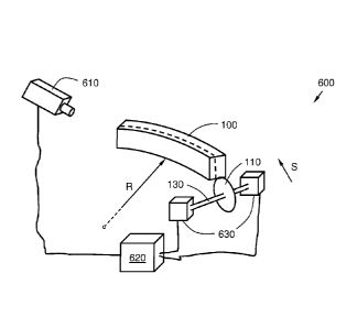
Figure 6A shows a system 600 configured to incline at least one first circular
saw blade
110 during curve sawing in a cutting direction S of a block 100, when curved
cutting is
made with a single blade. As previously mentioned, a plurality of circular saw
blades may
be mounted in parallel in a horizontal plane, for example on the same shaft
130, whereby
the final cutting of a plurality of boards of the block 100 may be made in one
single feed
according to some embodiments.
The system 600 comprises a measuring unit 610, configured to measure the
curvature in
the direction of cutting S of the block 100. This measurement device 610 may
for example
measure the distance to some measurement points on the block 100 by means such
as
light, e.g. laser, or other electromagnetic radiation. Hereupon, laser
triangulation may be
used for performing the measurement in accordance with certain embodiments. In
some
embodiments, the measuring device 610 may comprise e.g. a 3D camera, a Time of
Flight
(TOF) camera, a stereo camera, a light-field camera, or the like. The
measurement device
610 may further for example comprise a 3D log scanner in certain embodiments.
Such 3D
measurement frame may comprise laser light measures of the distance to the
surface of
the block 100 as it passes through the measurement frame. Thereby, the whole
surface of
CA 02920640 2016-02-05
WO 2015/020593 15 PCT/SE2014/050870
the log to be seen and each measuring beam has in turn a plurality of laser
measuring de-
vices.
The measurement unit 610 may for example determine the distance of a
measurement
point on the block 100 by emitting a modulated light wave, detecting the
corresponding
reflected light wave from the measuring point at block 100 and measuring the
reflected light
wave offset relative to the emitted light wave. The distance to the respective
measuring
points may then be calculated as the wavelength of light and the speed is
known parame-
ters.
A Time-of-Flight camera is a camera that takes a sequence of images and
measuring a
distance to an object based on the known speed of light by measuring the time
required for
a light signal between the camera and subject/ object.
The measurement unit 610 may then transmit the measured distances to measuring
points
on the block 100 to a calculation unit 620, which is also comprised in the
system 600. The
calculation unit 620, which will be described in conjunction with the
description of Figure 7,
is configured to perform calculations based on measurements received from the
measure-
ment device 610, which calculations may establish such block curvature radius
R to be
utilised when curve sawing the block 100. Further, the calculation unit 620
may be config-
ured to calculate a vertical angle of inclination [3 of the first circular saw
blade 110 in a ver-
tical plane V in relation to the cutting direction S of the block 100, based
on the determined
radius R of the curve sawing. The calculation unit 620 may comprise for
example a com-
puter or similar device with the required computing capacity.
The measurement unit 610 may also be configured to generate and transmit a
control sig-
nal to a control unit 630, which is also comprised in the system 600. The
control unit 630,
which for example may be situated in at least one end of the first shaft 130
of the first circu-
lar saw blade 110, may cause inclination of the first circular saw blade 110
with the calcu-
lated vertical angle of inclination f3, for example, by inclining the first
circular saw-blade
shaft 130, in either or both of the mounting points of the shaft 130.
The measurement unit 610, the calculation unit 620 and the control unit 630,
which are
comprised in the system 600 may comprise distinct logical entities, or may
alternatively in
some embodiments be housed in the same or partly the same physical device. For
exam-
ple, the calculation unit 620 may be comprised within the measurement device
610 or the
CA 02920640 2016-02-05
WO 2015/020593 16 PCT/SE2014/050870
control unit 630 in some embodiments. Further, the listed devices 610, 620,
630 are ar-
ranged to communicate with each other over a wired or wireless interface.
Such wireless interface may comprise communication via radio waves, for
example, based
on, or inspired by, any of the following technologies: GSM, EDGE, UMTS, CDMA,
CDMA2000, TD-SCDMA, LTE, LTE-Advanced; Wi-Fi, according to one of the IEEE
stan-
dards 802.11 a, b, g and/or n, IP, Bluetooth and/or NFC (Near Field
Communication).
Said wired interface may comprise e.g. a cable connection, an Internet-
connected network
or a communication system comprising one or more communication buses to
interconnect
the enumerated units 610, 620, 630 with each other and alternatively also with
other de-
vices such as a controller and/ or sensor. The communication bus may for
example com-
prise one or more of a cable; a data bus, such as a CAN bus (Controller Area
Network
bus), a MOST bus (Media Oriented Systems Transport), or any other bus
configuration; or
alternatively a wireless connection, based on e.g. any of the above listed
technologies for
wireless communication.
Figure 6B illustrates an embodiment of the system 600, configured for
inclination, or mis-
alignment, of a first circular saw blade 110 and a second circular saw blade
120 when per-
forming curve sawing in a saw direction S of a block 100, i.e., performing
curve sawing with
dual blade. As previously mentioned, a plurality of circular saw blades 110,
120 may be
mounted parallel to the horizontal, for example at the same respective shaft
130, 140,
whereby the simultaneous cutting of a plurality of boards in the block 100 is
made possible
according to some embodiments.
In this illustrative scenario, the curve sawing of the first circular saw
blade 110 and the
second circular saw blade 120, which second circular saw blade 120 is
positioned offset in
the vertical plane V in relation to the first circular saw blade 110 (and in
some alternative
embodiments displaced also in the horizontal plane H), saw a single joint saw
cut through
the block 100 along with the determined radius R of the curve sawing. The
control unit 630
is thereby further configured to incline also the second circular saw blade
120 with the cal-
culated vertical inclination angle in the opposite direction in the vertical
plane V in relation
to the first circular saw blade 110 so that the second circular saw blade 120
is inclined to-
wards the first circular saw blade 110 in the vertical plane V. This feature
has previously
been illustrated in Figure 3B and as further explained in conjunction with the
description of
Figure 3B.
CA 02920640 2016-02-05
WO 2015/020593 17 PCT/SE2014/050870
Further, the calculating unit 620 according to some embodiments may be
configured to
calculate a horizontal angle of inclination c of the first circular saw blade
110 and the sec-
ond circular saw blade 120 in a horizontal plane H in relation to the
direction of cutting S in
the block 100, based on the determined radius R of the curve sawing. Hereupon,
although
the control unit 630 may be configured to incline the first circular saw blade
110 with the
calculated horizontal inclination angle c, and to incline the second circular
saw blade 120
with the calculated horizontal inclination angle c but in the opposite
direction in the horizon-
tal plane H with respect to the first circular saw blade 110, such that the
second circular
saw blade 120 is inclined towards the first circular saw blade 110 in the
horizontal plane H.
This relationship is illustrated in Figure 4 and discussed in detail in the
corresponding text
of the description.
The control unit 630 may, according to some embodiments comprise a plurality
of physical
devices, arranged to operate on the shaft 130 of the first circular saw blade
110, and/ or
the shaft 140 of the second circular saw blade 120, in the horizontal plane
and/ or the verti-
cal plane respectively, such that the desired angular relationship of the
circular saw blades
110, 120 is obtained.
Figure 7 is also illustrating a schematic overview of the system 600,
configured to incline at
least one first circular saw blade 110 when performing curve sawing of a block
100 in a
saw direction S, but with a particular focus on calculating unit 620.
The calculation unit 620 is configured to perform at least some of the
previously-described
actions 501-508, comprised in the description of the method 500 for curve
sawing of a
block 100 in a direction of sawing S with at least one first circular saw
blade 110.
The calculation unit 620 enables inclination or misalignment, i.e. skew or
bias, of at least a
first circular saw blade 110, when performing curve sawing of the block 100 in
the direction
of sawing S. The calculation unit 620 may for example comprise a computer or
the like in
some embodiments. Such computer may be e.g., a desktop computer, a server, a
mobile
computer, a PDA, a tablet, a phone, a netbook or similar.
In order to correctly calculate and thereby enable inclination of the circular
saw blade 110,
or circular saw blades 110, 120, the calculating unit 620 comprise a number of
compo-
nents, which are detailed in the following detailed description. It may be
noted that some of
the described components may be present in some embodiments only. Furthermore,
it is
noted that some additional electronics of the calculation unit 620, not
entirely required in
CA 02920640 2016-02-05
WO 2015/020593 18 PCT/SE2014/050870
order to understand the function of the calculation unit 620 according to the
invention, has
not been depicted in Figure 7, to not impede or unnecessarily complicate the
understand-
ing of the invention.
The calculation unit 620 comprises a receiver 710. The receiver 710 is
configured to re-
ceive a measurement signal from a measurement unit 610, comprising information
related
to the curvature of the block 100 in the cutting direction S.
The receiver 710 is configured to receive the measurement signal from the
measurement
unit 610 over a wired or wireless interface according to different
embodiments.
Furthermore, the calculation unit 620 comprises a processor 720. The processor
720 is
configured to determine a radius R of the curve sawing, based on the received
result of the
measurement of the curvature of the block 100 in the cutting direction S. The
processor
720 is also configured to calculate a vertical inclination angle of the
first circular saw
blade 110 in a vertical plane V, in relation to the cutting direction S in the
block 100, based
on the determined radius R of the curve sawing.
The processor 720 may comprise, for example, one or more Central Processing
Unit(s)
(CPU), microprocessor(s) or other logic designed to interpret and execute
instructions and/
or to read and write data. The processor 720 may handle data for input,
outflow or comput-
ing of data, also comprising data buffering, control and the like.
In some embodiments, the processor 720 may be further configured to calculate
a horizon-
tal inclination angle c of the first circular saw blade 110 and the second
circular saw blade
120, in a horizontal plane H in relation to the cutting direction S in the
block 100, based on
the determined radius R of the curve sawing, in some embodiments.
The calculation unit 620 also comprises a transmitter 730. Transmitter 730 is
configured to
send a control signal to a control unit 630, comprising an instruction for
inclining the first
circular saw blade 110 with the calculated vertical inclination angle 8.
According to certain embodiments the curve sawing may be performed by means of
the
first circular saw blade 110 and a second circular saw blade 120, which is
positioned in
offset in the vertical plane V in relation to the first circular saw blade
110. Said saw blades
110, 120 may create a single joint saw cut through the block 100 along the
determined
radius R of the curve sawing.
CA 02920640 2016-02-05
WO 2015/020593 19 PCT/SE2014/050870
The transmitter 730 may then be further configured to send a control signal to
the control
unit 630, for inclining the second circular saw blade 120 with the calculated
vertical inclina-
tion angle 8, but in the opposite direction in the vertical plane V in
relation to the first circu-
lar saw blade 110 so that the second circular saw blade 120 is inclined toward
the first cir-
cular saw blade 110 in the vertical plane V.
The transmitter 730 may also be configured to send a control signal to the
control unit 630,
for inclining the first circular saw blade 110 with the calculated horizontal
angle of inclina-
tion c, and inclining the second circular saw blade 120 with the calculated
horizontal incli-
nation angle c but in the opposite direction in the horizontal plane H,
relative to the first
circular saw blade 110 so that the second circular saw blade 120 is inclined
towards the
first circular saw blade 110 in the horizontal plane H, which is illustrated
in Figure 4.
The transmitter 730 is configured to transmit the control signal to the
control unit 630 over a
wired or wireless interface, such as e.g. any of the aforementioned wired or
wireless inter-
faces.
Further, the calculation unit 620 may comprise, or be connectable to, a
volatile or non-
volatile data memory 725 i.e., a storage means for data such as e.g., a memory
card, a
flash drive, a USB memory stick, a hard drive or other similar data storage
device. On the
data memory 725 may for example information related to certain curve radii R
be stored in
a look-up table or the like, associated with various respective corresponding
values of the
vertical inclination angle p, and/ or the horizontal inclination angle E.
In some embodiments, the calculation unit 620 may comprise or be connectable
to a moni-
tor (not shown). The monitor may be configured to show and/ or illustrate
information re-
lated to the curve sawing, such as text or image illustrating aspects of the
curve sawing to
a human operator of the saw.
Furthermore some embodiments of the invention may comprise a computer program
for
controlling the curve sawing of the block 100 in the cutting direction S with
at least one first
circular saw blade 110. Such a computer program may be configured to perform
the
method 500, according to at least one of the actions 501-508 when the computer
program
is executed in the processor 720 in the calculation unit 620.
CA 02920640 2016-02-05
WO 2015/020593 20 PCT/SE2014/050870
The actions 501-508 previously described may be implemented by one or more
processors
720 of the calculation unit 620, along with computer program code for
performing any,
some or all of the actions 501-508. Thereby, a computer program comprising
instructions
for performing the actions 501-508, may calculate a vertical inclination angle
[3 of the first
circular saw blade 110 in a vertical plane V in relation to the direction of
cutting S in a block
100 with a particular measured radius R of the curve sawing, thereby enabling
inclination of
the first circular saw blade 110 with the calculated vertical inclination
angle f3, then the
computer program is loaded into the processor 720.