Note: Descriptions are shown in the official language in which they were submitted.
CA 02920662 2016-02-05
WO 2015/021434
PCT/US2014/050426
METHODS AND APPARATUSES FOR SKIN TREATMENT USING NON-THERMAL TISSUE
ABLATION
Background of the Invention
This invention relates to methods, apparatuses, and devices for treating skin
and proximal tissue
layers (e.g., such as fat, muscle, and facial SMAS (superficial muscular
aponeurotic system)), such as
skin tightening, or for treating diseases, disorders, and conditions that
would benefit from tissue area or
volume reduction, skin restoration, skin tightening, skin lifting, or skin
repositioning, or tattoo removal.
Many human health issues arise from the damage or loss of tissue due to
disease, advanced
age, and/or injury. In aesthetic medicine, elimination of excess tissue and/or
skin laxity is an important
concern that affects more than 25% of the U.S. population. Conventional
surgical therapies (e.g., a face
lift, brow lift, or breast lift) can be effective but are often invasive,
inconvenient, and expensive, while
scarring limits the applicability of surgery to certain treatment sites.
Although minimally invasive methods are available, such methods are generally
less effective
than surgical methods. Methods using energy sources (e.g., laser, non-coherent
light, radiofrequency, or
ultrasound) can be effective at improving the architecture and the texture of
the skin but are much less
effective at tightening the skin or reducing skin laxity. Neurotoxins, such as
botulinum toxin, reduce the
formation of dynamic wrinkles by paralysis of the injected muscles, but such
toxins have minimal or no
direct effect on skin tightness or laxity. Finally, dermal fillers, such as
hyaluronic acid, are injected in the
dermal layer to smooth out wrinkles and improve contours, but such fillers do
not directly tighten or
reduce laxity of the skin. Thus, surgical therapies remain the gold standard
for lifting and/or tightening
skin, as compared to energy-based techniques (e.g., with laser,
radiofrequency, or ultrasound ablation)
and injection-based techniques (e.g., with botulinum toxin or hyaluronic acid-
or collagen-based fillers).
Accordingly, there is a need for improved methods and devices that increase
the effectiveness of
minimally-invasive techniques while maintaining convenience, affordability,
and/or accessibility to patients
desiring tissue restoration.
Summary of the Invention
This invention relates to methods and devices using non-thermal tissue
ablation. The invention
features an ablative apparatus for non-thermal tissue ablation including a
skin-penetrating component
configured to provide an ablated tissue portion having a width to depth ratio
of between about 1:0.3 to
about 1:75.
The invention also features a method of treating skin including: (a)
positioning the skin using a
compressive or a stretching force applied across said skin; (b) forming a
plurality of ablated tissue
portions; and (c) removing the plurality of ablated tissue portions, thereby
treating the skin. In a preferred
embodiment, the positioning is accomplished using a compressive force. In some
embodiments, the
ablated tissue portions have a width to depth ratio of between about 1:0.3 to
about 1:75. The
compressive force applied across the skin compresses the skin in a direction
orthogonal to Langer lines.
1
CA 02920662 2016-02-05
WO 2015/021434
PCT/US2014/050426
The plurality of ablated tissue portions is removed using needles with 21G.
The plurality of ablated tissue
portions being removed is about 10% of the skin within a treatment area.
The invention features a method of treating skin including: (a) forming a
plurality of ablated tissue
portions having a width to depth ratio of between about 1:0.3 to about 1:1 or
of between about 1:25 to
about 1:75; and (b) removing the plurality of ablated tissue portions, thereby
treating said skin.
The invention features a method of treating skin including: (a) forming a
plurality of ablated tissue
portions having a change in width as a function of depth, where the change in
width is of between about
pm to about 1000 pm (e.g., about 100 pm to about 500 pm or any ranges
described herein) as a
10 function of depth; and (b) removing the plurality of ablated tissue
portions, thereby treating the skin.
The invention features a method of treating skin including: (a) forming a
plurality of ablated tissue
portions including a serrated or scalloped cross-sectional dimension (e.g., in
the x-, y-, and/or z-axis); and
(b) removing the plurality of ablated tissue portions, thereby treating the
skin.
In any of the methods herein, step (b) includes pulling, squeezing, resorbing,
desiccating, and/or
liquefying the plurality of ablated tissue portions (e.g., using any method or
apparatus described herein).
In any of the methods herein, the method further includes (c) positioning the
skin prior to step (a) and/or
(b) (e.g., using any method or apparatus described herein) using a compressive
force applied across said
skin. In any of the methods herein, step (a) is performed with an ablative
apparatus (e.g., any described
herein) and/or step (b) is performed with a removal apparatus (e.g., any
described herein) and/or step (c)
is performed with a positioning apparatus (e.g., any described herein).
The invention features a positioning apparatus for positioning skin including
a vacuum tube
having at least one dimension of about 0.5 mm or more (e.g., at least about 1
mm) and a vacuum source,
where the vacuum tube is configurably attached to the source and exerts a
compressive force.
The invention features a positioning apparatus for positioning skin including
a substrate having at
least one dimension of about 0.5 mm or more (e.g., at least about 1 mm) and a
cryosource, where the
substrate is configurably attached to the cryosource and provides a
cryotemperature of about 0 degrees
C or lower (e.g., where the operating temperature is between 0 C to -180 C,
such as about 0 C to -20 C).
The invention features a positioning apparatus for positioning skin including
an adhesive layer
having at least one dimension of about 0.5 mm or more (e.g., at least about 1
mm) and exerting a
compressive force. In some embodiments, the adhesive layer may alternatively
be used to hold the skin
in an xy dimension or lift the skin in addition to compression.
The invention also features an ablative apparatus for non-thermal tissue
ablation including a skin-
penetrating component configured to provide an ablated tissue portion having a
change in width as a
function of depth, where the change in width is of between about 1 pm to about
1000 pm (e.g., about 100
pm to about 500 pm) as a function of depth.
The invention also features an ablative apparatus for non-thermal tissue
ablation including a skin-
penetrating component configured to provide an ablated tissue portion
including a serrated or scalloped
cross-sectional dimension.
The invention features an ablative apparatus for non-thermal tissue ablation
including: (a) a skin-
penetrating component including a drill bit including one or more spiral
channels, a microauger including a
spiral flange, a hollow drill bit, a tube including cutting teeth, and/or a
spoon bit; and (b) a motor
2
CA 02920662 2016-02-05
WO 2015/021434
PCT/US2014/050426
configured to rotate the component, where the motor is configurably attached
to the component. In some
embodiments, the component rotates from about 50 rpm to about 2500 rpm, such
as ranges described
herein.
The invention features an ablative apparatus for non-thermal tissue ablation
including: (a) a skin-
penetrating component including a wire and/or a fiber having a first
attachment point and a second
attachment point; (b) an axle having a sharpened distal end, a center portion,
and a proximal end, where
the first attachment point of the component is configurably attached to the
distal end of the axle; and (c) a
motor configured to rotate the component, where the motor is configurably
attached to the proximal end
of the axle. In some embodiments, the skin-penetrating component further
includes a second attachment
point and the second attachment point of the component is configurably
attached to the center portion of
the axle. In other embodiments, the component rotates from about 500 rpm to
about 5000 rpm, such as
any ranges described herein.
The invention features an ablative apparatus for non-thermal tissue ablation
including a skin-
penetrating component including a plurality of cylindrical blades or a
plurality of straight blades assembled
in a fractional pattern. In some embodiments, at least one of the plurality of
cylindrical blades is
configurably attached to an actuator for pushing the blade into the skin. In
other embodiments, the
actuator is a vibrating mechanism.
The invention features an ablative apparatus for non-thermal tissue ablation
including (a) a skin-
penetrating component including a high pressure fluid jet; (b) an in-flow tube
configured to deliver one or
more fluids to be emitted from the fluid jet; and (c) an optional out-flow
tube configured to collect the one
or more fluids after being emitted from the fluid jet. In some embodiments,
the pressure of the high
pressure fluid jet is from about 1000 psi to about 100000 psi, including other
ranges described herein.
The invention features an ablative apparatus for non-thermal tissue ablation
including (a) a skin-
penetrating component including a plurality of cryoprobes and/or a plurality
of cryoneedles; (b) a
cryosource, where each cryoprobe and/or cryoneedle is configurably attached to
the cryosource to
provide cryotemperature treatment to skin; and (c) an optional insulator
portion to shield regions of non-
treated skin from exposure to the cryotemperature treatment, where the
insulator portion is configurably
attached to the component.
The invention features an ablative apparatus for non-thermal tissue ablation
including (a) a skin-
penetrating component including a plurality of needles, where each needle
includes a plurality of holes
configured to deliver one or more chemical or bioactive agents to skin; and
(b) a depot including the one
or more chemical or bioactive agents (e.g., any described herein), where each
needle is configurably
attached to the depot for delivering the one or more chemical or bioactive
agents.
The invention features an ablative apparatus for non-thermal tissue ablation
including (a) a skin-
penetrating component including a plurality of microelectrodes, where each
microelectrode includes an
active electrode and a return electrode, or including a femtosecond laser
(e.g., any described herein); (b)
a generator configurably attached to each of the microelectrodes or laser; and
(c) an optional electrical
insulator portion to shield regions of non-treated skin from exposure to
electrical and/or thermal energy,
where the electrical insulator portion is configurably attached to the
component. In some embodiments,
the laser is an excimer laser (e.g., any described herein).
3
CA 02920662 2016-02-05
WO 2015/021434
PCT/US2014/050426
The invention features an ablative apparatus for non-thermal tissue ablation
including (a) a skin-
penetrating component including a plurality of needles, where each needle
includes a plurality of holes
configured to deliver vacuum to skin; and (b) a vacuum source, where each
needle is configurably
attached to the source. In some embodiments, the vacuum source includes an
absolute pressure less
than about 6.3 kPa (e.g., from about 0.1 kPa to about 6 kPa, such as from 0.1
kPa to 5 kPa, 0.1 kPa to 4
kPa, 0.1 kPa to 3 kPa, 0.1 kPa to 2 kPa, 0.1 kPa to 1 kPa, 0.5 kPa to 6 kPa,
0.5 kPa to 5 kPa, 0.5 kPa to
4 kPa, 0.5 kPa to 3 kPa, 0.5 kPa to 2 kPa, 0.5 kPa to 1 kPa, 1 kPa to 6 kPa, 1
kPa to 5 kPa, 1 kPa to 4
kPa, 1 kPa to 3 kPa, 1 kPa to 2 kPa, 1.5 kPa to 6 kPa, 1.5 kPa to 5 kPa, 1.5
kPa to 4 kPa, 1.5 kPa to 3
kPa, or 1.5 kPa to 2 kPa).
In any of the ablative apparatus herein, the apparatus is configured to
provide from about 10 to
about 10000 ablated tissue portions per cm2 area of the skin region (e.g.,
including from about 100 to
10000 ablated tissue portions per cm2 area of the skin region, as well as any
other ranges described
herein). In any of the ablative apparatus herein, the skin-penetrating
component includes a drill, a
microauger, a tube including cutting teeth, a spoon bit, a wire, a fiber, a
blade, a high-pressure fluid jet, a
cryoprobe, a cryoneedle, a multi-hole needle including one or more chemical or
bioactive agents, a
microelectrode, and/or a vacuum. In any of the ablative apparatus herein, the
apparatus further includes
one or more components selected from the group consisting of a motor, an axle,
an adjustable depth
stop, an in-flow tube, a return electrode, a generator, and an electrical
insulator. In some embodiments,
the ablative apparatus further includes a plurality of the skin-penetrating
components in an array (e.g., in
an pattern described herein).
In some embodiments, the ablative apparatus of the invention may be used to
treat one or more
diseases, disorders, or conditions in underlying skin layers, such as fat,
muscle, and facial SMAS
(superficial muscular aponeurotic system). In such embodiments, the ablative
apparatus of the invention
may include a skin-penetrating component configured to provide an ablated
tissue portion having an
appropriate depth (e.g., 2-10 mm) to reach the targeted underlying skin layers
(e.g., fat, muscle, and
facial SMAS).
In some embodiments, the ablative apparatus of the invention removes a
plurality of ablated
tissue portions using needles with 21G. The plurality of ablated tissue
portions being removed is about
10% of the skin within a treatment area.
The invention also features a removal apparatus for removing one or more
ablated tissue
portion(s) including: (a) a substrate including a plurality of holes; and (b)
a vacuum source, where the
substrate is configurably attached to the source to deliver vacuum through
each hole and to each of the
one or more ablated tissue portion(s).
The invention features a removal apparatus for removing one or more ablated
tissue portion(s)
including an adhesive layer (e.g., any described herein) or an array of probes
configured to contact each
of the one or more ablated tissue portion(s).
The invention features a removal apparatus for removing one or more ablated
tissue portion(s)
including (a) a plurality of needles configured to contact each of the one or
more ablated tissue portion(s);
and (b) a heat source configured to deliver heat through the lumen of each
needle and to each of the one
or more ablated tissue portion(s). In some embodiments, the heat source is
selected from a laser source,
a hot needle, radiofrequency, ultrasound, a heated gas, or a heated liquid.
4
CA 02920662 2016-02-05
WO 2015/021434
PCT/US2014/050426
The invention features a removal apparatus for removing one or more ablated
tissue portion(s)
including (a) a wire having a first attachment point and a second attachment
point; (b) an axle having a
sharpened distal end, a center portion, and a proximal end, where the first
attachment point of the wire is
configurably attached to the distal end of the axle and the second attachment
point of the wire is
configurably attached to the center portion of the axle, and where the axle is
configured to contact each of
the one or more ablated tissue portion(s); (c) a motor configured to rotate
the wire, where the motor is
configurably attached to the proximal end of the axle; (d) a vacuum source,
and (e) a substrate including
a plurality of holes, where the substrate is configurably attached to a vacuum
source to deliver vacuum
through each hole and to each of the one or more ablated tissue portion(s).
In any of the distances provided for the removal and/or positioning apparatus,
the minimum
distance corresponds to the minimal size of the skin-penetrating component of
the ablation apparatus. In
other embodiments, the minimum distance corresponds to the minimal size of the
array of a plurality of
skin-penetrating components. Exemplary distances include more than about 0.5
mm or between about
0.2 mm to about 20 mm (e.g., from 0.2 mm to 1 mm, 0.2 mm to 2 mm, 0.2 mm to 5
mm, 0.2 mm to 10
mm, 0.2 mm to 15 mm, 0.5 mm to 1 mm, 0.5 mm to 2 mm, 0.5 mm to 5 mm, 0.5 mm to
10 mm, 0.5 mm to
15 mm, 0.5 mm to 20 mm, 0.75 mm to 1 mm, 0.75 mm to 2 mm, 0.75 mm to 5 mm,
0.75 mm to 10 mm,
0.75 mm to 15 mm, 0.75 mm to 20 mm, 1 mm to 1 mm, 1 mm to 2 mm, 1 mm to 5 mm,
1 mm to 10 mm, 1
mm to 15 mm, 1 mm to 20 mm, 1.5 mm to 1 mm, 1.5 mm to 2 mm, 1.5 mm to 5 mm,
1.5 mm to 10 mm,
1.5 mm to 15 mm, 1.5 mm to 20 mm, 2 mm to 1 mm, 2 mm to 2 mm, 2 mm to 5 mm, 2
mm to 10 mm, 2
mm to 15 mm, 2 mm to 20 mm, 2.5 mm to 1 mm, 2.5 mm to 2 mm, 2.5 mm to 5 mm,
2.5 mm to 10 mm,
2.5 mm to 15 mm, or 2.5 mm to 20 mm).
The invention also features a device including (a) an ablative apparatus for
non-thermal tissue
ablation of any described herein and (b) a removal apparatus for removing one
or more ablated tissue
portion(s) of any described herein, where the removal apparatus is configured
to remove one or more
ablated tissue portion(s) ablated with the ablative apparatus.
In some embodiments, the device includes an ablative apparatus including a
drill and a removal
apparatus including a vacuum, an ablative apparatus including a drill and a
removal apparatus including
an adhesive, an ablative apparatus including a drill (e.g., a hollow drill)
and a removal apparatus including
a laser, an ablative apparatus including a fiber and a removal apparatus
including a vacuum, an ablative
apparatus including a fiber and a removal apparatus including an adhesive, an
ablative apparatus
including one or more blades and a removal apparatus including a vacuum, an
ablative apparatus
including one or more blades and a removal apparatus including an adhesive, or
an ablative apparatus
including one or more blades and a removal apparatus including a laser, such
as any described herein.
In some embodiments, the device further includes a positioning apparatus for
positioning skin
(e.g., any described herein), where the positioning apparatus is configured to
position skin prior to
ablation with the ablative apparatus and/or prior to removal with the removal
apparatus. In other
embodiments, the device further includes one or more sensors to detect
position, temperature, skin
proximity, microcontours, ablations, skin contact, and/or changes in inductive
coupling.
The invention also features a kit including (a) an ablative apparatus for non-
thermal tissue
ablation (e.g., any described herein); (b) a removal apparatus for removing
one or more ablated tissue
portion(s) (e.g., any described herein); and optionally (c) a positioning
apparatus for positioning skin (e.g.,
5
CA 02920662 2016-02-05
WO 2015/021434
PCT/US2014/050426
any described herein). In some embodiments, the removal apparatus includes a
pin, an adhesive, a
probe array, a vacuum, a compression element, a laser source, a high-pressure
fluid jet, a cryoprobe, a
cryosource, a cryoneedle, a multi-hole needle including one or more chemical
or bioactive agents, a
microelectrode, a wire, and/or a fiber (e.g., such as any described herein).
In other embodiments, the
positioning apparatus includes a tension rod, a microhook, a microbarb,
vacuum, a cryoprobe, a
cryosource, an adhesive, a switch, and/or a sensor.
In any of the devices or method herein, the ablative apparatus, the removal
apparatus, and the
positioning apparatus are configured in a single device.
The various embodiments of the present invention may be used to provide
ablated tissue
portions. An ablated tissue portion may have specific dimensions. In some
embodiments, an ablated
tissue portion has at least one dimension in a range of about 10 pm to about 2
mm (e.g., about 10 pm to
500 pm, about 10 pm to 100 pm, 10 pm to 250 pm, 10 pm to 500 pm, 10 pm to 750
pm, 10 pm to 1 mm,
10 pm to 1.5 mm, 10 pm to 2 mm, about 50 pm to 100 pm, 50 pm to 250 pm, 50 pm
to 500 pm, 50 pm to
750 pm, 50 pm to 1 mm, 50 pm to 1.5 mm, 50 pm to 2 mm, 100 pm to 250 pm, 100
pm to 500 pm, 100
pm to 750 pm, 100 pm to 1 mm, 100 pm to 1.5 mm, 100 pm to 2 mm, 250 pm to 500
pm, 250 pm to 750
pm, 250 pm to 1 mm, 250 pm to 1.5 mm, 250 pm to 2 mm, 500 pm to 750 pm, 500 pm
to 1 mm, 500 pm
to 1.5 mm, 500 pm to 2 mm, 750 pm to 1 mm, 750 pm to 1.5 mm, or 750 pm to 2
mm). In some
embodiments an ablated tissue portion has an areal dimension less than about 2
mm2 and/or a volumetric
dimension that is less than about 6 mm3. The ablated tissue portion may have
an areal dimension in a
range of about 0.001 mm2 to about 2 mm2 (e.g., In some embodiments, ablated
tissue portions have an
areal dimension less than about 0.2 mm2).
In some embodiments, an ablated tissue portion may form a hole in the skin
region, where the
diameter or width of the hole is less than about 1.0 mm (e.g., less than about
1.0 mm, 750 pm, 500 pm,
250 pm, 100 pm, 50 pm, or 10 pm). The ablated tissue portion may form a hole
in the skin region, where
the diameter or width is in a range of about 0.01 mm to about 2 mm (e.g.,
about 0.01 mm to 0.05 mm,
0.01 to 0.1 mm, 0.01 mm to 0.25 mm, 0.01 mm to 0.5 mm, 0.01 mm to 0.75 mm,
0.01 mm to 1 mm, 0.01
mm to 1.5 mm, 0.01 mm to 2 mm, 0.05 to 0.1 mm, 0.05 mm to 0.25 mm, 0.05 mm to
0.5 mm, 0.05 mm to
0.75 mm, 0.05 mm to 1 mm, 0.05 mm to 1.5 mm, 0.05 mm to 2 mm, 0.1 mm to 0.25
mm, 0.1 mm to 0.5
mm, 0.1 mm to 0.75 mm, 0.1 mm to 1 mm, 0.1 mm to 1.5 mm, 0.1 mm to 2 mm, 0.25
mm to 0.5 mm, 0.25
mm to 0.75 mm, 0.25 mm to 1 mm, 0.25 mm to 1.5 mm, 0.25 mm to 2 mm, 0.5 mm to
0.75 mm, 0.5 mm
to 1 mm, 0.5 mm to 1.5 mm, 0.5 mm to 2 mm, 0.75 to 1 mm, 0.75 to 1.5 mm, or
0.75 to 2 mm, or any
ranges described herein). In some embodiments, the volumetric dimension is
less than or equal to about
6 mm3 (e.g., as described herein) or between about 0.001 mm3 and 6 mm3 (e.g.,
as described herein). In
particular embodiments, ablated tissue portions are discrete incised tissue or
excised tissue portions.
The present invention includes ablated tissue portions having width to depth
ratios between 1:0.3
to 1:1 (e.g., 1:0.3 to 1:1, 1:0.35 to 1:1, 1:0.4 to 1:1, 1:0.45 to 1:1, 1:0.5
to 1:1, 1:1 to 0.55 to 1:1, 1:0.6 to
1:1, 1:0.65 to 1:1, 1:0.7 to 1:1, 1:0.75 to 1:1, 1:0.8 to 1:1, 1:0.85 to 1:1,
1:0.9 to 1:1, 1:0.95 to 1:1, 1:0.3 to
1:0.95, 1:0.35 to 1:0.95, 1:0.4 to 1:0.95, 1:0.45 to 1:0.95, 1:0.5 to 1:0.95,
1:0.95 to 0.55 to 1:0.95, 1:0.6 to
1:0.95, 1:0.65 to 1:0.95, 1:0.7 to 1:0.95, 1:0.75 to 1:0.95, 1:0.8 to 1:0.95,
1:0.85 to 1:0.95, 1:0.9 to 1:0.95,
1:0.3 to 1:0.9, 1:0.35 to 1:0.9, 1:0.4 to 1:0.9, 1:0.45 to 1:0.9, 1:0.5 to
1:0.9, 1:0.9 to 0.55 to 1:0.9, 1:0.6 to
1:0.9, 1:0.65 to 1:0.9, 1:0.7 to 1:0.9, 1:0.75 to 1:0.9, 1:0.8 to 1:0.9,
1:0.85 to 1:0.9, 1:0.3 to 1:0.85, 1:0.35
6
CA 02920662 2016-02-05
WO 2015/021434
PCT/US2014/050426
to 1:0.85, 1:0.4 to 1:0.85, 1:0.45 to 1:0.85, 1:0.5 to 1:0.85, 1:0.85 to 0.55
to 1:0.85, 1:0.6 to 1:0.85, 1:0.65
to 1:0.85, 1:0.7 to 1:0.85, 1:0.75 to 1:0.85, 1:0.8 to 1:0.85, 1:0.3 to 1:0.8,
1:0.35 to 1:0.8, 1:0.4 to 1:0.8,
1:0.45 to 1:0.8, 1:0.5 to 1:0.8, 1:0.8 to 0.55 to 1:0.8, 1:0.6 to 1:0.8,
1:0.65 to 1:0.8, 1:0.7 to 1:0.8, 1:0.75 to
1:0.8, 1:0.3 to 1:0.75, 1:0.35 to 1:0.75, 1:0.4 to 1:0.75, 1:0.45 to 1:0.75,
1:0.5 to 1:0.75, 1:0.75 to 0.55 to
1:0.75, 1:0.6 to 1:0.75, 1:0.65 to 1:0.75, 1:0.7 to 1:0.75, 1:0.3 to 1:0.65,
1:0.35 to 1:0.65, 1:0.4 to 1:0.65,
1:0.45 to 1:0.65, 1:0.5 to 1:0.65, 1:0.65 to 0.55 to 1:0.65, 1:0.6 to 1:0.65,
1:0.3 to 1:0.65, 1:0.35 to 1:0.65,
1:0.4 to 1:0.65, 1:0.45 to 1:0.65, 1:0.5 to 1:0.65, 1:0.65 to 0.55 to 1:0.65,
1:0.6 to 1:0.65, 1:0.3 to 1:0.6,
1:0.35 to 1:0.6, 1:0.4 to 1:0.6, 1:0.45 to 1:0.6, 1:0.5 to 1:0.6, 1:0.6 to
0.55 to 1:0.6, 1:0.3 to 1:0.55, 1:0.35
to 1:0.55, 1:0.4 to 1:0.55, 1:0.45 to 1:0.55, 1:0.5 to 1:0.55, 1:0.3 to 1:0.5,
1:0.35 to 1:0.5, 1:0.4 to 1:0.5,
1:0.45 to 1:0.5, 1:0.5 to 1:0.5, 1:0.3 to 1:0.45, 1:0.35 to 1:0.45, 1:0.4 to
1:0.45, 1:0.3 to 1:0.4, 1:0.35 to
1:0.4, or 1:0.3 to 1:0.35) and 1:25 to 1:75 (e.g., 1:25 to 1:75, 1:30 to 1:75,
1:35 to 1:75, 1:40 to 1:75, 1:45
to 1:75, 1:50 to 1:75, 1:55 to 1:75, 1:60 to 1:75, 1:65 to 1:75, 1:70 to 1:75,
1:25 to 1:70, 1:30 to 1:70, 1:35
to 1:70, 1:40 to 1:70, 1:45 to 1:70, 1:50 to 1:70, 1:55 to 1:70, 1:60 to 1:70,
1:65 to 1:70, 1:25 to 1:65, 1:30
to 1:65, 1:35 to 1:65, 1:40 to 1:65, 1:45 to 1:65, 1:50 to 1:65, 1:55 to 1:65,
1:60 to 1:65, 1:25 to 1:60, 1:30
to 1:60, 1:35 to 1:60, 1:40 to 1:60, 1:45 to 1:60, 1:50 to 1:60, 1:55 to 1:60,
1:25 to 1:55, 1:30 to 1:55, 1:35
to 1:55, 1:40 to 1:55, 1:45 to 1:55, 1:50 to 1:55, 1:25 to 1:50, 1:30 to 1:50,
1:35 to 1:50, 1:40 to 1:50, 1:45
to 1:50, 1:25 to 1:45, 1:30 to 1:45, 1:35 to 1:45, 1:40 to 1:45, 1:25 to 1:40,
1:30 to 1:40, 1:35 to 1:40, 1:25
to 1:35, 1:30 to 1:35, or 1:25 to 1:30).
The invention may also feature ablated tissue portions having a width to depth
ratios between
about 1:1 to about 1:20 (e.g., 1:1 to 1:2, 1:1 to 1:3, 1:1 to 1:4, 1:1 to 1:5,
1:1 to 1:6, 1:1 to 1:7, 1:1 to 1:8,
1:1 to 1:9, 1:1 to 1:10, 1:1 to 1:11, 1:1 to 1:12,1:1 to 1:13,1:1 to 1:14,1:1
to 1:15, 1:1 to 1:16, 1:1 to 1:17,
1:1 to 1:18, 1:1 to 1:19, 1:1 to 1:20, :2 to 1:3,1:2 to 1:4,1:2 to 1:5, 1:2
to 1:6, 1:2 to 1:7,1:2 to 1:8, 1:2 to
1:9, 1:2 to 1:10, 1:2 to 1:11, 1:2 to 1:12, 1:2 to 1:13, 1:2 to 1:14, 1:2 to
1:15, 1:2 to 1:16, 1:2 to 1:17, 1:2 to
1:18, 1:2 to 1:19, 1:2 to 1:20, 1:3 to :4, 1:3 to 1:5, 1:3 to 1:6, 1:3 to 1:7,
1:3 to 1:8, 1:3 to 1:9, 1:3 to 1:10,
1:3 to 1:11, 1:3 to 1:12, 1:3 to 1:13, :3 to 1:14, :3 to 1:15, 1:3 to 1:16,
1:3 to 1:17, 1:3 to 1:18, :3 to
1:19, 1:3 to 1:20, 1:4 to 1:5, 1:4 to 1:6, 1:4 to 1:7, 1:4 to 1:8, 1:4 to 1:9,
1:4 to 1:10, 1:4 to 1:11, 1:4 to
1:12, 1:4 to 1:13, 1:4 to 1:14, 1:4 to :15, 1:4 to 1:16, 1:4 to 1:17, 1:4 to
1:18, 1:4 to 1:19, 1:4 to 1:20, 1:5
to 1:6, 1:5 to 1:7, 1:5 to 1:8, 1:5 to 1:9, 1:5 to 1:10, 1:5 to 1:11, 1:5 to
1:12, 1:5 to 1:13, 1:5 to 1:14, 1:5 to
1:15, 1:5 to 1:16, 1:5 to 1:17, 1:5 to 1:18, 1:5 to 1:19, 1:5 to 1:20, 1:6 to
1:7, 1:6 to 1:8, 1:6 to 1:9, 1:6 to
1:10, 1:6 to 1:11, 1:6 to 1:12, 1:6 to 1:13, 1:6 to 1:14, 1:6 to 1:15, 1:6 to
1:16, 1:6 to 1:17, 1:6 to 1:18, 1:6
to 1:19, 1:6 to 1:20, 1:7 to 1:8, 1:7 to 1:9, 1:7 to 1:10, 1:7 to 1:11, 1:7 to
1:12, 1:7 to 1:13, 1:7 to 1:14,1:7
to 1:15, 1:7 to 1:16, 1:7 to 1:17, 1:7 to 1:18, 1:7 to 1:19, 1:7 to 1:20, 1:8
to 1:9, 1:8 to 1:10, 1:8 to 1:11, 1:8
to 1:12, 1:8 to 1:13, 1:8 to 1:14, 1:8 to 1:15, 1:8 to 1:16, 1:8 to 1:17, 1:8
to 1:18, 1:8 to 1:19, 1:8 to 1:20,
1:9 to 1:10, 1:9 to 1:11, 1:9 to 1:12, 1:9 to 1:13, 1:9 to 1:14, 1:9 to 1:15,
1:9 to 1:16, 1:9 to 1:17, 1:9 to
1:18, 1:9 to 1:19, 1:9 to 1:20, 1:10 to 1:11, 1:10 to 1:12, 1:10 to 1:13, 1:10
to 1:14, 1:10 to 1:15, 1:10 to
1:16, 1:10 to 1:17, 1:10 to 1:18, 1:10 to 1:19, 1:10 to 1:20, 1:11 to
1:12,1:11 to 1:13,1:11 to 1:14,1:11 to
1:15, 1:11 to 1:16,1:11 to 1:17,1:11 to 1:18, 1:11 to 1:19, 1:11 to 1:20, 1:12
to 1:13, 1:12 to 1:14, 1:12 to
1:15, 1:12 to 1:16, 1:12 to 1:17, 1:12 to 1:18, 1:12 to 1:19, 1:12 to 1:20,
1:13 to 1:14, 1:13 to 1:15, 1:13 to
1:16, 1:13 to 1:17, 1:13 to 1:18, 1:13 to 1:19, 1:13 to 1:20, 1:14 to 1:15,
1:14 to 1:16, 1:14 to 1:17, 1:14 to
1:18, 1:14 to 1:19, 1:14 to 1:20, 1:15 to 1:16, 1:15 to 1:17, 1:15 to 1:18,
1:15 to 1:19, 1:15 to 1:20, 1:17 to
1:18, 1:17 to 1:19, or 1:17 to 1:20).
7
CA 02920662 2016-02-05
WO 2015/021434
PCT/US2014/050426
Exemplary ablated tissue portion widths include from about 0.1 mm to about 0.8
mm (e.g., 0.1
mm to 0.8 mm, 0.1 mm to 0.6 mm, 0.1 mm to 0.4 mm, 0.1 mm to 0.2 mm, 0.2 mm to
0.8 mm, 0.2 mm to
0.6 mm, 0.2 mm to 0.4 mm, 0.2 mm to 0.3 mm, 0.3 mm to 0.8 mm, 0.3 mm to 0.6
mm, 0.3 mm to 0.4 mm,
0.4 mm to 0.8 mm, 0.4 mm to 0.6 mm, 0.4 mm to 0.5 mm, 0.5 mm to 0.8 mm, 0.5 mm
to 0.6 mm, 0.6 mm
to 0.8 mm, 0.6 mm to 0.7 mm, or 0.7 mm to 0.8 mm). Exemplary ablated tissue
portion widths include
from about 0.9 mm to about 20 mm (e.g., 0.9 mm to 20 mm, 0.9 mm to 17 mm, 0.9
mm to 14 mm, 0.9
mm to 11 mm, 0.9 mm to 8 mm, 0.9 mm to 5 mm, 0.9 mm to 3 mm, 3 mm to 20 mm, 3
mm to 17 mm, 3
mm to 14 mm, 3 mm toll mm, 3 mm to 8 mm, 3 mm to 5 mm, 5 mm to 20 mm, 5 mm to
17 mm, 5 mm to
14 mm, 5 mm toll mm, 5 mm to 8 mm, 8 mm to 20 mm, 8 mm to 17 mm, 8 mm to 14
mm, 8 mm toll
mm, 11 mm to 20 mm, 11 mm to 17 mm, 11 mm to 14 mm, 14 mm to 20 mm, 14 mm to
17 mm, or 17 mm
to 20 mm) and 0.01 mm to 0.25 mm (e.g., 0.01 mm to 0.25 mm, 0.02 mm to 0.25
mm, 0.03 mm to 0.25
mm, 0.05 mm to 0.25 mm, 0.075 mm to 0.25 mm, 0.1 mm to 0.25 mm, 0.15 mm to
0.25 mm, 0.2 mm to
0.25 mm, 0.01 mm to 0.2 mm, 0.02 mm to 0.2 mm, 0.03 mm to 0.2 mm, 0.05 mm to
0.2 mm, 0.075 mm to
0.2 mm, 0.1 mm to 0.2 mm, 0.15 mm to 0.2 mm, 0.01 mm to 0.15 mm, 0.02 mm to
0.15 mm, 0.03 mm to
0.15 mm, 0.05 mm to 0.15 mm, 0.075 mm to 0.15 mm, 0.1 mm to 0.15 mm, 0.01 mm
to 0.1 mm, 0.02 mm
to 0.1 mm, 0.03 mm to 0.1 mm, 0.05 mm to 0.1 mm, 0.075 mm to 0.1 mm, 0.01 mm
to 0.075 mm, 0.02
mm to 0.075 mm, 0.03 mm to 0.075 mm, 0.05 mm to 0.075 mm, 0.01 mm to 0.05 mm,
0.02 mm to 0.05
mm, 0.03 mm to 0.05 mm, 0.01 mm to 0.03 mm, 0.02 mm to 0.03 mm, 0.03 mm to
0.03 mm, 0.01 mm to
0.03 mm, 0.02 mm to 0.03 mm, or 0.01 mm to 0.02 mm). Further non-limiting
exemplary ablated tissue
portion widths and/or lengths include from about 0.01 mm to about 20 mm (e.g.,
0.01 mm to 1 mm, 0.01
mm to 2 mm, 0.01 mm to 5 mm, 0.01 mm to 10 mm, 0.01 mm to 15 mm, 0.05 mm to 1
mm, 0.05 mm to 2
mm, 0.05 mm to 5 mm, 0.05 mm to 10 mm, 0.05 mm to 15 mm, 0.05 mm to 20 mm, 0.1
mm to 1 mm, 0.1
mm to 2 mm, 0.1 mm to 5 mm, 0.1 mm to 10 mm, 0.1 mm to 15 mm, 0.1 mm to 20 mm,
0.5 mm to 1 mm,
0.5 mm to 2 mm, 0.5 mm to 5 mm, 0.5 mm to 10 mm, 0.5 mm to 15 mm, 0.5 mm to 20
mm, 1 mm to 2
mm, 1 mm to 5 mm, 1 mm to 10 mm, 1 mm to 15 mm, 1 mm to 20 mm, 2 mm to 5 mm, 2
mm to 10 mm, 2
mm to 15 mm, 2 mm to 20 mm, 5 mm to 10 mm, 5 mm to 15 mm, or 5 mm to 20 mm) or
from about 0.01
mm to about 2 mm (e.g., 0.01 mm to 0.1 mm, 0.01 mm to 0.5 mm, 0.01 mm to 1 mm,
0.01 mm to 1.5 mm,
0.01 mm to 1.75 mm, 0.05 mm to 0.1 mm, 0.05 mm to 0.5 mm, 0.05 mm to 1 mm,
0.05 mm to 1.5 mm,
0.05 mm to 1.75 mm, 0.05 mm to 2 mm, 0.1 mm to 0.5 mm, 0.1 mm to 1 mm, 0.1 mm
to 1.5 mm, 0.1 mm
to 1.75 mm, 0.1 mm to 2 mm, 0.3 mm to 0.5 mm, 0.3 mm to 1 mm, 0.3 mm to 1.5
mm, 0.3 mm to 1.75
mm, 0.3 mm to 2 mm, 0.5 mm to 1 mm, 0.5 mm to 1.5 mm, 0.5 mm to 1.75 mm, 0.5
mm to 2 mm, 0.7 mm
to 1 mm, 0.7 mm to 1.5 mm, 0.7 mm to 1.75 mm, 0.7 mm to 2 mm, 1 mm to 1.5 mm,
1 mm to 1.75 mm, 1
mm to 2 mm, 1.5 mm to 1.75 mm, 1.5 mm to 2 mm, or 1.75 mm to 2 mm).
In any embodiment described herein, the devices, apparatuses, and/or methods
include the use
of one or more therapeutic agents selected from growth factors, analgesics
(e.g., an NSAID, a COX-2
inhibitor, an opioid, a glucocorticoid agent, a steroid, or a
mineralocorticoid agent, or any described
herein), anesthetics (e.g., procaine, amethocaine, cocaine, lidocaine (also
known as Lignocaine),
prilocaine, bupivacaine, levobupivacaine, ropivacaine, mepivacaine,
benzocaine, butamben, dibucaine,
oxybuprocaine, pramoxine, proparacaine, proxymetacaine, tetracaine, or
dibucaine), antibiotics,
antifungals, antiinflammatory agents, antimicrobials (e.g., chlorhexidine-,
iodine-, or silver-based agents,
as described herein), antiseptics (e.g., an alcohol, a quaternary ammonium
compound, or any described
8
CA 02920662 2016-02-05
WO 2015/021434
PCT/US2014/050426
herein), antiproliferative agents, emollients, hemostatic agents,
procoagulative agents, anticoagulative
agents, immune modulators, proteins, vitamins, microparticles (e.g., carbon
particles), nanoparticles (e.g.,
gold nanocomposites), imaging agents (e.g., a radioisotope-containing moiety
or a fluorescent-containing
moiety), dyes (e.g., an ink, a chromophore, a visible dye, an IR dye, or a
fluorescent dye), pigments,
tracers, skin whitening agents (e.g. hydroquinone), vitamin A derivatives
(e.g., tretinoin), or cosmetics
(e.g., a cream, a lotion, an emollient, a powder, a perfume, a lipstick, a
makeup, a towelette, a hand
sanitizer, a butter, and others). In particular embodiments, the therapeutic
agent is a hemostatic agent
(e.g., a vasoconstrictor, such as epinephrine, pseudoephedrine, cocaine, an
amphetamine, an
antihistamine, a decongestant, or a stimulant), a procoagulative agent, an
anticoagulative agent, or
combinations thereof. In some embodiments, the therapeutic agent is selected
from the group of
anhydrous aluminum sulfate, anti-fibrinolytic agent(s) (e.g., epsilon am
inocaproic acid, tranexamic acid, or
the like), anti-platelet agent(s) (e.g., aspirin, dipyridamole, ticlopidine,
clopidogrel, or prasugrel), calcium
alginate, cellulose, chitosan, coagulation factor(s) (e.g., II, V, VII, VIII,
IX, X, XI, XIII, or Von Willebrand
factor, as well as activated forms thereof), collagen (e.g., microfibrillar
collagen), coumarin derivative(s) or
vitamin K antagonist(s) (e.g., warfarin (coumadin), acenocoumarol, atromentin,
phenindione, or
phenprocoumon), desmopressin, epinephrine, factor Xa inhibitor(s) (e.g.,
apixaban or rivaroxaban),
fibrinogen, heparin or derivatives thereof (e.g., low molecular weight
heparin, fondaparinux, or
idraparinux), poly-N-acetyl glucosamine, potassium alum, propyl gallate,
silver nitrate, thrombin, thrombin
inhibitor(s) (e.g., argatroban, bivalirudin, dabigatran, hirudin, lepirudin,
or ximelagatran), titanium oxide, or
a zeolite (e.g., a calcium-loaded zeolite).
In any embodiment described herein, the devices, apparatuses, and methods are
useful for
eliminating tissue volume or area, promoting beneficial tissue growth,
tightening skin, rejuvenating skin,
improving skin texture or appearance, removing skin laxity, lifting skin, skin
repositioning, tattoo removal,
and/or expanding tissue volume or area. In some embodiments, the devices,
apparatuses, and methods
are useful for treating one or more diseases, disorders, or conditions to
improve skin appearance, to
rejuvenate skin, and/or to tighten skin. Exemplary diseases, disorders, or
conditions are described herein
and include removal of pigment, veins (e.g., spider veins or reticular veins),
and/or vessels in the skin, as
well as treatment of acne, allodynia, blemishes, ectopic dermatitis,
hyperpigmentation, hyperplasia (e.g.,
lentigo or keratosis), loss of translucency, loss of elasticity, melasma
(e.g., epidermal, dermal, or mixed
subtypes), photodamage, rashes (e.g., erythematous, macular, papular, and/or
bullous conditions),
psoriasis, rhytides (or wrinkles, e.g., crow's feet, age-related rhytides, sun-
related rhytides, or heredity-
related rhytides), sallow color, scar contracture (e.g., relaxation of scar
tissue), scarring (e.g., due to
acne, surgery, or other trauma), skin aging, skin contraction (e.g., excessive
tension in the skin), skin
irritation/sensitivity, skin laxity (e.g., loose or sagging skin or other skin
irregularities), striae (or stretch
marks), vascular lesions (e.g., angioma, erythema, hemangioma, papule, port
wine stain, rosacea,
reticular vein, or telangiectasia), or any other unwanted skin irregularities
(e.g., areas of fibrosis and /or
necrosis).
In other embodiments, the devices, apparatuses, and methods described herein
allow for
treatment of uneven surfaces (e.g., the face). In particular, large area
ablation techniques can be difficult
to apply in a conformal or uniform manner to uneven skin surfaces. Thus, the
present invention allows for
conforming to the skin surface, even if the surface is uneven.
9
CA 02920662 2016-02-05
WO 2015/021434
PCT/US2014/050426
In other embodiments, the devices, apparatuses, and methods described herein
allow for
immediate assessment of the expected or approximate outcome of the treatment.
Compared to energy-
based methods, the expected or approximate outcome of the treatment can be
immediately visible. For
instance, treatment with conventional energy-based devices activates
remodeling of the tissue and the
end-result is only visible weeks to months after treatment.
In other embodiments, the devices, apparatuses, and methods described herein
allow for rapid
healing. For instance, compared to surgery, the treatment can be much less
invasive and the healing can
be, therefore, much faster.
The invention also features a method of treating skin including (a) forming a
plurality of ablated
tissue portions using a 21G needle; and (b) removing the plurality of ablated
tissue portions, wherein 10%
of the skin within a treatment area is removed. In some embodiments, the
plurality of ablated tissue
portions are removed with a multiple needle array. In some embodiments, the
treating results in a
reduction of skin surface area. In particular, the reduction in skin surface
area occurs in a direction
orthogonal to Langer lines.
Definitions
By "ablated tissue portion" is meant that portion of a skin region that is
cut, abraded, damaged, or
removed. This term can also mean the skin region or plug that has been cut or
removed. An ablated
tissue portion includes holes in the tissue, for example, having a particular
geometry (e.g., a cylindrical
geometry), cross-sectional dimension, or width to depth ratio. An ablated
tissue portion may also include
a microwound, an incised tissue portion, or excised tissue portion. An ablated
tissue portion may further
be the removed tissue portion resulting from the formation of a hole. An
ablated tissue portion may
further be the damaged tissue portion resulting from the formation of a hole
by using, e.g., a microwire
homogenizer.
By "ablation apparatus" is meant an entity capable of ablating tissue. In
particular, the entity may
be or include a mechanical mechanism, such as a needle, drill bit, blade,
auger, punch, die, or other
entity capable of ablation of tissue. The entity may be an energy ablation
mechanism, such as an
electrode, a laser, an RF energy generator, or heating coil. The entity may be
a chemical or bioactive
agent, mass (e.g., a fluid jet), or a vacuum. The entity may be a component in
an array or a device.
By "about" is meant +/- 10% of any recited value.
By "areal dimension" is meant the two-dimensional area of an entity. The area
of the opening of
an ablated tissue portion may be an areal dimension. For example, a circular
ablated tissue portion with
a diameter of 0.5 mm would have an areal dimension of about 0.2 mm2. If a
compressive force is applied
to skin surrounding the ablated tissue portion, then the opening may be
closed, thus reducing the ablated
tissue portion areal dimension to substantially zero, even though the
underlying ablated tissue portion
below the surface of the skin still exists.
By "non-thermal ablation" is meant an ablation technique that does not
transfer thermal energy to
the surrounding tissue. Mechanical processes can generate heat but in
insufficient amounts to contribute
meaningfully to the desired effect. In one non-limiting embodiment, non-
thermal ablation includes use of
a laser that does not create a coagulation zone.
By "non-thermal ablation apparatus" is meant an entity capable of non-thermal
ablation.
CA 02920662 2016-02-05
WO 2015/021434
PCT/US2014/050426
By "prophylactically treating" a disease, disorder, or condition in a subject
is meant reducing the
frequency of occurrence or severity of (e.g., preventing) a disease, disorder
or condition by affixing a
device (e.g., a closure) to the subject prior to the appearance of a symptom
of the disease, disorder, or
condition.
By "serrated cross-sectional dimension" is meant a cross-section of a
geometric shape in which
the borders visible in the cross-section are irregular and/or undulating.
By "skin-penetrating component" is meant a component that is capable of
puncturing the skin.
Exemplary skin-penetrating components are needles, punches, drill bits, and
probes.
By "subject" is meant a human or non-human animal (e.g., a mammal).
By "treating" a disease, disorder, or condition in a subject is meant reducing
at least one symptom
of the disease, disorder, or condition.
Other features and advantages of the invention will be apparent from the
following Detailed
Description and the claims.
Brief Description of the Drawings
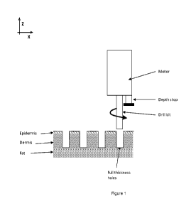
Figure 1 shows an exemplary ablation apparatus having a motor, a depth stop,
and a rotating drill
bit. Also described in Figure 1 is the formation of full thickness holes
(ablation spanning the complete
epidermis and dermis layers) using the ablation apparatus.
Figures 2A and 2B show an exemplary ablation drill bit (a spoon bit). Figure
2A is a front view of
the drill bit having a u-shaped cutting edge. Figure 2B is a side view of the
drill bit having a hemispherical
shape with flat surface (front) providing dual cutting edges that may be
rotated around the drill bit axis.
Figures 3A and 3B show exemplary wire or fiber ablation apparatuses. Figure 3A
depicts a
curved wire attached to the bottom and top ends of a needle. The needle
provides an axis of rotation,
allowing the wire to be rotated, thus causing the wire to remove a volume of
tissue. The shape of the wire
defines the geometry and dimensions of the tissue ablation. Figure 3B depicts
a straight wire attached to
axle or needle. The straight wire is attached to the axle at only one end,
allowing the wire an additional
degree of freedom during rotation (e.g., moving perpendicular to the
longitudinal axis of the axle).
Figure 4 is a depiction of an exemplary blade array ablation apparatus, each
blade apparatus
having a square geometry and a cutting edge around the bottom surface. The
blade apparatuses are
arranged in an array, thus allowing for ablation of multiple tissue portions
with a single array device.
Figures 5A and 5B provide exemplary high-pressure fluid jet ablation
apparatuses having a
cylindrical tube structure with a series of holes to eject the fluid in a
coherent stream (e.g., a fluid jet).
Figure 5A is a schematic of a high pressure fluid ablation apparatus
projecting fluid jets onto the exterior
surface of the tissue, thus forming a series of ablated tissue portions.
Figure 5B is a schematic of a high-
pressure fluid ablation apparatus inserted under the tissue and projecting
fluid jets to the interior of the
tissue, thus forming a series of ablated tissue portions.
Figures 6A and 6B provide exemplary cryosurgery apparatus having a base to
support an array
of tubes, probes, or needles. Figure 6A depicts an array of cryoprobes, each
of which may ablate tissue
at the interface between the probe and the tissue. Figure 6B depicts an array
of cryoneedles, each of
which may ablate tissue with cold temperature upon contact.
11
CA 02920662 2016-02-05
WO 2015/021434
PCT/US2014/050426
Figure 7 shows an exemplary chemical ablation apparatus array having a series
of needles
capable of delivering a chemical or bioactive agent. Figure 7 depicts the
chemical or bioactive ablation
apparatus having a multi-hole needle, in which holes along the cylindrical
body of the needle allow for
transfer of a chemical or bioactive agent at a controlled depth or location.
Figures 8 shows an exemplary electroporation apparatus for ablation of tissue
having an array of
miniature needle-electrodes, each of which has an active electrode and a
return electrode to form a
bipolar electrode pair, and a generator to supply electrical energy to the
electrodes.
Figure 9 shows an exemplary electrode or needle-electrode having a cylindrical
body made of an
electrically insulating material, a single bi-polar electrode where the active
and return electrodes are
separated by the insulating material.
Figures 10A and 10B show an exemplary tissue removal array apparatus having a
support layer
and an adhesive layer. Figure 10A depicts a flat adhesive layer covering the
support layer and removal
of tissue by adhesion of the tissue to the adhesive layer. Figure 10B depicts
adhesive layers affixed to
the ends of probes attached to the support layer. Figure 10B also depicts the
removal of tissue by
adhesion of the tissue to the adhesive layer on the end of the probe.
Figure 11 shows an exemplary tissue removal array apparatus having a housing
which can
sustain a vacuum and an array of holes. Figure 11 depicts the removal of
tissue by adherence of tissue
by a partial or complete vacuum seal to a hole of the array.
Figure 12 shows an exemplary tissue removal apparatus having a thermal
ablation source (e.g., a
laser) and a micro-coring or blade ablation apparatus. Figure 12 depicts an
exemplary method of tissue
removal in which the blade ablation device isolates the tissue to be ablated
from the surrounding tissue.
Once the tissue is isolated, a thermal ablation device can ablate the tissue
inside the blade ablation
device, thus removing the tissue. The blade ablation device insulates the
surrounding tissue from the
thermal ablation, thus preventing coagulation of the surrounding tissue.
Figure 13 shows an exemplary tissue positioning apparatus including two
cylindrical rods to
provide tension to a tissue area prior to, during, or after ablation or tissue
removal. The application of
tension to the skin region may provide a flat, more even surface for skin
treatment.
Figure 14 shows an exemplary tissue positioning apparatus having a series of
micro-hooks that
can be attached to and hold tension in a tissue or skin region. The micro-
hooks may be distributed to
provide tension to the skin in order to provide a tensioned or flat surface in
a variety of geometric
configurations (shown as square region in Figure 14).
Figure 15 shows an exemplary tissue positioning apparatus having a tube for
applying vacuum
around a tissue area to be ablated. The vacuum provides a seal between the
tube and the tissue region,
thus providing tension across the area. An ablation apparatus (shown as an
array of needles) may be
included inside the vacuum tube to ablate the skin region while the vacuum
positions the tissue.
Figure 16 shows an exemplary tissue positioning apparatus having a housing
configured to
control the temperature at the tissue interfacing surface and providing access
through the housing for an
ablation apparatus or array of ablation apparatuses. The temperature at the
interface between the
positioning device and the tissue surface is lowered until the tissue is held
in place by the device.
Figure 17 shows an exemplary tissue positioning apparatus having a housing
including an
adhesive layer on one surface and providing access through the housing for an
ablation apparatus or
12
CA 02920662 2016-02-05
WO 2015/021434
PCT/US2014/050426
array of ablation apparatuses. A tissue layer under tension may adhere to the
adhesive layer, thus
positioning and providing tension to the tissue layer.
Figure 18 shows the healing progression after treatment with micro-coring
needles on the skin of
a Yorkshire pig.
Figure 19 shows photographs of areas of the abdomen of human subjects treated
with different
needle sizes immediately after treatment.
Figure 20 shows several graphs indicating the change in linear
dimension/surface area of a
treated square area (21G/10% or 22G/10%) in comparison with a contra-lateral
non-treated area of
similar dimension (control).
Figure 21 shows a sequence of photographs taken before and after treatment of
abdominal skin
of a human subject.
Figure 22 shows an exemplary tissue positioning apparatus including two
cylindrical pinching
rods to provide tension (e.g., a compressive force applied across the skin,
indicated by arrows) to a tissue
area. The application of tension to the skin region may provide a protruded
surface region of the skin in
which the derm is is lifted from underlying layers (e.g., subcutaneous fat and
muscle), for skin treatment
using micro-corning needles placed between the pinching rods.
Figure 23 shows an exemplary tissue positioning apparatus having a series of
needles ("needle
grippers") that surround micro-corning needles to attach and hold tension
(e.g., a gripping force) in a
tissue or skin region. The needle grippers may be inserted in the skin (arrow
1) and pulled (arrow 2) to
provide tension to the skin and lift the dermis from underlying skin layers.
Top figure provides a side-view
and bottom figure provides a top-view of the apparatus.
Detailed Description
This invention relates to methods and devices for treating skin (e.g.,
eliminating tissue volume,
tightening skin, lifting skin, and/or reducing skin laxity) by selectively
opening or closing a plurality of
wounds or holes (e.g., ablated tissue portions) formed by ablation (e.g.,
incision or excision of tissue)
without thermal energy being imparted to the surrounding (e.g., non-ablated)
tissue. For example, non-
thermal ablation can be performed by fractional ablation of the epidermal
and/or dermal layer of the skin
using a mechanical method, such as a hollow coring needle, a drill, a
microauger, a tube comprising
cutting teeth, a spoon bit, a wire, or a fiber, by a fractional ablation using
a high-pressure fluid jet, by
fractional cryosurgery using a cryoprobe or cryoneedle, by a fractional
chemical ablation, by fractional
electroporation, by a femtosecond laser, and/or by fractional vacuum ablation.
The methods and
apparatuses of the invention also include skin removal methods. Thermal
ablation methods may be
used, such as fractional laser ablation or fractional radio-frequency (RF)
ablation, to remove portions of a
skin region to be ablated once the region is thermally isolated from the
surrounding tissue, thereby not
transferring thermal energy to the surrounding tissue. The present invention
also features tissue
positioning methods and apparatuses. The present invention may include methods
and devices for non-
thermal ablation, tissue removal, tissue positioning, and combinations
thereof.
In particular embodiments, the present invention provides one or more of the
following
advantages. First, the methods and devices herein enable visualization of
results in real time during the
course of the treatment. One can envision asking the patient for feedback in
real time during the
13
CA 02920662 2016-02-05
WO 2015/021434
PCT/US2014/050426
treatment and adjusting the tightening to the patient preference. Second, the
apparatuses include micro-
sized features, which can be beneficial for controlling the extent of skin
treatment. Third, the methods
and apparatuses described herein may require less skill than that of a
surgeon. One can envision
treatment of patients in an outpatient setting, rather than requiring an
inpatient, surgical setting. Fourth,
the methods and apparatuses herein constitute minimally invasive techniques,
which can provide more
predictable results and/or risk factors than that for more invasive techniques
(e.g., plastic surgery) or non-
invasive energy-based techniques (e.g., laser, radiofrequency (RF), or
ultrasound). Fifth, the non-thermal
fractional ablation methods and apparatuses herein allow skin tightening, skin
lifting, and reduction of skin
laxity without inducing coagulation in the surrounding tissue. Thermal
ablation techniques prevent and/or
inhibit skin tightening by allowing coagulation of the tissue and formation of
rigid tissue cores that cannot
be compressed. Sixth, the methods and apparatuses herein can allow for rapid
closing of holes or slits
after treating the skin (e.g., within a few seconds after treating skin, such
as within ten seconds), thereby
minimizing the extent of bleeding and/or clotting within the holes or slits
and/or scar formation. Seventh,
the methods and apparatuses herein can be useful for maximizing the tightening
effect while minimizing
healing time by optimizing tightening (e.g., by controlling the extent of skin
pleating, such as by increasing
the extent of skin pleating for some applications or skin regions and by
decreasing the extent of skin
pleating for other applications or skin regions, as described herein). Eighth,
the methods and
apparatuses for tissue removal described herein provide efficient clearance of
partially ablated tissue and
debris from ablated tissue portions, thus reducing the time for healing and
improving the skin tightening
treatment. Finally, the methods and apparatuses for skin positioning described
herein allow for efficient
and effective positioning of skin prior to, during, and after ablation and/or
tissue removal. Positioning the
skin is critical to control skin-tightening direction and ensure ablation
occurs in the desired location and
desired dimensions.
In some embodiments, apparatuses and methods of the invention allow for the
treatment of skin
with varied thickness. Skin regions vary in thickness depending on the
location on the body. For
example, Kakasheva-Mazenkovska et al., (Contributions, Soc. Biol. Med. Sci.,
MASA, XXXII, 2, p. 119-
128 (2011), incorporated by reference herein in its entirety) describes thin
skin regions for 23-53 year old
adults as including the anterior lower leg (average skin thickness of 1.7 mm)
and the cheeks (average
skin thickness of 2.1 mm) and thick skin regions as the anterior leg (average
skin thickness of 4.9 mm,
e.g., in the anterior upper leg) and the gluteus (average skin thickness of
5.2 mm). The thinnest skin
region observed across all age groups studied was about 0.9 mm, while the
thickest skin region observed
across all age groups was about 5.9 mm. To allow for effective skin
tightening, ablative tissue portions
with a diameter of between 100 pm and 800 pm (e.g., 100, 200, 300, 400, 500,
600, 700, 800 pm) may
be desirable. In some embodiments, ablative tissue portions with a diameter of
between 200 pm and 700
pm may be desirable. In some embodiments, ablative tissue portions with a
diameter of between 300 pm
and 500 pm may be desirable. In other embodiments, ablative tissue portions
with a diameter of between
500 pm and 800 pm may be desirable. Maintaining the desired diameter may
require the ablation
apparatus to provide width to depth ratios across a large range (e.g., from
1:0.3 to 1:75).
14
CA 02920662 2016-02-05
WO 2015/021434
PCT/US2014/050426
Ablated Tissue Portions
The present invention features methods, apparatuses and devices for generating
ablated tissue
portions having various geometric dimensions. For instance, the tissue
portions can have a width to
depth ratio of between about 1:0.3 to about 1:75. In another non-limiting
example, the tissue portions
have a change in width as a function of depth (e.g., a change in width of
between about 10 pm to about
1000 pm as a function of depth, e.g., 10 pm to 50 pm, 10 pm to 100 pm, 10 pm
to 250 pm, 10 pm to 500
pm, 10 pm to 750 pm, 25 pm to 50 pm, 25 pm to 100 pm, 25 pm to 250 pm, 25 pm
to 500 pm, 25 pm to
750 pm, 25 pm to 1000 pm, 50 pm to 100 pm, 50 pm to 250 pm, 50 pm to 500 pm,
50 pm to 750 pm, 50
pm to 1000 pm, 75 pm to 100 pm, 75 pm to 150 pm, 75 pm to 200 pm, 75 pm to 250
pm, 75 pm to 300
pm, 75 pm to 350 pm, 75 pm to 400 pm, 75 pm to 450 pm, 75 pm to 500 pm, 75 pm
to 600 pm, 75 pm to
750 pm, 75 pm to 900 pm, 75 pm to 1000 pm, 100 pm to 200 pm, 100 pm to 250 pm,
100 pm to 300 pm,
100 pm to 350 pm, 100 pm to 400 pm, 100 pm to 450 pm, 100 pm to 500 pm, 100 pm
to 750 pm, 100 pm
to 900 pm, 100 pm to 1000 pm, 150 pm to 250 pm, 150 pm to 500 pm, 150 pm to
750 pm, 150 pm to
1000 pm, 200 pm to 250 pm, 200 pm to 500 pm, 200 pm to 750 pm, 200 pm to 1000
pm, 250 pm to 500
pm, 250 pm to 750 pm, 250 pm to 1000 pm, 400 pm to 500 pm, 400 pm to 750 pm,
400 pm to 1000 pm,
500 pm to 750 pm, 500 pm to 1000 pm, or 750 pm to 1000 pm).
In yet other embodiments, the tissue portions can include a serrated cross-
sectional dimension.
In some embodiments the ablated tissue portions of the invention have at least
one dimension between
about 10 gm and about 2 mm. In other embodiments, an ablated tissue portion
has an areal dimension of
less than about 2.0 mm2. In additional embodiments, an ablated tissue portion
has a volume of less than
about 6.0 mm3. These embodiments are further described below.
An ablated tissue portion may have specific dimensions. In some embodiments,
an ablated
tissue portion has at least one dimension in a range of about 10 pm to about 2
mm (e.g., about 10 pm to
500 pm, about 10 pm to 100 pm, 10 pm to 250 pm, 10 pm to 500 pm, 10 pm to 750
pm, 10 pm to 1 mm,
10 pm to 1.5 mm, 10 pm to 2 mm, about 50 pm to 100 pm, 50 pm to 250 pm, 50 pm
to 500 pm, 50 pm to
750 pm, 50 pm to 1 mm, 50 pm to 1.5 mm, 50 pm to 2 mm, 100 pm to 250 pm, 100
pm to 500 pm, 100
pm to 750 pm, 100 pm to 1 mm, 100 pm to 1.5 mm, 100 pm to 2 mm, 250 pm to 500
pm, 250 pm to 750
pm, 250 pm to 1 mm, 250 pm to 1.5 mm, 250 pm to 2 mm, 500 pm to 750 pm, 500 pm
to 1 mm, 500 pm
to 1.5 mm, 500 pm to 2 mm, 750 pm to 1 mm, 750 pm to 1.5 mm, or 750 pm to 2
mm). In some
embodiments an ablated tissue portion has an areal dimension less than about 2
mm2 and/or a volumetric
dimension that is less than about 6 mm3. The ablated tissue portion may have
an areal dimension in a
range of about 0.001 mm2 to about 2 mm2. In some embodiments, ablated tissue
portions have an areal
dimension less than about 0.2 mm2.
In some embodiments, an ablated tissue portion may form a hole in the skin
region, where the
diameter or width of the hole is less than about 1.0 mm (e.g., less than about
1.0 mm, 750 pm, 500 pm,
250 pm, 100 pm, 50 pm, or 10 pm). The ablated tissue portion may form a hole
in the skin region, where
the diameter or width is in a range of about 0.01 mm to about 2 mm (e.g.,
about 0.01 mm to 0.05 mm,
0.01 to 0.1 mm, 0.01 mm to 0.25 mm, 0.01 mm to 0.5 mm, 0.01 mm to 0.75 mm,
0.01 mm to 1 mm, 0.01
mm to 1.5 mm, 0.01 mm to 2 mm, 0.05 to 0.1 mm, 0.05 mm to 0.25 mm, 0.05 mm to
0.5 mm, 0.05 mm to
0.75 mm, 0.05 mm to 1 mm, 0.05 mm to 1.5 mm, 0.05 mm to 2 mm, 0.1 mm to 0.25
mm, 0.1 mm to 0.5
mm, 0.1 mm to 0.75 mm, 0.1 mm to 1 mm, 0.1 mm to 1.5 mm, 0.1 mm to 2 mm, 0.25
mm to 0.5 mm, 0.25
CA 02920662 2016-02-05
WO 2015/021434
PCT/US2014/050426
mm to 0.75 mm, 0.25 mm to 1 mm, 0.25 mm to 1.5 mm, 0.25 mm to 2 mm, 0.5 mm to
0.75 mm, 0.5 mm
to 1 mm, 0.5 mm to 1.5 mm, 0.5 mm to 2 mm, 0.75 to 1 mm, 0.75 to 1.5 mm, or
0.75 to 2 mm, or any
ranges described herein). In some embodiments, the volumetric dimension that
is less than or equal to
about 6 mm3 (e.g., as described herein) or between about 0.001 mm3 and 6 mm3
(e.g., as described
herein). In particular embodiments, ablated tissue portions are discrete
incised tissue or excised tissue
portions.
The ablated tissue portion can have any combination of the dimensions
described herein. For
instance, in some non-limiting embodiments, the ablated tissue portion has at
least one dimension that is
less than about 2 mm and an areal dimension that is less than about 2 mm2. In
other embodiments, the
ablated tissue portion has at least one dimension that is less than about 2 mm
and a volumetric
dimension that is less than about 6 mm3. In yet other embodiments, the ablated
tissue portion has at
least one dimension that is less than about 2 mm and an areal dimension that
is less than about 2 mm2
and a volumetric dimension that is less than about 6 mm3. In some embodiments,
the ablated tissue
portion has an areal dimension that is less than about 2 mm2 and a volumetric
dimension that is less than
about 6 mm3.
Width-to-depth Ratio
The present invention allows for tissue portions having particular width-to-
depth ratios. Benefits
for optimizing such ratios include improved skin tightening, treatment of thin
skin regions (e.g., lower
anterior leg and cheeks), treatment of thick skin (e.g., anterior leg and
gluteus), and improving skin
rejuvenation (e.g., skin texture, color, and/or architecture). More
importantly, an optimized width to depth
ratio minimizes the risk of scarring while maximizing skin tightening. Non-
thermal ablation forming
ablated tissue portions with specific width to depth ratios improves healing
time, treatment to abnormal
skin areas, and increase the ability to tune hole depth and diameter to the
treatment objective.
Exemplary width to depth ratios include ratios between 1:0.3 to 1:1 (e.g.,
1:0.3 to 1:1, 1:0.35 to 1:1, 1:0.4
to 1:1, 1:0.45 to 1:1, 1:0.5 to 1:1, 1:1 to 0.55 to 1:1, 1:0.6 to 1:1, 1:0.65
to 1:1, 1:0.7 to 1:1, 1:0.75 to 1:1,
1:0.8 to 1:1, 1:0.85 to 1:1, 1:0.9 to 1:1, 1:0.95 to 1:1, 1:0.3 to 1:0.95,
1:0.35 to 1:0.95, 1:0.4 to 1:0.95,
1:0.45 to 1:0.95, 1:0.5 to 1:0.95, 1:0.95 to 0.55 to 1:0.95, 1:0.6 to 1:0.95,
1:0.65 to 1:0.95, 1:0.7 to 1:0.95,
1:0.75 to 1:0.95, 1:0.8 to 1:0.95, 1:0.85 to 1:0.95, 1:0.9 to 1:0.95, 1:0.3 to
1:0.9, 1:0.35 to 1:0.9, 1:0.4 to
1:0.9, 1:0.45 to 1:0.9, 1:0.5 to 1:0.9, 1:0.9 to 0.55 to 1:0.9, 1:0.6 to
1:0.9, 1:0.65 to 1:0.9, 1:0.7 to 1:0.9,
1:0.75 to 1:0.9, 1:0.8 to 1:0.9, 1:0.85 to 1:0.9, 1:0.3 to 1:0.85, 1:0.35 to
1:0.85, 1:0.4 to 1:0.85, 1:0.45 to
1:0.85, 1:0.5 to 1:0.85, 1:0.85 to 0.55 to 1:0.85, 1:0.6 to 1:0.85, 1:0.65 to
1:0.85, 1:0.7 to 1:0.85, 1:0.75 to
1:0.85, 1:0.8 to 1:0.85, 1:0.3 to 1:0.8, 1:0.35 to 1:0.8, 1:0.4 to 1:0.8,
1:0.45 to 1:0.8, 1:0.5 to 1:0.8, 1:0.8 to
0.55 to 1:0.8, 1:0.6 to 1:0.8, 1:0.65 to 1:0.8, 1:0.7 to 1:0.8, 1:0.75 to
1:0.8, 1:0.3 to 1:0.75, 1:0.35 to
1:0.75, 1:0.4 to 1:0.75, 1:0.45 to 1:0.75, 1:0.5 to 1:0.75, 1:0.75 to 0.55 to
1:0.75, 1:0.6 to 1:0.75, 1:0.65 to
1:0.75, 1:0.7 to 1:0.75, 1:0.3 to 1:0.65, 1:0.35 to 1:0.65, 1:0.4 to 1:0.65,
1:0.45 to 1:0.65, 1:0.5 to 1:0.65,
1:0.65 to 0.55 to 1:0.65, 1:0.6 to 1:0.65, 1:0.3 to 1:0.65, 1:0.35 to 1:0.65,
1:0.4 to 1:0.65, 1:0.45 to 1:0.65,
1:0.5 to 1:0.65, 1:0.65 to 0.55 to 1:0.65, 1:0.6 to 1:0.65, 1:0.3 to 1:0.6,
1:0.35 to 1:0.6, 1:0.4 to 1:0.6,
1:0.45 to 1:0.6, 1:0.5 to 1:0.6, 1:0.6 to 0.55 to 1:0.6, 1:0.3 to 1:0.55,
1:0.35 to 1:0.55, 1:0.4 to 1:0.55,
1:0.45 to 1:0.55, 1:0.5 to 1:0.55, 1:0.3 to 1:0.5, 1:0.35 to 1:0.5, 1:0.4 to
1:0.5, 1:0.45 to 1:0.5, 1:0.5 to
1:0.5, 1:0.3 to 1:0.45, 1:0.35 to 1:0.45, 1:0.4 to 1:0.45, 1:0.3 to 1:0.4,
1:0.35 to 1:0.4, or 1:0.3 to 1:0.35)
16
CA 02920662 2016-02-05
WO 2015/021434
PCT/US2014/050426
and 1:25 to 1:75 (e.g., 1:25 to 1:75, 1:30 to 1:75, 1:35 to 1:75, 1:40 to
1:75, 1:45 to 1:75, 1:50 to 1:75,
1:55 to 1:75, 1:60 to 1:75, 1:65 to 1:75, 1:70 to 1:75, 1:25 to 1:70, 1:30 to
1:70, 1:35 to 1:70, 1:40 to 1:70,
1:45 to 1:70, 1:50 to 1:70, 1:55 to 1:70, 1:60 to 1:70, 1:65 to 1:70, 1:25 to
1:65, 1:30 to 1:65, 1:35 to 1:65,
1:40 to 1:65, 1:45 to 1:65, 1:50 to 1:65, 1:55 to 1:65, 1:60 to 1:65, 1:25 to
1:60, 1:30 to 1:60, 1:35 to 1:60,
1:40 to 1:60, 1:45 to 1:60, 1:50 to 1:60, 1:55 to 1:60, 1:25 to 1:55, 1:30 to
1:55, 1:35 to 1:55, 1:40 to 1:55,
1:45 to 1:55, 1:50 to 1:55, 1:25 to 1:50, 1:30 to 1:50, 1:35 to 1:50, 1:40 to
1:50, 1:45 to 1:50, 1:25 to 1:45,
1:30 to 1:45, 1:35 to 1:45, 1:40 to 1:45, 1:25 to 1:40, 1:30 to 1:40, 1:35 to
1:40, 1:25 to 1:35, 1:30 to 1:35,
or 1:25 to 1:30). Additional width-to-depth ratios are described herein, such
as 1:1 to about 1:20 (e.g.,
any range described herein).
Exemplary ablated tissue portion widths include from about 0.1 mm to about 0.8
mm (e.g., 0.1
mm to 0.8 mm, 0.1 mm to 0.6 mm, 0.1 mm to 0.4 mm, 0.1 mm to 0.2 mm, 0.2 mm to
0.8 mm, 0.2 mm to
0.6 mm, 0.2 mm to 0.4 mm, 0.2 mm to 0.3 mm, 0.3 mm to 0.8 mm, 0.3 mm to 0.6
mm, 0.3 mm to 0.4 mm,
0.4 mm to 0.8 mm, 0.4 mm to 0.6 mm, 0.4 mm to 0.5 mm, 0.5 mm to 0.8 mm, 0.5 mm
to 0.6 mm, 0.6 mm
to 0.8 mm, 0.6 mm to 0.7 mm, or 0.7 mm to 0.8 mm). Exemplary ablated tissue
portion widths includes
0.9 mm to 20 mm (e.g., 0.9 mm to 20 mm, 0.9 mm to 17 mm, 0.9 mm to 14 mm, 0.9
mm to 11 mm, 0.9
mm to 8 mm, 0.9 mm to 5 mm, 0.9 mm to 3 mm, 3 mm to 20 mm, 3 mm to 17 mm, 3 mm
to 14 mm, 3 mm
toll mm, 3 mm to 8 mm, 3 mm to 5 mm, 5 mm to 20 mm, 5 mm to 17 mm, 5 mm to 14
mm, 5 mm to 11
mm, 5 mm to 8 mm, 8 mm to 20 mm, 8 mm to 17 mm, 8 mm to 14 mm, 8 mm to 11 mm,
11 mm to 20
mm, 11 mm to 17 mm, 11 mm to 14 mm, 14 mm to 20 mm, 14 mm to 17 mm, or 17 mm
to 20 mm) and
0.01 mm to 0.25 mm (e.g., 0.01 mm to 0.25 mm, 0.02 mm to 0.25 mm, 0.03 mm to
0.25 mm, 0.05 mm to
0.25 mm, 0.075 mm to 0.25 mm, 0.1 mm to 0.25 mm, 0.15 mm to 0.25 mm, 0.2 mm to
0.25 mm, 0.01 mm
to 0.2 mm, 0.02 mm to 0.2 mm, 0.03 mm to 0.2 mm, 0.05 mm to 0.2 mm, 0.075 mm
to 0.2 mm, 0.1 mm to
0.2 mm, 0.15 mm to 0.2 mm, 0.01 mm to 0.15 mm, 0.02 mm to 0.15 mm, 0.03 mm to
0.15 mm, 0.05 mm
to 0.15 mm, 0.075 mm to 0.15 mm, 0.1 mm to 0.15 mm, 0.01 mm to 0.1 mm, 0.02 mm
to 0.1 mm, 0.03
mm to 0.1 mm, 0.05 mm to 0.1 mm, 0.075 mm to 0.1 mm, 0.01 mm to 0.075 mm, 0.02
mm to 0.075 mm,
0.03 mm to 0.075 mm, 0.05 mm to 0.075 mm, 0.01 mm to 0.05 mm, 0.02 mm to 0.05
mm, 0.03 mm to
0.05 mm, 0.01 mm to 0.03 mm, 0.02 mm to 0.03 mm, 0.03 mm to 0.03 mm, 0.01 mm
to 0.03 mm, 0.02
mm to 0.03 mm, or 0.01 mm to 0.02 mm). Further non-limiting exemplary ablated
tissue portion widths
and/or lengths include from about 0.01 mm to about 20 mm or from about 0.01 mm
to about 2 mm (e.g.,
such as any range described herein).
Changes in Width Along the Depth
The present invention allows for tissue portions having changes in width.
Benefits for optimizing
such changes include improved ablated tissue portion closing (e.g., a larger
diameter at skin surface and
smaller diameter in the skin depth will facilitate hole closing or,
alternatively, a small diameter at skin
surface and larger diameter in skin depth may accelerate closure of the
epidermal layer and therefore
minimize risk of adverse events, such as infections, and minimize healing
time), increased surface area of
the inside of the ablated tissue portion or hole, or improved directional
healing response by having an
offset increase of diameter, thus biasing hole closure upon compression in a
single direction. Exemplary
changes include a change in width of between about 10 pm to about 1000 pm as a
function of depth,
such as any range described herein. In one non-limiting embodiment, the change
is about 100 pm at the
17
CA 02920662 2016-02-05
WO 2015/021434
PCT/US2014/050426
skin surface and about 500 pm at the bottom of the dermal layer (e.g., to
minimize closure time of the
epidermal layer, such as reepithelialization). In another non-limiting
embodiment, the change is about
400 pm at the skin surface and between about 0 to about 200 pm at the bottom
of the dermal layer (e.g.,
to facilitate hole mechanical closure).
Serrated Cross-Sectional Dimension
The present invention also allows for tissue portions having a serrated or
scalloped cross-
sectional dimension. Benefits for serrated cross-sectional dimensions include
increased surface area for
binding tissue together with or without glues or sealants, thus improving the
strength of a closure. In
addition, serrated edges provide a mechanism to bias hole closing. For
example, the serrated internal
pattern of an ablated tissue portion may be configured such that when
compressed in a first direction, the
serrated structures from opposite sides of the wound interlock, thus allowing
complete closure of the hole.
In some embodiments, the serrated or scalloped cross-sectional dimensions
occur in the x-axis, y-axis, or
xy-axis. In other embodiments, the serrated or scalloped cross-sectional
dimensions occur in the z-axis.
Exemplary serrated cross-sectional dimensions include regular or irregular
ridges or depressions in the
side wall of an ablated tissue portion or hole equal in height to 10% of the
hole diameter. In other
embodiments, the height of the regular or irregular ridges or depressions is
between 5% and 70% of the
diameter of the ablated tissue portion (e.g., between 5% and 10%, 5% and 20%,
5% and 30%, 5% and
40%, 5% and 50%, 5% and 60%, 5% and 70%, 10% and 20%, 10% and 30%, 10% and
40%, 10% and
50%, 10% and 60%, 10% and 70%,. 20% and 30%, 20% and 40%, 20% and 50%, 20% and
60%, 20%
and 70%, 30% and 40%, 30% and 50%, 30% and 60%, 30% and 70%, 40% and 50%, 40%
and 60%,
40% and 70%, 50% and 60%, 50% and 70%, or 60% and 70%).
Ablation Apparatuses and Methods for Non-Thermal Ablation of Tissue
The present invention features methods, apparatuses and devices for generating
ablated tissue
portions (e.g., microwounds or incised or excised tissue portions) without
imparting thermal energy to the
surrounding tissue. Exemplary devices include those which selectively generate
an ablated tissue portion
using a drill, driver (e.g., a pile driver (e.g., a tattoo gun that uses solid
needles), which compresses,
shears, and destroys the tissue as it cycles up and down in the z-axis), wire
or flexible fiber, blade, high
pressure fluid jet, cryoprobes or cryoneedles, chemical treatment, non-thermal
energy, or direct vacuum.
In particular, wounds generated without the use of thermal energy by methods
and devices of this
invention may desirably have an areal dimension of less than 4 mm2 and/or a
volumetric dimension that is
less than about 6 mm3. Methods and devices for non-thermal ablation may form
holes with multiple
diameters along the wound depth. The present invention also features methods
and devices for making
ablated tissue portions with serrated or non-uniform edges along the depth of
the ablated tissue portion.
One or more therapeutic agents (e.g. an anticoagulant) may be added prior to,
during, or after ablation of
tissue.
Drills
The present invention features methods, devices, and apparatuses for rotating
a penetrating
component that may be used to ablate skin in a fractional pattern. The
mechanical fractional ablation
18
CA 02920662 2016-02-05
WO 2015/021434
PCT/US2014/050426
apparatus includes a motor (e.g., electric or pneumatic motor) for rotation of
a penetrating component or
an array of penetrating components.
The penetrating component is positioned to be in contact with the skin outer
surface (epidermis),
the motor is activated, and the apparatus is pushed toward the skin until it
reaches a pre-set depth. An
optional adjustable depth stop may limit the ablation depth. The ablation
depth may be adjusted to
remove only a portion of the skin (i.e., epidermis and part of the dermis) or
to remove the full epidermis
and dermis thickness. Full thickness removal may be beneficial for skin
tightening. Removing only part
of the thickness of the skin region may be beneficial for improvement of the
tissue texture and/or color
and/or to accelerate healing. In one embodiment, a penetrating component may
be a drill bit having
spiral channels along its long axis to carve away the tissue and create the
ablation and carry the tissue up
the bit as it turns.
Ablative apparatuses may be designed to spin at a range of rotational speeds
(e.g., greater than
50 rpm or between about 50 rpm to about 2500 rpm) that may be selected to
produce the desired effect
(e.g., ablation creates well defined regions of tissue with clean margins),
while reducing or eliminating
undesirable effects, such as heat production and tissue shredding. In another
embodiment, a drill
includes micro-augers in which the penetrating component consists of a spiral
flange for cutting into the
tissue and conveying the tissue up to the surface of the skin for elimination.
In particular non-limiting
embodiments, it might be beneficial to work at lower speed to minimize heating
of the tissue and to
improve cutting performance through soft materials. In this context, an
exemplary non-limiting maximal
rotational speed is about 2500 rpm while allowing for very low speeds above
about 50 rpm. Exemplary
rotational speeds include from about 50 rpm to about 2500 rpm (e.g., 50 rpm to
100 rpm, 50 rpm to 250
rpm, 50 rpm to 500 rpm, 50 rpm to 750 rpm, 50 rpm to 1000 rpm, 50 rpm to 1500
rpm, 50 rpm to 2000
rpm, 50 rpm to 2500 rpm, 75 rpm to 100 rpm, 75 rpm to 250 rpm, 75 rpm to 500
rpm, 75 rpm to 750 rpm,
75 rpm to 1000 rpm, 75 rpm to 1500 rpm, 75 rpm to 2000 rpm, 75 rpm to 2500
rpm, 100 rpm to 250 rpm,
100 rpm to 500 rpm, 100 rpm to 750 rpm, 100 rpm to 1000 rpm, 100 rpm to 1500
rpm, 100 rpm to 2000
rpm, 100 rpm to 2500 rpm, 250 rpm to 500 rpm, 250 rpm to 750 rpm, 250 rpm to
1000 rpm, 250 rpm to
1500 rpm, 250 rpm to 2000 rpm, 250 rpm to 2500 rpm, 500 rpm to 750 rpm, 500
rpm to 1000 rpm, 500
rpm to 1500 rpm, 500 rpm to 2000 rpm, 500 rpm to 2500 rpm, 750 rpm to 1000
rpm, 750 rpm to 1500
rpm, 750 rpm to 2000 rpm, 750 rpm to 2500 rpm, 1000 rpm to 1500 rpm, 1000 rpm
to 2000 rpm, 1000
rpm to 2500 rpm, 1500 rpm to 2000 rpm, 1500 rpm to 2500 rpm, or 2000 rpm to
2500 rpm).
Alternatively, a micro-auger may be configured to move tissue and debris to
another region where
it may be eliminated. For example, the flange may have a spiral configured to
push the cuttings
downward away from the site of ablation. A spiral channel or flange may be on
a portion of the
penetrating component or along its entire length. The cuttings may be removed
in a second step or left to
be resorbed by the body in a subdermal location.
Many drill bit designs are contemplated, including drill bits which are
employed for use in non-
medical fields such as construction, engineering, and general mechanical
applications. The drill bits may
be fashioned from a wide variety of materials; non-limiting examples include:
metals, plastics, silicon,
crystalline materials, and non crystalline materials. The drill bits may be
hollow or solid. Hollow drills may
be fashioned to have a channel through their core that conveys a vacuum for
elimination of tissue
cuttings. Penetrating components may be cooled or heated to control the
temperature of the surrounding
19
CA 02920662 2016-02-05
WO 2015/021434
PCT/US2014/050426
tissue. The pattern of the flange or spiral channels may be fashioned to
optimize the ablation and/or
transport of tissue such as adipose tissue, derm is, or epidermal tissue.
In another embodiment, drilling through soft tissue (e.g., skin) may be
achieved with a hollow tube
having a sharp cutting edge (e.g., a paper drill). Ablated tissue is captured
in the hollow drill bit.
Alternatively, the hollow tube may be pushed through the skin by a high-
frequency vibrating mechanism
(e.g., a piezo actuator operated at high frequency). In another alternative, a
tube having a sharp edge
and cutting teeth (e.g., a hole saw) may be used. Similarly, tissue is
captured in the hollow drill bit. A
spoon bit may also be used to ablate tissue. A spoon bit is constituted of a
grooved shank and is shaped
like the bowl of a spoon. The edges of the bit are sharp and cut through
tissue.
In another embodiment, tissue may be hardened before drilling, e.g., by local
freezing. This
allows use of twist drill bits having a cutting point at the tip of a
cylindrical shaft with helical flutes for
removal of cut tissue. Freezing may be achieved by application of a freezing
agent (e.g. liquid nitrogen or
argon gas) or by application of a freezing probe on the skin surface.
Alternatively, a drill bit may be
cooled such that it causes flash freezing of the tissue immediately
surrounding the area of contact with
the drill bit. Freezing of the tissue in this manner may enable an improved
ablation pattern and/or reduce
pain and bleeding during the procedure.
Exemplary drill bits for any of the above embodiments are a twist bit, hole
saw bit, paper drill bit,
step drill bit, unibit, lip or spur bit (brad point bit), spade bit, spoon
bit, Forstner bit, center bit, auger bit,
gimlet bit, installer bit, two-flute bit, three-flute bit, core drill bit,
countersink bit, gun drill bit, microauger,
tube with cutting teeth, and other drill bits known in the art.
Drill bits according to any of the above embodiments of the invention can be
made from many
materials, including metals, metal alloys, shape memory materials, plastics,
ceramics, and composite
materials such as metals and metal alloys coated with black oxide, titanium
nitride, titanium aluminum
nitride, titanium carbon nitride, diamond powder, zirconium nitride, and other
hardening agents and
combinations of the materials herein.
Wires and Fibers
The invention further features devices, methods, and apparatuses that include
wires (e.g. metallic
or non-metallic wires or fibers) or an array of wires or fibers that can be
used to ablate skin in a fractional
pattern.
In one embodiment, a wire is attached to a very thin axle (e.g., a needle) at
one point or at two
points to form a loop. The axle has a point at one end to facilitate insertion
into the skin. The other end
of the axle may be attached to a motor that drives the axle. When the motor is
activated, the axle rotates
along the longitudinal axis, driving the wire loop at high speed to cut
through the skin tissue. The axle
can rotate at any useful speed, such as about 500 rpm to about 5000 rpm (e.g.,
from 500 rpm to 1000
rpm, 500 rpm to 2000 rpm, 500 rpm to 3000 rpm, 500 rpm to 4000 rpm, 750 rpm to
1000 rpm, 750 rpm to
2000 rpm, 750 rpm to 3000 rpm, 750 rpm to 4000 rpm, 750 rpm to 5000 rpm, 1000
rpm to 2000 rpm,
1000 rpm to 3000 rpm, 1000 rpm to 4000 rpm, 1000 rpm to 5000 rpm, 1500 rpm to
2000 rpm, 1500 rpm
to 3000 rpm, 1500 rpm to 4000 rpm, 1500 rpm to 5000 rpm, 2000 rpm to 3000 rpm,
2000 rpm to 4000
rpm, 2000 rpm to 5000 rpm, 2500 rpm to 3000 rpm, 2500 rpm to 4000 rpm, or 2500
rpm to 5000 rpm).
CA 02920662 2016-02-05
WO 2015/021434
PCT/US2014/050426
In another embodiment, a wire is attached to an axle having the same diameter
as the hole to be
created. The wire may be attached off-center and to the outer diameter of the
axle. The wire is parallel
to the long axis of the axle. When the axle is rotating at high speed along
its long axis, the wire trajectory
defines a cylinder, co-axial with and of the same diameter as the axle. The
wire or fiber may be inserted
in the skin while the axle is rotating to cut a cylindrical hole. In one
embodiment, the wire or fiber is of a
fixed shape and length. In other embodiments, the shape and length of the wire
may be changed to
produce different ablation diameters along the Z axis. Specifically, a larger
diameter hole portion may be
produced on top of a narrower diameter hole portion. This may be desirable
when targeting certain
tissues for ablation such as subdermal fat. A wire or fiber may be fed through
a hollow channel in the
penetrating component. The amount of wire fed through the penetrating
component may be adjusted as
the component penetrates the tissue. The wire/fiber may also be retracted as
the penetrating component
is translated through the tissue, thus creating a gradient of hole diameters
along the hole depth. The wire
or fiber may be stiff and possess shape memory, may be flexible, or possess a
mixture of the both rigidity
and ductility along the length of the wire or fiber. In some embodiments, the
wire or fiber includes preset
volumetric contours. In other embodiments, the wire or fiber includes vertical
mire loops (e.g., to slice
away tissue, like potato peeler from the surface across the x-y plane of the
skin).
In other embodiments a fiber can be used in place of a wire. Fibers can be
attached at a single
point or at dual points along the axis of a rotating member. Fibers can be
rigid (e.g. a hard plastic such
as PEEK) or ductile (e.g., a flexible plastic such as polyethylene). The fiber
can be a composite (e.g.,
glass filled polypropylene) to improve or alter the mechanical properties.
Many types of wires or fibers can be used in the present invention. For
example, wires can be
single stranded, braided, or composites of individual wires of a single or
multiple gauges or diameters.
Wires can have diameters such that the wire can be attached to a rotating
component and ablate tissue
within the desired hole diameter. For example, a wire can have a diameter
ranging from 30 gauge to 40
gauge (American gauge wire, 255 pm to 80 pm). The diameter of the wire can be
less than 80 gm. In
some embodiments, the length of the wire can be between about 100 pm and about
5000 pm (e.g., 100
pm and 250 pm, 100 pm and 500 pm, 100 pm and 750 pm, 100 pm and 1000 pm, 100
pm and 1500 pm,
100 pm and 2000 pm, 100 pm and 2500 pm, 100 pm and 3000 pm, 100 pm and 3500
pm, 100 pm and
4000 pm, 100 pm and 4500 pm, 200 pm and 250 pm, 200 pm and 500 pm, 200 pm and
750 pm, 200 pm
and 1000 pm, 200 pm and 1500 pm, 200 pm and 2000 pm, 200 pm and 2500 pm, 200
pm and 3000 pm,
200 pm and 3500 pm, 200 pm and 4000 pm, 200 pm and 4500 pm, 300 pm and 500 pm,
300 pm and
750 pm, 300 pm and 1000 pm, 300 pm and 1500 pm, 300 pm and 2000 pm, 300 pm and
2500 pm, 300
pm and 3000 pm, 300 pm and 3500 pm, 300 pm and 4000 pm, 300 pm and 4500 pm,
400 pm and 500
pm, 400 pm and 750 pm, 400 pm and 1000 pm, 400 pm and 1500 pm, 400 pm and 2000
pm, 400 pm
and 2500 pm, 400 pm and 3000 pm, 400 pm and 3500 pm, 400 pm and 4000 pm, 400
pm and 4500 pm,
500 pm and 750 pm, 500 pm and 1000 pm, 500 pm and 1500 pm, 500 pm and 2000 pm,
500 pm and
2500 pm, 500 pm and 3000 pm, 500 pm and 3500 pm, 500 pm and 4000 pm, 500 pm
and 4500 pm, 600
pm and 750 pm, 600 pm and 1000 pm, 600 pm and 1500 pm, 600 pm and 2000 pm, 600
pm and 2500
pm, 600 pm and 3000 pm, 600 pm and 3500 pm, 600 pm and 4000 pm, 600 pm and
4500 pm, 700 pm
and 750 pm, 700 pm and 1000 pm, 700 pm and 1500 pm, 700 pm and 2000 pm, 700 pm
and 2500 pm,
700 pm and 3000 pm, 700 pm and 3500 pm, 700 pm and 4000 pm, 700 pm and 4500
pm, 800 pm and
21
CA 02920662 2016-02-05
WO 2015/021434
PCT/US2014/050426
1000 pm, 800 pm and 1500 pm, 800 pm and 2000 pm, 800 pm and 2500 pm, 800 pm
and 3000 pm, 800
pm and 3500 pm, 800 pm and 4000 pm, 800 pm and 4500 pm, 900 pm and 1000 pm,
900 pm and 1500
pm, 900 pm and 2000 pm, 900 pm and 2500 pm, 900 pm and 3000 pm, 900 pm and
3500 pm, 900 pm
and 4000 pm, 900 pm and 4500 pm, 1000 pm and 1500 pm, 1000 pm and 2000 pm,
1000 pm and 2500
pm, 1000 pm and 3000 pm, 1000 pm and 3500 pm, 1000 pm and 4000 pm, 1000 pm and
4500 pm, 1500
pm and 2000 pm, 1500 pm and 2500 pm, 1500 pm and 3000 pm, 1500 pm and 3500 pm,
1500 pm and
4000 pm, 1500 pm and 4500 pm, 2000 pm and 2500 pm, 2000 pm and 3000 pm, 2000
pm and 3500 pm,
2000 pm and 4000 pm, or 2000 pm and 4500 pm).
Blades
The invention also features blades or an array of blades that may ablate skin
in a fractional
pattern. In one embodiment, a cylindrical blade having the diameter of the
hole to be generated may be
pushed into the skin to cut a cylindrical hole (e.g., a cylindrical tube with
a blade edge or a micro-coring
component). The blade may be rotated to assist in the tissue ablation. The
depth of the hole may be
controlled by manually controlling the depth of the blade or by using a depth
stop. The ablated tissue
portion inside the cylindrical blade may be removed with a pin, vacuum,
positive pressure or other
methods described herein.
In another embodiment, straight blade(s) may be used to generate holes that
are not cylindrical.
Different patterns of holes may be cut depending on the geometry and number of
blades (e.g. triangle,
hexagon, or octagon). Blades may be inserted into the tissues with sufficient
force and speed to produce
a desired effect. Alternatively, the blades may be oscillated or vibrated at
high frequency to enable
insertion at lower speed and force (e.g., similar to vibration enhanced
commercially available electric
knives and scalpels).
In another embodiment, a plurality of blades is assembled into an array to
simultaneously cut
multiple holes. For example, four blades may be assembled as to generate a
blade with a square hole.
Several of these square blades may be combined to form an array of blades. The
square blades may be
spaced within the array and sized to provide a 5-40% areal removal of skin
once pressed into the tissue
and removed. The ablated tissue portions may be closed with a variety of
methods (e.g., dressings,
sutures, closures, and other compressive means). Upon healing the skin volume
will be reduced, thus
tightening or reducing the laxity of the skin region.
In another embodiment, the pattern of ablations may be adjusted with a variety
of flat cutting
blades by changing the pattern of cuts in the tissue. For example, diamond
patterns or octagonal
patterns may be produced with a single blade or multiple cutting blades.
Ablations of desired geometries
may be generated by sequential insertion of a single blade in which the
orientation of the blade is
changed with respect to the previous incision.
The removal of the ablated tissue (e.g., the circumscribed tissue region) may
be accomplished
with a variety of mechanisms. Mechanical means (e.g., a hook, a scoop, an
adhesive), negative pressure
(e.g., a vacuum), or positive pressure (e.g., fluid or gas pressure) may be
used to remove the ablated
tissue portion from the ablation apparatus.
Non-limiting exemplary blades include; taps, cutters, corers, reamers, awls,
broaches, step core,
pinch, core, rotary, and punches. Exemplary blade materials include: metal
(e.g., a stainless steel tube,
22
CA 02920662 2016-02-05
WO 2015/021434
PCT/US2014/050426
304 stainless steel, a surgical stainless steel), metal alloys, polymer or
plastic, glass, ceramics, or other
structural materials. Blades may be a composite of one or more materials
including: metals and metal
alloys coated with black oxide, titanium nitride, titanium aluminum nitride,
titanium carbon nitride, diamond
powder, zirconium nitride, and other hardening agents and combinations of
materials such as polymers,
plastics, ceramics and other structural materials. Additional exemplary
coatings include a lubricant, a
low-friction material (e.g., TeflonTm), a chromium coating (e.g., ME-92TM,
such as to increase material
strength), a plastic, a polymer (e.g., nylon or polyethylene), a polished
metal alloy, or the like.
Further, the tubes, blades, pins, and ablation apparatuses can be formed from
any useful
material and optionally coated or chemically treated to promote incision or
excision of a tissue portion
and/or to increase precision or effectiveness for treating the skin region.
Exemplary materials include
metal, a biopsy needle, an epoxy, a glass, a polymer, a plastic, a resin,
another structurally rigid material,
or a similar structure.
High Pressure Fluid Jet
In other embodiments, the invention features high pressure fluid jets or an
array of high pressure
fluid jets that may ablate skin in a fractional pattern.
In one embodiment, an ablation apparatus containing at least one high pressure
fluid jet (e.g.,
fluid pressure of greater than 1380kPa or 200 psi) may be positioned external
to the skin surface. The
high pressure fluid jet is applied to the skin surface, thus producing a hole.
The size of the hole may be
determined by the fluid jet size and length of exposure. For example, to
provide an ablated skin portion
with a shallower depth, the fluid jet may be applied for a shorter time.
Alternatively, to provide an ablated
skin portion with a greater depth or diameter, the fluid jet may be applied to
the skin region for a longer
time. A high pressure fluid jet is a non-thermal ablative mechanism and does
not generate a thermal
injury to the surrounding tissue. An exemplary method for removing excess
fluid, tissue or debris
generated during ablation is using a vacuum source (negative pressure) or a
pressurized air stream
(positive pressure).
Exemplary non-limiting pressures include from about 200 psi to about 100000
psi (e.g., from 200
psi to 1000 psi, 200 psi to 5000 psi, 200 psi to 10000 psi, 200 psi to 50000
psi, 500 psi to 1000 psi, 500
psi to 5000 psi, 500 psi to 10000 psi, 500 psi to 50000 psi, 500 psi to 100000
psi, 750 psi to 1000 psi, 750
psi to 5000 psi, 750 psi to 10000 psi, 750 psi to 50000 psi, 750 psi to 100000
psi, 1000 psi to 5000 psi,
1000 psi to 10000 psi, 1000 psi to 50000 psi, 1000 psi to 100000 psi, 1500 psi
to 5000 psi, 1500 psi to
10000 psi, 1500 psi to 50000 psi, 1500 psi to 100000 psi, 2000 psi to 5000
psi, 2000 psi to 10000 psi,
2000 psi to 50000 psi, 2000 psi to 1 00000 psi, 2500 psi to 5000 psi, 2500 psi
to 1 0000 psi, 2500 psi to
50000 psi, 2500 psi to 100000 psi, 4000 psi to 5000 psi, 4000 psi to 10000
psi, 4000 psi to 50000 psi,
4000 psi to 100000 psi, 5000 psi to 10000 psi, 5000 psi to 50000 psi, 5000 psi
to 100000 psi, 7500 psi to
10000 psi, 7500 psi to 50000 psi, 7500 psi to 100000 psi, 10000 psi to 50000
psi, 10000 psi to 100000
psi, 50000 psi to 100000 psi, or 75000 psi to 100000 psi).
In another embodiment, an ablation apparatus containing fluid jets is inserted
in the fatty layer,
under the derm is and epidermis. The array of high pressure fluid jets emits
fluid at very high pressure to
ablate the tissue above. A low pressure out-flow tube may be positioned on the
surface of the skin to
remove fluid and debris. In another embodiment, a discontinuous fluid flow may
be used to allow removal
23
CA 02920662 2016-02-05
WO 2015/021434
PCT/US2014/050426
of fluid and debris before reactivating the high-pressure jet. In another
embodiment, the jet array can be
moved (e.g., in a circular fashion) in relation to the skin so as to produce
an array of cylindrical ablations.
High pressure fluid jets of the invention may be a coherent fluid stream or an
incoherent fluid
stream. One or more nozzles may be used to form the fluid jet. For example, a
convergent nozzle may
be used which reduces the diameter of the outlet, thus increasing the velocity
of the fluid jet.
Many fluids may be used to make the high pressure fluid jet. Non-limiting
examples include:
aqueous and non aqueous solutions, such as isotonic and non isotonic buffers,
and saline solutions, and
may include additional ingredients that have a desirable medical or aesthetic
activity or utility. Exemplary
additional therapeutic agents include but are not limited to heparin, fibrin,
antibiotics, lidocaine and other
analgesics.
Cryosurgery
Tissue ablation according to the invention may also be accomplished by
cryosurgery, in which
extreme cold is used to destroy tissue. Cryosurgery is a less invasive
alternative to surgery; and
generally has less complications and side effects. Cold temperature is
typically generated with a
cryogen, such as liquid nitrogen (-196 degrees C), carbon dioxide (-78.5
degrees C), argon gas (-185.5
degrees C), and/or dimethyl ether-propane (-41 degrees C), or cold probes.
Ablation of tissue in a fractional pattern may be achieved by cryosurgery.
Ablated columns of
tissue resorb and are replaced by healthy tissue. This fractional ablation
technology is less invasive than
fractional surgical ablation. This results in faster healing and may limit
side effects and other
complications (e.g., no bleeding, lower risk of infection). Following
fractional cryosurgery, a compressive
wound dressing may be applied to the skin to enhance skin tightening.
In one embodiment an array of miniature cold probes is applied to a skin
region. The probes
locally decrease the skin temperature, thus freezing and destroying and/or
ablating the tissue at the skin
region surface. The resulting ablation is superficial (e.g., only at the skin
surface) which provides ablated
tissue portions with high width to depth ratios. Therefore, this technique is
well suited to improvement of
skin texture and color.
In another embodiment, cold needles are inserted into the skin region. This
embodiment allows
ablation of deep skin tissue. One may envision the formation of full depth
skin ablations (i.e. ablation of
the epidermis and derm is layer). Ablated tissue portions spanning both the
epidermis and derm is layers
of the skin are best suited for skin tightening. To maximize the skin
tightening treatment, the ablation is
followed by a compressive wound dressing. The penetrating components may be
temperature controlled
and may consist of a temperature conductive material. The temperature
conductive material may be
brought into proximity with a heat sink. Given the small size of the
penetrating components, such cooling
may occur within seconds or sub-second timeframes. Such temperature conductive
materials include
metals such as copper and stainless steel.
In another embodiment, penetrating components may be fashioned to include
regions composed
of temperature non-conductive (e.g., insulator) materials to help shield
regions of the tissue or imbed
patterns into the tissue from exposure to extremes of temperature. For
example, a cryoneedle can be
coated with an insulating material on only one side, thus leaving the other
side of the needle thermally
conducting. After reducing the temperature of the cryoneedle with a heat sink,
the thermally conductive
24
CA 02920662 2016-02-05
WO 2015/021434
PCT/US2014/050426
side will freeze tissue while the sides coated with an insulator will not,
thus forming asymmetric hole
diameters (e.g. non-circular).
Needles can be cooled by any useful process. In one non-limiting example, one
can envision
attaching the needles to a Peltier cell (heat pump) that cools the needles,
while the other side of the
Pelletier cell is heated and heat is dissipated through radiators. In another
non-limiting example, a
cooling fluid may be circulated in the needle (e.g., the apparatus can include
an internal needle and an
external needle, where the internal needle includes a first material having
conductive properties (e.g., a
metal, such as any described herein) and includes a cryogen within the lumen
of the internal needle,
thereby cooling the external needle). In other embodiments, the external
needle includes a second
material on its distal end (e.g., silver). In yet another non-limiting
example, the needle may be used as a
micro-evaporator in a refrigerating circuit.
Chemical or Bioactive Agents
In another embodiment, chemical or bioactive agents may also be used to
destroy or ablate skin
tissue. Typical chemical or bioactive agents used include trichloracetic acid,
alpha hydroxy acids, beta
hydroxy acids, liquid nitrogen, hypoosmotic fluids, hyperosmotic fluids, and
bioactive proteins (e.g., one or
more hormones, antibodies, and/or enzymes, such as enzymes that liquefy
tissue, such as one or more
proteases, DNases, hyaluronidase, and collagenases, or combinations thereof).
Chemicals or bioactive
agents are used to create an injury, ablated tissue portion, and/or stimulate
new tissue formation.
In one embodiment, tissue may be denatured, ablated, and/or destroyed in a
fractional pattern
with chemical or bioactive agents. For example, an array of needles with side-
holes along the needle
body may be introduced in the skin. The multiple side-holes in the needles
allows for injection of a
chemical or bioactive denaturizing agent at multiple depths, allowing for full-
thickness denaturation of
columns of skin tissue.
In another embodiment, the needle side-holes can be configured to supply a
chemical or
bioactive agent to specific areas along the needle or in a specific pattern.
In addition, the size of the
needle side holes may control the amount of chemical or bioactive agent
delivered to a particular location.
This embodiment allows for the formation of ablated tissue portions with
multiple diameters along the
length, asymmetric structures, and serrated cross-sectional dimension.
Microelectrodes
In yet another embodiment, ablation may be accomplished by non-thermal
irreversible
electroporation, which involves the application of very short bursts of
electricity (microsecond duration
range) at a specific voltage and frequency to form nanopores in the cell
membrane. The electroporation
parameters may be selected to form reversible pores (i.e., the cell may repair
and restore normal
function) or irreversible pores (i.e., the treatment produces cell apoptosis).
The electroporation may be
configured to use a set of parameters such that the energy only affects
targeted tissue. For example, a
specific cell type may be destroyed without affecting an extracellular matrix,
nerves, or blood vessels.
Small electrodes (diameter in the mm range) are typically used for
electroporation.
In one embodiment, a non-thermal irreversible electroporation may be used for
fractional skin
region or tissue ablation. Carefully selected treatment parameters limit the
effect of the electroporation to
CA 02920662 2016-02-05
WO 2015/021434
PCT/US2014/050426
the skin region, thus leaving blood vessels and nerve fibers substantially
unaffected and without
significant heating of the surrounding tissue. For example, a pair of needle
electrodes may be inserted
into a skin region. A first electrode of the electrode pair may be an active
electrode and the second
electrode of the pair may be a return electrode. The ablated tissue portion
occurs in the tissue volume
between the electrode pair. The electrical parameters (e.g., the voltage,
current and power) between the
active and return electrode may be selected to affect only the desired tissue
and provide ablation in a
specific location.
In another embodiment, the electrodes may be configured to affect only cells
in the dermal layer
while leaving the epidermal cells unaffected. The electrode or electrode pair
may be located only at the
tip of the needle (e.g., the upper portion of the needle is not conductive).
In this embodiment, the
electroporation between the electrode pair only occurs in the dermal layer,
thus providing selective
ablation of the dermis.
Another embodiment for irreversible electroporation includes insertion of an
array of needles into
a skin region. The needles are connected to a generator that emits pulses of
electricity of pre-selected
duration, frequency, and intensity. The array includes pairs of electrodes,
each having an active
electrode and a return electrode located in close proximity to generate a
pulsed and high intensity
electrical field between the pairs of electrodes. The electrical field leads
to non-thermal, irreversible
electroporation of the tissue located between electrode pairs. The treatment
parameters are selected as
to only generate apoptosis of skin cells. In a further embodiment, the
electrode pairs can be positioned in
a non-parallel configuration, thus producing ablated tissue portions with
varied geometry, diameters, and
serrated cross-sectional dimensions.
In another embodiment, a probe or needle containing multiple electrodes (e.g.,
each having an
active and a return electrode pair) may be used to form bi-polar electrodes
for the electroporation of
tissue. Bi-polar electrodes consist of two conductive surfaces separated by an
electrical insulator. One
conductive surface acts as an active electrode while the other surface acts as
a return electrode. Ablated
tissue portions can be formed around the bi-polar electrode as the electrical
energy moves through the
tissue adjacent to the bi-polar electrode. In a further embodiment, the bi-
polar electrode may have
different shapes or geometric configurations, thus producing ablated tissue
portions with varied geometry,
diameters, and serrated cross-sectional dimensions. In other embodiments, the
electrodes may be
monopolar.
Exemplary conductive materials include metals (e.g., copper and aluminum),
metal alloys,
electrolyte gels, and conductive polymers. Exemplary insulator materials
include polyvinylchloride (PVC),
glass, polytetrafluoroethylene (PTFE), and ceramics.
The microelectrodes, probes, and needles can be have useful voltage, amperage,
and/or
frequency. The electric field generated on the skin can be, e.g., from about
500 V/cm to 5000 V/cm (e.g.,
from 500 V/cm to 1000 V/cm, 500 V/cm to 2000 V/cm, 500 V/cm to 3000 V/cm, 500
V/cm to 4000 V/cm,
600 V/cm to 1000 V/cm, 600 V/cm to 2000 V/cm, 600 V/cm to 3000 V/cm, 600 V/cm
to 4000 V/cm, 600
V/cm to 5000 V/cm, 700 V/cm to 1000 V/cm, 700 V/cm to 2000 V/cm, 700 V/cm to
3000 V/cm, 700 V/cm
to 4000 V/cm, 700 V/cm to 5000 V/cm, 800 V/cm to 1000 V/cm, 800 V/cm to 2000
V/cm, 800 V/cm to
3000 V/cm, 800 V/cm to 4000 V/cm, 800 V/cm to 5000 V/cm, 900 V/cm to 1000
V/cm, 900 V/cm to 2000
V/cm, 900 V/cm to 3000 V/cm, 900 V/cm to 4000 V/cm, or 900 V/cm to 5000 V/cm).
26
CA 02920662 2016-02-05
WO 2015/021434
PCT/US2014/050426
In addition, the voltage-loaded area average electric field can be between,
e.g., about 5 V/cm to
about 900 V/cm (e.g., from 5 V/cm to 100 V/cm, 5 V/cm to 200 V/cm, 5 V/cm to
300 V/cm, 5 V/cm to 400
V/cm, 5 V/cm to 500 V/cm, 5 V/cm to 600 V/cm, 5 V/cm to 700 V/cm, 5 V/cm to
800 V/cm, 10 V/cm to 100
V/cm, 10 V/cm to 200 V/cm, 10 V/cm to 300 V/cm, 10 V/cm to 400 V/cm, 10 V/cm
to 500 V/cm, 10 V/cm
to 600 V/cm, 10 V/cm to 700 V/cm, 10 V/cm to 800 V/cm, 10 V/cm to 900 V/cm, 15
V/cm to 100 V/cm, 15
V/cm to 200 V/cm, 15 V/cm to 300 V/cm, 15 V/cm to 400 V/cm, 15 V/cm to 500
V/cm, 15 V/cm to 600
V/cm, 15 V/cm to 700 V/cm, 15 V/cm to 800 V/cm, 15 V/cm to 900 V/cm, 25 V/cm
to 100 V/cm, 25 V/cm
to 200 V/cm, 25 V/cm to 300 V/cm, 25 V/cm to 400 V/cm, 25 V/cm to 500 V/cm, 25
V/cm to 600 V/cm, 25
V/cm to 700 V/cm, 25 V/cm to 800 V/cm, 25 V/cm to 900 V/cm, 50 V/cm to 100
V/cm, 50 V/cm to 200
V/cm, 50 V/cm to 300 V/cm, 50 V/cm to 400 V/cm, 50 V/cm to 500 V/cm, 50 V/cm
to 600 V/cm, 50 V/cm
to 700 V/cm, 50 V/cm to 800 V/cm, 50 V/cm to 900 V/cm, 75 V/cm to 100 V/cm, 75
V/cm to 200 V/cm, 75
V/cm to 300 V/cm, 75 V/cm to 400 V/cm, 75 V/cm to 500 V/cm, 75 V/cm to 600
V/cm, 75 V/cm to 700
V/cm, 75 V/cm to 800 V/cm, or 75 V/cm to 900 V/cm).
The voltage (e.g., RF voltage in pulse or continuous mode) can be from about
10 VRMS to about
200 VRMS (e.g., 10 VRMS to 50 VRMS, 10 VRMS to 100 VRMS, 10 VRMS to 150 VRMS,
15 VRMS to 50 VRMS, 15
VRMS to 100 VRMS, 15 VRMS to 150 VRMS, 15 VRMS to 200 VRMS, 20 VRMS to 50
VRMS, 20 VRMS to 100 VRMS, 20
VRMS to 150 VRMS, 20 VRMS to 200 VRMS, 30 VRMS to 50 VRMS, 30 VRMS to 100
VRMS, 30 VRMS to 150 VRMS, 30
VRMS to 200 VRMS, 40 VRMS to 50 VRMS, 40 VRMS to 100 VRMS, 40 VRMS to 150
VRMS, or 40 VRMS to 200 VRMS).
In some non-limiting embodiments, the load voltage can be from about 300 V to
about 600 V. In other
embodiments, the applied voltage is from about 100 V to about 2000 V (e.g.,
from 100 V to 500 V, 100 V
to 1000 V, 100 V to 1500 V, 250 V to 500 V, 250 V to 1000 V, 250 V to 1500 V,
250 V to 2000 V, 500 V to
1000V, 500 V to 1500 V, 500 V to 2000 V, 750 V to 1000 V, 750 V to 1500 V, or
750 V to 2000 V). In
general, high-voltage (e.g., more than about 150V) results in electroporation
of skin. Furthermore,
transdermal voltage for electroporation can be temperature dependent. For the
non-limiting example of
human stratum corneum, electroporation occurs at a transdermal voltage
difference of 80 V<Uskin<100 V
at 4 C or 10 V<Uskin<20 V at 60 C (see, e.g., Pliquett et al., J Theor Biol.
2008 March 21; 251(2): 195-
201).
Further, voltage can be provided in pulse or continuous mode. Non-limiting
exemplary protocols
include (i) 10 pulses of 1000 V (applied voltage) of 100 ms duration (10X1000
V-100 ms) and (ii) 10
pulses of 335 V, each with a duration of 5 ms.
Current (e.g., DC or AC) can be of any amplitude that allows for ablation. Non-
limiting exemplary
ranges include from about 0.1 A to 5 A, from about 10 mA to 500 mA, or from
about 100 pA to about 1000
pA. In general, small electrical currents (e.g., more than about 0.4 mA/cm2)
results in iontophoresis
across the skin. The frequency of the applied current (e.g., DC or AC) can be
of any useful range, such
as from about 1 Hz to 1000 Hz (e.g., for DC). For AC, the frequency can be,
e.g., from about 100 kHz to
about 250 kHz.
Further voltage, current, and frequency ranges are described in U.S. Pat. Nos.
5,885,211 and
8,209,006; EP 0027974; EP 1224949 Al; EP 2409727 Al ; WO 2012052986; Dujardin
et al., J Control
Release. 2002 Feb 19;79(1-3):219-27; Cevc, Expert Opin lnvestig Drugs. 1997
Dec;6(12):1887-937;
Pliquett et al., J Theor Biol. 2008 March 21; 251(2): 195-201; and Prausnitz
et al., Proc Natl Acad Sci U S
A. 1993 November 15; 90(22): 10504-10508, each of which is incorporated in its
entirety by reference.
27
CA 02920662 2016-02-05
WO 2015/021434
PCT/US2014/050426
Femtosecond Lasers
Femtosecond lasers (e.g., an excimer laser) also allow for non-thermal
ablation of tissue. High
intensity femtosecond pulses induce non-linear multiphoton absorption,
generating free electron
emission. As a result, the surface becomes positively charged. An intense
electrical field results in the
distribution of negative and positive charges and pulls positive ions out of
the surface (Coulomb
explosion). The local temperature rise is negligible.
In one embodiment, a femtosecond laser may be used to ablate a tissue portion
from a skin
region. The ablation depth of femtosecond lasers is in the nanometer to
micrometer range for a pulse
train. This allows for very accurate control of the total ablation depth.
Therefore, the ablation occurs
slowly with each pulse, forming an ablated tissue portion with highly
controlled dimensions. The
femtosecond laser provides non-thermal ablation and does not transfer thermal
energy to the surrounding
tissue. The tissue may be compressed to improve healing and tighten the skin
using methods similar to
methods used for surgically excised tissue.
The laser can have any useful parameter for ablation, including wavelength,
pulse energy,
intensity, or pulse duration. Exemplary non-limiting lasers and related
wavelengths (in nm) include argon
(488-514 nm), intense pulse light (500-1200 nm), dye (540 nm or 570-640 nm),
copper (510 or 578 nm),
krypton (416, 531, 568, 752, or 800 nm), KTP/diode (532 nm), diode (800, 940,
980, or 1450 nm, such as
DPSS (diode pumped solid state)), Nd:YAG (1064, 1320, 1440, or 1550 nm),
Nd:YV04 (1064 nm),
Nd:YLF (1047 or 1053 nm), Er:YAG (1550 or 2940 nm), Er:glass (1540 nm),
thulium (1927 nm), Er:YSGG
(2780 nm), holmium (2100 nm), CO2 (10600 nm), ruby (694 nm), and alexandrite
(755 nm), as well as
combinations thereof. In some embodiments, the beam of radiation can have a
wavelength from about
380 nm to about 2600 nm (e.g., from 1200 nm to 2600 nm, from 1200 nm to 1800
nm, or from 1300 nm to
1600 nm). In other embodiments, the beam of radiation can have a wavelength of
about 1500 nm, 2100
nm, or 2200 nm. In yet other embodiments, the laser is an excimer laser (e.g.,
an excimer of any one of
the following molecules and associated wavelength: Ar2 (126 nm), Kr2 (146 nm),
Xe2 (172 and 175 nm),
ArF (193 nm), KrF(248 nm), XeBr (282 nm), XeCI (308 nm), XeF (351 nm), or KrCI
(222 nm)).
In various non-limiting embodiments, a particular penetration depth of light
into the skin (and a
corresponding depth of ablation) can be targeted by selecting a wavelength of
a beam of radiation. For
example, a water absorption coefficient [pa] can be taken from G. M. Hale and
M. R. Querry, "Optical
constants of water in the 200 nm to 200 pm wavelength region," Appl. Opt., 12,
555-563, (1973) and an
Optical Penetration Depth (OPD) can be calculated using a diffusion
approximation. The pa of skin is
taken as pa of water multiplied by 0.7, and the product of scattering
coefficient is taken as 12 cm-1.
Exemplary wavelengths (in nm) and related optical penetration depths (in mm)
include, without limitation,
1180 nm (1.9 mm), 1240 nm (2.07 mm), 1300 nm (1.83 mm), 1340 nm (1.40 mm),
1360 nm (1.11 mm),
1400 (0.43 mm), 1540 nm (0.45 mm), 1640 nm (0.79 mm), 1780 nm (0.58 mm), 1880
nm (0.21 mm),
2360 nm (0.18 mm), or 2600 nm (0.05 mm).
Exemplary pulse durations include from about 1 fs and 400 ns (e.g., using 0-
switched short
pulsed Nd:YAG laser) or from about 0.1 ms to about 500 ms (e.g., msecond long
pulsed Nd:YAG laser
energy). Exemplary fiuence (or intensity) includes from about 0.1 J/cm2 to
about 300 J/cm2 (e.g., from
0.1 J/cm2 to 5 J/cm2, 0.1 J/cm2 to 10 J/cm2, 0.1 J/cm2 to 25 J/cm2, 0.1 J/cm2
to 50 J/cm2, 0.1 J/cm2 to 100
28
CA 02920662 2016-02-05
WO 2015/021434
PCT/US2014/050426
J/cm2, 0.1 J/cm2 to 150 J/cm2, 0.1 J/cm2 to 200 J/cm2, 0.1 J/cm2 to 250 J/cm2,
0.5 J/cm2 to 5 J/cm2, 0.5
J/cm2 to 10 J/cm2, 0.5 J/cm2 to 25 J/cm2, 0.5 J/cm2 to 50 J/cm2, 0.5 J/cm2 to
100 J/cm2, 0.5 J/cm2 to 150
J/cm2, 0.5 J/cm2 to 200 J/cm2, 0.5 J/cm2 to 250 J/cm2, 0.5 J/cm2 to 300 J/cm2,
1 J/cm2 to 5 J/cm2, 1 J/cm2
to 10 J/cm2, 1 SCM2 to 25 J/cm2, 1 J/cm2 to 50 J/cm2, 1 J/cm2 to 100 J/cm2, 1
J/cm2 to 150 J/cm2, 1 J/cm2
to 200 J/cm2, 1 J/cm2 to 250 J/cm2, 1 J/cm2 to 300 J/cm2, 1.5 J/cm2 to 5
J/cm2, 1.5 J/cm2 to 10 J/cm2, 1.5
J/cm2 to 25 J/cm2, 1.5 J/cm2 to 50 J/cm2, 1.5 J/cm2 to 100 J/cm2, 1.5 J/cm2 to
150 J/cm2, 1.5 J/cm2 to 200
J/cm2, 1.5 J/cm2 to 250 J/cm2, 1.5 J/cm2 to 300 J/cm2, 2 J/cm2 to 5 J/cm2, 2
J/cm2 to 10 J/cm2, 2 J/cm2 to
25 J/cm2, 2 J/cm2 to 50 J/cm2, 2 J/cm2 to 100 J/cm2, 2 J/cm2 to 150 J/cm2, 2
J/cm2 to 200 J/cm2, 2 J/cm2
to 250 J/cm2, 2 J/cm2 to 300 J/cm2, 3 J/cm2 to 5 J/cm2, 3 J/cm2 to 10 J/cm2, 3
J/cm2 to 25 J/cm2, 3 J/cm2
to 50 J/cm2, 3 J/cm2 to 100 J/cm2, 3 J/cm2 to 150 J/cm2, 3 J/cm2 to 200 J/cm2,
3 J/cm2 to 250 J/cm2, 3
J/cm2 to 300 J/cm2, 5 J/cm2 to 10 J/cm2, 5 J/cm2 to 25 J/cm2, 5 J/cm2 to 50
J/cm2, 5 J/cm2 to 100 J/cm2, 5
J/cm2 to 150 J/cm2, 5 J/cm2 to 200 J/cm2, 5 J/cm2 to 250 J/cm2, or 5 J/cm2 to
300 J/cm2). As wavelength
between about 380 nm and about 2600 nm is absorbed by water and skin is about
70% water, the
absorption coefficient of skin can be approximated as 70% of the absorption
coefficient of water. Further,
as the absorption coefficient of water is a function of the wavelength of
radiation, the desired fluence
depends on the chosen wavelength of radiation, as can be determined by a
skilled artisan. For example,
for short pulses of radiation, the fluence can be, e.g., in a range of between
about 0.1 J/cm2 to about 10
J/cm2, and more preferably between about 1.5 J/cm2 to about 5 J/cm2.
The pulse energy can be, e.g., from about 0.01 J to about 5 J (e.g., from 0.01
J to 0.05 J, 0.01 J
to 0.1 J, 0.01 J to 0.5 J, 0.01 J to 1 J, 0.01 J to 2 J, 0.01 J to 3 J, 0.01 J
to 4 J, 0.05 J to 0.1 J, 0.05 J to
0.5 J, 0.05 J to 1 J, 0.05 J to 2 J, 0.05 J to 3 J, 0.05 J to 4 J, 0.05 J to 5
J, 0.1 J to 0.5 J, 0.1 J to 1 J,0.1 J
to 2 J, 0.1 J to 3 J, 0.1 J to 4 J, 0.1 J to 5 J, 0.5 J to 1 J, 0.5 J to 2 J,
0.5 J to 3 J, 0.5 J to 4 J, 0.5 J to 5 J,
1 J to 2 J, 1 J to 3 J, 1 J to 4 J, 1 J to 5 J, 1.5 J to 2 J, 1.5 J to 3 J,
1.5 J to 4 J, or 1.5 J to 5 J). In other
embodiments, about 12 J of energy is delivered to a skin section of 0.8 cm2 in
one second.
Non-limiting exemplary protocols include the following: a pulse duration of
about 10 ns, pulse
energy of 1.2 J, beam cross sectional area of about 0.8 cm2, and repetition
rate of about 1-10 Hz for an
alexandrite laser (755 nm with a beam cross sectional area of about 0.5 cm2);
a pulse duration of about
10 ns, a beam diameter of about 10 mm, and a beam pulse fluence of about 2
J/cm2; a 10 mm diameter
beam at a beam pulse energy density, or fluence, of about 1 J/cm2, using a 10
ns pulse at a frequency of
10 pulses per minute with a ruby laser (694 nm); a beam diameter of about 8-12
mm (e.g., about 8 mm),
fluence of about 0.1 J/cm2 to about 10 J/cm2 (e.g., about 3 J/cm2), pulse
duration of about 5 ns to about
50 ns (e.g., about 10 ns) with a 0-switched Nd:YAG laser (1064 nm); light with
wavelengths of between
about 400 nm and about 1500 nm (e.g., between about 600 nm and about 1300 nm)
having a pulse
duration between about 100 ps and about 200 ms (e.g., in the range of about 10
ms to about 100 ms) and
a beam diameter of about 8 mm to about 12 mm; a titanium sapphire near-
infrared laser (e.g., a Coherent
Radiation Mira Titanium Sapphire mode-locked laser) emitting 200 fsec pulses
with a 76 MHz repetition
rate, which can be pumped by an argon ion laser operated at 12 watts in a
multi-line mode, where
optionally, the method of pumping a pulsed laser could be performed according
to any of the generally
accepted methodologies, including but not limited to, single or multi-line
optical pumping, electrical
pumping or chemical pumping; a laser having an operating wavelength of 780 nm
using a beam scanning
system used in confocal microscopy over a tissue region (95 pm2) having a
dwell time of tens of
29
CA 02920662 2016-02-05
WO 2015/021434
PCT/US2014/050426
microseconds at each of the approximately 250,000 pixels in the scan (the
entire scan time being 5-20
seconds) and power between 10 to 30 mwatts (e.g., about 20 mwatts); a pulse
duration of about 10 to 30
ns a pulse repetition rate between about 8 and 100 Hz with an excimer laser
(e.g., having power between
20 and 100 mW); or a pulse duration of about 100 ms, a beam cross section of
0.8 cm2, a repetition rate
of up to about 5 HZ, and a pulse intensity or fluence of about 80 J/cm2 with a
long pulse alexandrite laser
(755 nm), where each protocol can optionally include a layer of particles
(e.g., carbon particles) on the
skin. Exemplary protocols and parameters are described in U.S. Pub. No.
20120253333; U.S. Pat. Nos.
8,435,791 and 8,246,611; WO 2012135828; and WO 1999029243, each of which is
incorporated by
reference in its entirety.
Direct Vacuum Ablation
In yet another embodiment of the invention, penetrating components that are
joined to a source
of an extremely high vacuum may be brought into contact with a tissue. The
high level of vacuum is
sufficient to remove tissue through either a suctioning mechanism or through
conveyance of damage to
the tissue that is targeted for removal or destruction. In one embodiment, a
hollow coring needle or
another penetrating component, configured to connect an external tissue
portion to the vacuum inside
(e.g., a hollow coring needle or a needle with side-holes or slots, thereby
allowing for connection tissue
along the long axis of the needle), may be inserted into a skin region. A
vacuum is applied (e.g., a
vacuum with an absolute pressure less than about 6.3 kPa or any ranges
described herein), and tissue
adjacent to the needle is damaged by the vacuum. The size of an ablated tissue
portion may be
controlled by the level of vacuum and the duration of exposure. In one
embodiment, vacuum can ablate
tissue by causing local boiling off or vaporization of tissue at ambient
temperatures. In another
embodiment, vacuum can ablate tissue by causing desiccation or freeze-drying
of tissue.
Ultrasound Ablation
In yet another embodiment of the invention, penetrating components that are
joined to a source
of a high intensity ultrasound wave may be bought into contact with a tissue.
The high intensity of
ultrasound wave conducts vibrational energy, which is sufficient to cause
cellular and tissue disruption. In
one embodiment, a needle or another penetrating component configured to
connect to an external tissue
portion to the ultrasound wave may be inserted into a skin region. An
ultrasound wave is applied (e.g., an
ultrasound wave with a frequency greater than about 20 kHz) and tissue, either
in direct contact with the
needle or in proximity of the needle, is damaged by the ultrasound wave. The
size of an ablated tissue
portion may be controlled by the intensity of ultrasound wave and the duration
of exposure. In one
embodiment, ultrasound can ablate tissue by causing liquefaction of the
tissue. Liquefied tissue may be
removed either by squeezing the tissue or by using an absorbent tool or
material (e.g., a straw).
Ablation Apparatus Arrays
The ablation apparatuses described herein may be assembled into arrays of
ablation
apparatuses to facilitate skin treatment over larger areas and in less time.
An array may contain a
homogeneous set of ablation apparatuses (e.g., all the apparatuses are
identical square blades) or the
array may contain a heterogeneous array of ablation apparatuses (e.g., a
mixture of blade geometries or
CA 02920662 2016-02-05
WO 2015/021434
PCT/US2014/050426
a mixture of cryoprobes and blades). The ablation apparatus array may include
one or more tissue
removal apparatuses or tissue positioning apparatuses. The ablation apparatus
array may be included in
a device which allows for an improved user interface, including sensors,
therapeutic agents, guides, and
sanitizing / cleaning features.
The apparatuses for making ablations (e.g., drill, blades, probe and/or tubes)
can be provided in
any useful arrangement (e.g., a linear array, a radial array, or any described
herein) of one or more
components (e.g., two, three, four, five, ten, thirty, fifty, hundred, or
more). The spacing between each
ablation apparatus (e.g., drill, blade and/or tube) can be of any useful
dimension, such as between about
0.5 mm and 50 mm (e.g., between about 1 mm and 40 mm, 1 mm and 30 mm, 1 mm and
25 mm, 1 mm
and 20 mm, 1 mm and 15 mm, 1 mm and 10 mm, 1 mm and 5 mm, 1 mm and 3 mm, 3 mm
and 50 mm, 3
mm and 40 mm, 3 mm and 30 mm, 3 mm and 25 mm, 3 mm and 20 mm, 3 mm and 15 mm,
3 mm and 10
mm, 3 mm and 5 mm, 5 mm and 50 mm, 5 mm and 40 mm, 5 mm and 30 mm, 5 mm and 25
mm, 5 mm
and 20 mm, 5 mm and 15 mm, 5 mm and 10 mm, 10 mm and 50 mm, 10 mm and 40 mm,
10 mm and 30
mm, 10 mm and 25 mm, 10 mm and 20 mm, 10 mm and 15 mm, 15 mm and 50 mm, 15 mm
and 40 mm,
15 mm and 30 mm, 15 mm and 25 mm, 15 mm and 20 mm, 20 mm and 50 mm, 20 mm and
40 mm, 20
mm and 30 mm, 20 mm and 25 mm, 30 mm and 50 mm, 30 mm and 40 mm, or 40 mm and
50 mm).
Such arrangements can include one or more ablation apparatuses (e.g., about 2,
3, 4, 5, 6, 7, 8,
9, 10, 15, 20, 25, 30, 35, 40, 45, 50, 75, 100, or more ablation apparatuses,
such as between about 2 and
100 ablation apparatuses (e.g., between 2 and 10,2 and 15,2 and 20, 2 and 25,2
and 30,2 and 35, 2
and 40,2 and 45,2 and 50, 2 and 75, Sand 10, Sand 15, Sand 20, Sand 25, Sand
30, Sand 35, Sand
40, 5 and 45, 5 and 50, 5 and 75, 5 and 100, 10 and 20, 10 and 25, 10 and 30,
10 and 35, 10 and 40, 10
and 45, 10 and 50, 10 and 75, 10 and 100, 15 and 20, 15 and 25, 15 and 30, 15
and 35, 15 and 40, 15
and 45, 15 and 50, 15 and 75, 15 and 100, 20 and 25, 20 and 30, 20 and 35, 20
and 40, 20 and 45, 20
and 50, 20 and 75, 20 and 100, 25 and 30, 25 and 35, 25 and 40, 25 and 45, 25
and 50, 25 and 75, 25
and 100,30 and 35, 30 and 40, 30 and 45,30 and 50,30 and 75,30 and 100, 35 and
40,35 and 45, 35
and 50,35 and 75,35 and 100,40 and 45,40 and 50,40 and 75,40 and 100,50 and
75, or 50 and
100)).
Such arrangements of ablation apparatuses can be any of various two-
dimensional or three-
dimensional patterns along a base holding one or more components for making
ablations (e.g., blades
and/or tubes). The base can be optionally mounted on a roller apparatus having
a cylindrical body with a
longitudinal rotational axis, where the one or more blades and/or tubes are
arranged on the longitudinal
surface of the cylindrical body. In some embodiments, the blade or tube
extends as substantially
coplanar extensions of the cylindrical body. In use, rotation of the
cylindrical body along the skin results
in the ablation of tissue portions by the ablation apparatuses. Exemplary
roller apparatuses are provided
in Figures 11A-11B and its associated text in U.S. Pub. No. 2011/0251602, in
Figures 3A-3B and its
associated text in International Pub. No. WO 2012/103492, which are hereby
incorporated by reference in
its entirety.
Additional Components
Any of the devices, apparatuses, and methods herein can be integrated with
other useful
components. For instance, an ablation apparatus including a drill bit could
benefit from use with a
31
CA 02920662 2016-02-05
WO 2015/021434
PCT/US2014/050426
cryosource, such as to cool the skin prior to drilling. Accordingly, this
ablation apparatus can include a
cryosource, such as any described herein. In a similar manner, any of the
apparatuses herein (e.g., an
ablation apparatus) can include one or more of a cryosource, a vacuum, a
motor, a generator, an
insulator, and/or a sensor.
Another additional component is an alignment feature. In devices of the
invention that combine
an ablation apparatus with a tissue removal or tissue positioning apparatus,
an aligning feature may
provide a means to ensure the ablated tissue portion is removed correctly
(e.g., the tissue removal
apparatus is aligned with the ablated tissue portions) or to ensure the skin
region is flat prior to ablation
(e.g., the tissue positioning apparatus holds the skin region in a flat
position under tension).
Removal Apparatuses and Methods for Removing Tissue
Mechanical or Physical Methods
An ablated tissue portion may require removal from a skin region or an
ablation apparatus of the
invention. For example, an ablated tissue portion may be captured in a hollow
micro-coring needle, a
micro-coring paper drill, a micro-coring hole saw, or a micro-coring blade
array. After capture, the
ablation apparatus (e.g., the hollow micro-coring needle, micro-coring paper
drill, micro-coring hole saw,
or micro-coring blade array) may be removed from the skin region, but the
ablated tissue portion still
lodged inside the ablation apparatus. The ablated tissue portion needs to be
removed in order to
continue the skin treatment procedure. In one embodiment, a pin may be
inserted from one side to the
ablation apparatus and used to push out the ablated tissue portion. In another
embodiment, the tissue
may be pushed out using compressed air or a pressurized fluid.
In another embodiment, a separate tool may be used to remove the ablated
tissue portion from
the skin region. For example, micro-tweezers may be used to pull tissue out of
an ablated tissue portion
or hole. In another embodiment, the tissue removal apparatus may be configured
with a surface that
adheres to the ablated tissue. When the tissue removal apparatus is removed,
the ablated tissue is
pulled out of the holes. In one embodiment, the removal apparatus is
configured with a flexible support
layer attached to an adhesive layer (e.g., tape). The apparatus is applied on
the skin region. The tissue
removal device adheres to the ablated tissue as well as to the surrounding
skin region. When the tissue
removal apparatus is lifted from the skin, the ablated tissue portion is
pulled out of the holes and the
adhesion between the apparatus and the surrounding tissue is broken. In
another embodiment, an array
of probes is attached to the tissue removal apparatus and the probes are
applied to the skin region. The
probes are aligned to be placed in contact with the ablated tissue portions.
The probe may be constituted
of a rigid cylinder in which the bottom surface is covered with an adhesive.
Alternatively, the probe may
be configured with a cold probe that adheres to the skin due to low
temperature. The probes may be
combined with the surgical cutting mechanism or ablation apparatus.
In another embodiment, an ablated tissue portion may be removed by applying a
compressive
force on the treatment area to squeeze the tissue out of the skin region. The
compressive force can be
applied by the fingers of the physician performing the ablation or by a tool,
apparatus or device applying a
controlled compressive force to the treatment area.
32
CA 02920662 2016-02-05
WO 2015/021434
PCT/US2014/050426
Vacuum
In one embodiment, a tissue removal apparatus with a vacuum may be applied to
an ablation
apparatus or a skin region after formation of an ablated tissue portion. For
example, a tissue removal
apparatus may be configured with an array of small access ports along the
bottom of the chamber which
may be applied to a skin region. The access ports that contact an ablated
tissue portion may form a seal
with the tissue. Upon separation of the tissue removal apparatus from the skin
region, the ablated tissue
portions are also removed.
In one embodiment, vacuum can ablate tissue by causing local boiling off or
vaporization of
tissue at ambient temperatures. In another embodiment, a vacuum is applied to
micro-coring needle(s) or
to circular blade(s) to facilitate detachment and removal of the tissue after
insertion of the ablating
member through the skin.
Thermal Removal
Thermal ablation can be used to remove an ablated tissue portion when the
tissue portion is
thermally isolated (e.g., ablated tissue or tissue for removal is surrounded
by a thermal insulating
material) from the surrounding tissue. In one embodiment, a micro-coring
member (e.g. micro-coring
needles, micro-coring paper drill, micro-coring hole saw, or micro-coring
blade assembly) may be inserted
in the skin to ablate and circumscribe the tissue without generation of
thermal injury. While the micro-
coring member is still in the skin, an ablative laser may be used to vaporize
the tissue contained in the
micro-coring member. The micro-coring apparatus material may be chosen to act
as a thermal insulator
to prevent heating of the tissue outside of the micro-coring apparatus. In
additional embodiments, any
form of thermal ablation may be used to remove a thermally isolated ablated
tissue portion. For example
and without limitation, any other method to convey heat in a shielded
configuration may also work, such
as use of a heated inner core needle, radiofrequency, ultrasound, and/or
microscale application of a hot
liquid or gas.
Resorption
Denatured tissue may also be resorbed in a skin region and replaced by newly
formed tissue. In
an exemplary embodiment, an ablated tissue portion may be formed using a
cryoneedle. The cryoneedle
is removed and a compressive force is applied to the surrounding tissue,
including the ablated tissue
portion. A dressing or closure may be applied to sustain the compressive
force. The ablated or damaged
tissue from the cryosurgery may be resorbed thus allowing for the growth of
new tissue. In another
embodiment, an ablated tissue portion is desiccated (e.g., water removed)
using a strong vacuum. The
desiccated tissue may then be resorbed in the skin region and be replaced by
newly formed tissue. In yet
another embodiment, the tissue might not be compressed after exposure to cold
temperature, which can
optionally lead to improved tissue texture and appearance without significant
tissue tightening
Liquefaction
Another apparatus and method for tissue removal includes liquefying the tissue
with mechanical
means. In one embodiment, a thin wire frame or grid may be moved rapidly
around an ablated tissue
portion. The rapid and continuous cutting of the tissue eventually forms a
liquid or gel from the ablated
33
CA 02920662 2016-02-05
WO 2015/021434
PCT/US2014/050426
tissue portion. The tissue may be removed or drawn away by vacuum. Another
embodiment includes the
use of a wire or fiber that may be attached to an axle and then rotated at or
otherwise moved at a high
speed to liquefy an ablated tissue portion. A pile driver, as described
herein, can cause liquefaction of
tissue.
Positioning Apparatuses and Methods for Positioning Tissue
Holding tissue in place prior to, during or after ablation, and/or tissue
removal may be more
difficult when treating very lax tissue. Tissue positioning apparatuses of the
invention facilitate ablation
and tissue removal and also reduce errors in the skin treatment procedure. A
skin positing apparatus
may provide a compressive force and/or may be used to hold the skin in a
desired xy dimension or lift the
skin to elevate the derm is away from the underlying structures (e.g., sub-
dermal muscle layer, blood
vessels, and nerve fibers) and prevent injuries to these structures. Tissue
positioning apparatuses may
be combined with an ablation apparatus and/or a tissue removal apparatus.
Tensioning
Surgeons put tissue under tension with their fingers before creating an
incision with a scalpel.
Prior to fractional ablation or tissue removal, the tissue may be placed under
tension and/or provided as a
flat surface, which can be important for improving treatment outcome. In one
embodiment, two parallel
rigid rods are applied on the skin. The rod material is chosen to maximize its
friction coefficient with the
skin (e.g., rubber). The rods are first pushed toward the skin and then away
from each other in order to
apply a tension on the skin surface. The skin region between the rods
essentially becomes planar. The
formation of a flat surface allows for accurate positioning of an ablation
apparatus above the skin region.
When the ablation apparatus is an array of ablation apparatuses, the flat skin
region allows for co-planar
positioning (e.g., x-y positioning) of the array. The skin region under
tension facilitates the insertion of the
penetrating components of an ablation apparatus (e.g., a needle, drill, wire,
or blade) into the tissue. The
rods can rotate while maintaining the skin under tension to allow displacement
of the ablation array.
Another embodiment includes the use of micro-hooks or micro-barbs to maintain
tension in the skin
region. The micro-hooks are put under tension to flatten the skin in the
treatment area.
In yet another embodiment, instead of pulling the rods away from each other,
the rods can be
pushed or rotated towards each other to pinch the skin and to exert a
compressive force across the skin
to elevate the derm is away from the underlying structures (e.g., sub-dermal
muscle layer, blood vessels,
and nerve fibers) (Figure 22). A linear array of micro-coring needles may be
placed in between the rods,
which can be rotated towards each other and allow movement of the apparatus
across the skin surface to
be treated. The control of the rotation angle of the rods allows control of
the displacement of the
treatment mechanism and the treatment coverage. In this embodiment, using the
rods to pinch the skin
allows displacement of the treatment mechanism without releasing the skin,
thus, increasing treatment
speed and allowing better control of the treatment coverage.
In another embodiment, needles that provide a gripping force ("needle
grippers") may be
deployed in the dermis layer to lift the skin and elevate the derm is away
from the underlying structures
(e.g., sub-dermal muscle layer, blood vessels, and nerve fibers). Once
inserted in the skin (Figure 23,
arrow 1), opposite needles may be pulled away (Figure 23, arrow 2) from each
other to generate skin
34
CA 02920662 2016-02-05
WO 2015/021434
PCT/US2014/050426
tension. The needles can then be pulled away from the skin surface to create a
displacement of the
dermis away from the underlying structures to prevent injury to muscle, blood
vessels, and nerve fibers by
the micro-coring needles. The level of skin tension may be adjusted by pulling
opposite needles away
from each other in one direction to create a uni-directional skin tension. The
needles may be retracted to
release the skin. Needle grippers work on wet skin (i.e., when skin is covered
with a liquid (e.g., blood))
and on partially treated skin (i.e. surface already punctured by micro-coring
needles).
In another embodiment, a flat surface with at least a hole is applied on the
skin, and the applied
member is pushed towards the skin. The hole(s) in the surface allow access to
the skin to the ablation
member(s). For example and without limitation, one can envision a circular
surface of 3-4 cm in diameter
with a hole in its center of 5 mm-1 cm. The circular member is applied on the
skin and pushed towards
the skin as to put the skin exposed through the central hole under tension.
The ablation member(s) (e.g.,
one or more needles) are then positioned on top of the central hole and pushed
through the skin.
In some embodiments, small non-circular holes are generated to promote wound
healing. For
example, pre-stretching the skin before ablation with a circular coring needle
generates an elliptical hole
in a non-stretched skin, such as when the skin is once again relaxed. The long
axis of the ellipse is
perpendicular to the pre-stretching direction. An elliptical hole will
generate skin tightening preferentially
in the direction of the short axis of the ellipse.
In order to provide a tissue in a planar area positioned and under tension, a
force may be
provided to a skin region. A compression (or compressive force, e.g., lateral
compression), expansion
(e.g., lateral expansion), tension (e.g., as measured by tensile stress),
stress (e.g., as measured by
compressive stress, shear stress, or tensile stress), load (e.g., load per
millimeter width of at least 0.1
Newtons at a strain of at least 0.01, 0.02, 0.03, 0.04, 0.05, 0.06, 0.07,
0.08, 0.09, 0.1, 0.2, 0.3, 0.4, 0.5,
0.6, 0.7, 0.8, 0.9, or higher), or strain (e.g., as measured by deflection,
deformation, strain at failure, or
ultimate strain (extension before rupture), e.g., greater than about 30%
(e.g., greater than about 40%,
50%, 60%, 70%, 75%, 80%, 90%, 95%, 100%, 110%, 115%, or 120%) or from about
30% to 130%) may
be to be applied to the skin region.
Vacuum
Vacuum may be used to pull lax skin under tension and pre-position a skin
region prior to
fractional ablation. In one embodiment, a tube with a diameter large enough to
surround an ablation
apparatus or array of ablation apparatuses may be positioned on a skin region.
A vacuum is applied to
the tube. As a result, the skin is pulled toward the tube opening. The skin
surface that faces the tube end
is under tension and essentially flat. The skin region position is fixed
relative to the tube and to the
ablation apparatus or array. Another benefit of this embodiment is that the
vacuum provides high gripping
force and pulls the epidermal and dermal layer away from underlying structures
(e.g. blood vessels, nerve
fibers, muscle). Without wishing to be limited by mechanism, use of vacuum
could decrease the risk of
collateral damage should the ablation be too deep. In a further benefit of
this embodiment, the vacuum
approach works to pull skin under tension even when skin is wet (e.g., when
skin is covered with a liquid
(e.g., blood)). Further, the vacuum may be used to pull the skin towards the
fractional ablation tool
(instead of lowering the tool towards the skin).
CA 02920662 2016-02-05
WO 2015/021434
PCT/US2014/050426
Airflow
A tissue positioning apparatus may alternatively include grippers that use
airflow to adhere to the
skin without physical contact. In one embodiment, a gripper may use Bernoulli
airflow ("a Bernoulli
gripper") to position the skin. A Bernoulli gripper relies on a pressurized
air jet that generates a sub-
atmospheric pressure of a radial airflow in a small gap between the skin and
the gripper (Dini et al., CIRP
Annals ¨Manufacturing Tech. 58:21-24, 2009), thus creating a vacuum-like
effect without the use of a
vacuum. One of the benefits of the Bernoulli gripper is that it does not
contact the skin. Without wishing
to be limited by mechanism, use of Bernoulli airflow could limit the risk of
contamination. In another
embodiment, a gripper may use the Coanda ejector ("a Coanda gripper") to
position the skin. The
Coanda ejector generates a gripping force by deflection of a pressurized
airflow (Lien et al., CIRP Annals
¨Manufacturing Tech. 57:33-36, 2008). A Coanda gripper may include an array of
Coanda ejectors,
which can position the skin by suction.
Cold Temperature
Cold objects adhere to the skin by freezing to the moisture from the tissue. A
tissue positioning
apparatus may include a cold surface that may be applied to the skin of the
patient (e.g., a metal material
at, for example, about -10 degrees C). The tissue positioning apparatus may
also include a series of
channels through the cold surface to provide access to an ablation apparatus
of a skin region. Tension
may be applied on the positioning device to lift the epidermal and dermal
layer away from underlying
tissues prior to ablation. The cold temperature also reduces pain perception
by the patient. To release
the skin from the freeze gripper, the skin can be mechanically detached from
the gripper, e.g., by a "knife"
mechanism introduced between the gripper and the skin. A benefit of the freeze
gripper is that the freeze
gripper works to pull skin under tension even when skin is wet (e.g., when
skin is covered with a liquid
(e.g., blood)) or when skin is partially treated by mechanical fractional
ablation.
Adhesive
In a further embodiment, tissue can be positioned using an apparatus that
includes an adhesive
to hold a skin region. The adhesive may be on a surface of the device or on
features attached to the
device. In one embodiment, a tissue positioning apparatus having an adhesive
surface and a series of
channels configured to accept an array of ablation apparatuses may be used to
position a skin region by
adhering to the skin region after being put under tension. The adhesive
surface joins with the skin region,
thus maintaining the tension and providing a flat skin region. An array of
ablation apparatuses may be
moved through the access ports and used to ablate the tissue of the skin
region.
Sensing
When the positioning and/or tensioning feature is integrated in the fractional
ablation device, i.e.
the device both allows positioning of the skin and tissue removal, it may be
advantageous to have a
mechanism that ensures that the ablation apparatus is appropriately positioned
before activation of the
fractional ablation. One can envision a number of sensing modalities
including: a mechanical sensor
(switch) that is activated when the device presses on the skin, a temperature
sensor that detects a
temperature increase when the device is applied to the skin surface, an
optical sensor that detects skin
36
CA 02920662 2016-02-05
WO 2015/021434
PCT/US2014/050426
proximity or microcontours or ablations (e.g., to avoid overstrikes and/or to
promote control of spacing of
ablations), or an inductive sensor that senses changes in inductive coupling
due to the presence of
electrically conductive skin.
The sensor can also be continuously monitored during the treatment to ensure
appropriate
positioning of the device. The device may be stopped when the sensor detects
that the skin is not in
contact with the device.
Exemplary Ablation Devices
An ablation apparatus, tissue removal apparatus, and tissue position apparatus
may be
configured into a single device. Such a device provides several benefits,
including ease of use, less time
for the procedure, less time between ablation and closing of the ablated
tissue portion, and more robust
removal of ablated tissue portions. In one embodiment, an ablation apparatus
is coupled into a device
with a tissue removal apparatus using vacuum. The vacuum can be isolated from
the device during the
ablation. After the ablation (e.g., drilling of a tissue portion to form a
hole), the vacuum source may be
joined to the device and the vacuum ports positioned over the drill holes to
remove tissue and debris, thus
completing the formation of an ablated tissue portion. In another embodiment,
the tissue removal
apparatus is configured to also be a tissue positioning apparatus, both using
vacuum. In this
embodiment, the ablation apparatus (e.g., a drill), tissue positioning
apparatus, and tissue removal
apparatus form a device which may be joined to a vacuum apparatus configured
to supply vacuum in two
geometries (e.g., a first vacuum geometry for positioning tissue and a second
vacuum, geometry for
removing tissue). Prior to ablation, the vacuum source is joined to the tissue
positioning configuration in
the device and the skin region placed under tension. The device is brought
into contact with the skin
region and the tissue is held in a planar position by the first vacuum
geometry. The ablation component
of the device is aligned and the drill enters the tissue to form holes. After
drilling, the second vacuum
geometry is connected to the vacuum source, thus removing tissue and debris
from the ablated tissue
portions. Finally, the vacuum source is removed from the device releasing the
skin region from the
positioning component of the device.
Healing of Skin Regions After Removal of Ablated Tissue Portions
A compressive wound dressing may be applied after ablation and subsequent
compression leads
to skin tightening. The ablated tissue portion may be closed with a suture,
staple, dressing, tunable
dressing, glue, sealant, and other compression retaining devices. Such
dressings may be applied in the
proximity of the treatment zone or at a distant site provided that it conveys
the appropriate mechanical
force on the treatment site (e.g., by gluing the surrounding area into a
compressed state, which then
confers compression to the treated area).
In one exemplary technique, a photosensitizer is applied to the tissue (e.g.,
Rose Bengal (RB) at
concentration of less than 1.0% weight per volume in a buffer, e.g., phosphate
buffered saline to form a
skin tissue-RB complex), and then the tissue is irradiated with
electromagnetic energy to produce a seal
(e.g., irradiated at a wavelength of at least 488, at less than 2000 J/cm2,
and/or at less than 1.5 W/cm2,
e.g., about 0.6 W/cm2). This exemplary technique is described in U.S. Pat. No.
7,073,510, which is
incorporated by reference in its entirety. In another exemplary technique, a
laser can be used for tissue
37
CA 02920662 2016-02-05
WO 2015/021434
PCT/US2014/050426
welding. In yet another exemplary technique, a photochemical agent is applied
to the tissue, and then the
tissue is irradiated with visible light to produce a seal. In any of these
embodiments, the technique
includes use of a bioerodable, unstable material that degrades spontaneously
or in reaction to a
treatment (e.g., such as any resorbable or biodegradable material, including
any described herein).
Materials
The methods, devices and apparatuses of the invention can include any useful
materials.
Polymers and Plastics
An ablation apparatus, tissue removal apparatus, or tissue positioning
apparatus may be formed
from any useful polymer or plastic. Exemplary polymers and plastics include,
e.g., alginate, benzyl
hyaluronate, carboxymethylcellulose, cellulose acetate, chitosan, collagen,
dextran, epoxy, gelatin,
hyaluronic acid, hydrocolloids, nylon (e.g., nylon 6 or PA6), pectin, poly (3-
hydroxyl butyrate-co- poly (3-
hydroxyl valerate), polyalkanes, polyalkene, polyalkynes, polyacrylate (PA),
polyacrylonitrile (PAN),
polybenzimidazole (FBI), polycarbonate (PC), polycaprolactone (PCL), polyester
(PE), polyethylene
glycol (PEG), polyethylene oxide (PEO), PEO/polycarbonate/polyurethane
(PEO/PC/PU), poly(ethylene-
co-vinyl acetate) (PEVA), PEVA/polylactic acid (PEVA/PLA), polyethylene,
polypropylene, poly (ethylene
terephthalate) (PET), PET/poly (ethylene naphthalate) (PET/PEN) polyglactin,
polyglycolic acid (PGA),
polyglycolic acid/polylactic acid (PGA/PLA), polyimide (PI), polylactic acid
(P LA), poly-L-lactide (PLLA),
PLLA/PC/polyvinylcarbazole (PLLA/PC/PVCB), poly (6-malic acid)-copolymers (PM
LA), polymethacrylate
(PMA), poly (methyl methacrylate) (PMMA), polystyrene (PS), polyurethane (PU),
poly (vinyl alcohol)
(PVA), polyvinylcarbazole (PVCB), polyvinyl chloride (PVC),
polyvinylidenedifluoride (PVDF),
polyvinylpyrrolidone (PVP), silicone, rayon, polytetrafluoroethylene (PTFE),
polyether ether ketone
(PEEK), or combinations thereof. The polymer or plastic of the invention may
be composite materials in
which additives to the plastic, such as ceramics or particles, alter the
mechanical properties.
Metals and Metal Alloys
An ablation apparatus, tissue removal apparatus, or tissue positioning
apparatus may be formed
from any useful metal or metal alloy. Exemplary metals and alloys include
stainless steel; titanium; a
nickel-titanium (NiTi) alloy; a nickel-titanium-niobium (NiTiNb) alloy; a
nickel-iron-gallium (NiFeGa) alloy; a
nickel-manganese-gallium (NiMnGa) alloy; a copper-aluminum-nickel (CuAlNi)
allow; a copper-zinc
(CuZn) alloy; a copper-tin (CuSn) alloy; a copper-zinc-aluminum (CuZnAl)
alloy; a copper-zinc-silicon
(CuZnSi) alloy; a copper-zinc-tin (CuZnSn) alloy; a copper-manganese alloy; a
gold-cadmium (AuCd)
alloy; a silver-cadmium (AgCd) alloy; an iron-platinum (FePt) alloy; an iron-
manganese-silicon (FeMnSi)
alloy; a cobalt-nickel-aluminum (CoNiAl) alloy; a cobalt-nickel-gallium
(CoNiGa) alloy; or a titanium-
palladium (TiPd) alloy.
Adhesive Materials
A tissue removal apparatus and/or tissue positioning apparatus may use an
adhesive. An
adhesive may be located on an apparatus surface, the end of a probe, or
another surface attached to a
tissue removing or tissue positioning apparatus.
38
CA 02920662 2016-02-05
WO 2015/021434
PCT/US2014/050426
The adhesive can be a pressure-sensitive adhesive (PSA). The properties of
pressure sensitive
adhesives are governed by three parameters, tack (initial adhesion), peel
strength (adhesion), and shear
strength (cohesion). Pressure-sensitive adhesives can be synthesized in
several ways, including solvent-
borne, water-borne, and hot-melt methods. Tack is the initial adhesion under
slight pressure and short
dwell time and depends on the adhesive's ability to wet the contact surface.
Peel strength is the force
required to remove the PSA from the contact surface. The peel adhesion depends
on many factors,
including the tack, bonding history (e.g. force, dwell time), and adhesive
composition. Shear strength is a
measure of the adhesive's resistance to continuous stress. The shear strength
is influenced by several
parameters, including internal adhesion, cross-linking, and viscoelastic
properties of the adhesive.
Permanent adhesives are generally resistant to debonding and possess very high
peel and shear
strength.
Exemplary adhesives include a biocompatible matrix (e.g., those including at
least one of
collagen (e.g., a collagen sponge), low melting agarose (LMA), polylactic acid
(PLA), and/or hyaluronic
acid (e.g., hyaluranon); a photosensitizer (e.g., Rose Bengal, riboflavin-5-
phosphate (R-5-P), methylene
blue (MB), N-hydroxypyridine-2-(1H)-thione (N-HTP), a porphyrin, or a chlorin,
as well as precursors
thereof); a photochemical agent (e.g., 1,8 naphthalimide); a synthetic glue
(e.g., a cyanoacrylate
adhesive, a polyethylene glycol adhesive, or a gelatin-resorcinol-formaldehyde
adhesive); a biologic
sealant (e.g., a mixture of riboflavin-5-phosphate and fibrinogen, a fibrin-
based sealant, an albumin-based
sealant, or a starch-based sealant); or a hook or loop and eye system (e.g.,
as used for Velcro ). In
particular embodiments, the adhesive is biodegradable.
Exemplary pressure-sensitive adhesives include natural rubber, synthetic
rubber (e.g., styrene-
butadiene and styrene-ethylene copolymers), polyvinyl ether, polyurethane,
acrylic, silicones, and
ethylene-vinyl acetate copolymers. A copolymer's adhesive properties can be
altered by varying the
composition (via monomer components) changing the glass transition temperature
(Tg) or degree of
cross-linking. In general, a copolymer with a lower Tg is less rigid and a
copolymer with a higher Tg is
more rigid. The tack of PSAs can be altered by the addition of components to
alter the viscosity or
mechanical properties. Exemplary pressure sensitive adhesives are described in
Czech et al., "Pressure-
Sensitive Adhesives for Medical Applications," in Wide Spectra of Quality
Control, Dr. lsin Akyar (Ed.,
published by InTech), Chapter 17 (2011), which is hereby incorporated by
reference in its entirety.
Therapeutic Agents
The ablation apparatuses and methods of the invention can include one or more
useful
therapeutic agents. Exemplary agents include one or more growth factors (e.g.,
vascular endothelial
growth factor (VEGF), platelet-derived growth factor (PDGF), transforming
growth factor beta (TGF-13),
fibroblast growth factor (FGF), epidermal growth factor (EGF), and
keratinocyte growth factor); one or
more stem cells (e.g., adipose tissue-derived stem cells and/or bone marrow-
derived mesenchymal stem
cells); one or more skin whitening agents (e.g., hydroquinone); one or more
vitamin A derivatives (e.g.,
tretinoin), one or more analgesics (e.g., paracetamol/acetaminophen, aspirin,
a non-steroidal
antiinflammatory drug, as described herein, a cyclooxygenase-2-specific
inhibitor, as described herein,
dextropropoxyphene, co-codamol, an opioid (e.g., morphine, codeine, oxycodone,
hydrocodone,
dihydromorphine, pethidine, buprenorphine, tramadol, or methadone), fentanyl,
procaine, lidocaine,
39
CA 02920662 2016-02-05
WO 2015/021434
PCT/US2014/050426
tetracaine, dibucaine, benzocaine, p-butylaminobenzoic acid 2-(diethylamino)
ethyl ester HCI,
mepivacaine, piperocaine, dyclonine, or venlafaxine); one or more antibiotics
(e.g., cephalosporin,
bactitracin, polymyxin B sulfate, neomycin, bismuth tribromophenate, or
polysporin); one or more
antifungals (e.g., nystatin); one or more antiinflammatory agents (e.g., a non-
steroidal antiinflammatory
drug (NSAID, e.g., ibuprofen, ketoprofen, flurbiprofen, piroxicam,
indomethacin, diclofenac, sulindac,
naproxen, aspirin, ketorolac, or tacrolimus), a cyclooxygenase-2-specific
inhibitor (COX-2 inhibitor, e.g.,
rofecoxib (Vioxx ), etoricoxib, and celecoxib (Celebrex )), a glucocorticoid
agent, a specific cytokine
directed at T lymphocyte function), a steroid (e.g., a corticosteroid, such as
a glucocorticoid (e.g.,
aldosterone, beclometasone, betamethasone, cortisone, deoxycorticosterone
acetate, dexamethasone,
fludrocortisone acetate, hydrocortisone, methylprednisolone, prednisone,
prednisolone, or triamcinolone)
or a mineralocorticoid agent (e.g., aldosterone, corticosterone, or
deoxycorticosterone)), or an immune
selective antiinflammatory derivative (e.g., phenylalanine-glutamine-glycine
(FEG) and its D-isomeric form
(feG))); one or more antimicrobials (e.g., chlorhexidine gluconate, iodine
(e.g., tincture of iodine,
povidone-iodine, or Lugol's iodine), or silver, such as silver nitrate (e.g.,
as a 0.5% solution), silver
sulfadiazine (e.g., as a cream), or Ag+ in one or more useful carriers (e.g.,
an alginate, such as Acticoat
including nanocrystalline silver coating in high density polyethylene,
available from Smith & Nephew,
London, U.K., or Silvercel including a mixture of alginate,
carboxymethylcellulose, and silver coated
nylon fibers, available from Systagenix, Gatwick, U.K.; a foam (e.g., Contreet
Foam including a soft
hydrophilic polyurethane foam and silver, available from Coloplast NS,
Humleba3k, Denmark); a
hydrocolloid (e.g., Aquacel Ag including ionic silver and a hydrocolloid,
available from Conva Tec Inc.,
Skillman, NJ); or a hydrogel (e.g., Silvasorb including ionic silver,
available from Medline Industries Inc.,
Mansfield, MA)); one or more antiseptics (e.g., an alcohol, such as ethanol
(e.g., 60-90%), 1-propanol
(e.g., 60-70%), as well as mixtures of 2-propanol/isopropanol; boric acid;
calcium hypochlorite; hydrogen
peroxide; manuka honey and/or methylglyoxal; a phenol (carbolic acid)
compound, e.g., sodium 3,5-
dibromo-4-hydroxybenzene sulfonate, trichlorophenylmethyl iodosalicyl, or
triclosan; a polyhexanide
compound, e.g., polyhexamethylene biguanide (PHMB); a quaternary ammonium
compound, such as
benzalkonium chloride (BAG), benzethonium chloride (BZT), cetyl
trimethylammonium bromide (CTMB),
cetylpyridinium chloride (CPC), chlorhexidine (e.g., chlorhexidine gluconate),
or octenidine (e.g.,
octenidine dihydrochloride); sodium bicarbonate; sodium chloride; sodium
hypochlorite (e.g., optionally in
combination with boric acid in Dakin's solution); or a triarylmethane dye
(e.g., Brilliant Green)); one or
more antiproliferative agents (e.g., sirolimus, tacrolimus, zotarolimus,
biolimus, or paclitaxel); one or more
emollients; one or more hemostatic agents (e.g., collagen, such as
microfibrillar collagen, chitosan,
calcium-loaded zeolite, cellulose, anhydrous aluminum sulfate, silver nitrate,
potassium alum, titanium
oxide, fibrinogen, epinephrine, calcium alginate, poly-N-acetyl glucosamine,
thrombin, coagulation
factor(s) (e.g., II, V, VII, VIII, IX, X, XI, XIII, or Von Willebrand factor,
as well as activated forms thereof), a
procoagulant (e.g., propyl gallate), an anti-fibrinolytic agent (e.g., epsilon
aminocaproic acid or tranexamic
acid), and the like); one or more procoagulative agents (e.g., any hemostatic
agent described herein,
desmopressin, coagulation factor(s) (e.g., II, V, VII, VIII, IX, X, XI, XIII,
or Von Willebrand factor, as well
as activated forms thereof), procoagulants (e.g., propyl gallate),
antifibrinolytics (e.g., epsilon
aminocaproic acid), and the like); one or more anticoagulative agents (e.g.,
heparin or derivatives thereof,
such as low molecular weight heparin, fondaparinux, or idraparinux; an anti-
platelet agent, such as
CA 02920662 2016-02-05
WO 2015/021434
PCT/US2014/050426
aspirin, dipyridamole, ticlopidine, clopidogrel, or prasugrel; a factor Xa
inhibitor, such as a direct factor Xa
inhibitor, e.g., apixaban or rivaroxaban; a thrombin inhibitor, such as a
direct thrombin inhibitor, e.g.,
argatroban, bivalirudin, dabigatran, hirudin, lepirudin, or ximelagatran; or a
coumarin derivative or vitamin
K antagonist, such as warfarin (coumadin), acenocoumarol, atromentin,
phenindione, or
phenprocoumon); one or more immune modulators, including corticosteroids and
non-steroidal immune
modulators (e.g., NSAIDS, such as any described herein); one or more proteins;
or one or more vitamins
(e.g., vitamin A, C, and/or E).
For the skin tightening methods described herein, the use of anticoagulative
and/or
procoagulative agents may be of particular relevance. For instance, by
controlling the extent of bleeding
and/or clotting in the ablations, the skin tightening effect can be more
effectively controlled. Thus, in
some embodiments, the methods and devices herein include one or more
anticoagulative agents, one or
more procoagulative agents, one or more hemostatic agents, or combinations
thereof. In particular
embodiments, the therapeutic agent controls the extent of bleeding and/or
clotting in the treated skin
region, including the use one or more anticoagulative agents (e.g., to inhibit
clot formation prior to skin
healing or slit/hole closure) and/or one or more hemostatic or procoagulative
agents.
Kits, Optionally Including One or More Ablation Apparatuses, Tissue Removal
Apparatuses, and/or Tissue Positioning Apparatuses
Also described herein are kits for skin tightening or for treating diseases,
disorders, and
conditions that would benefit from skin restoration or tightening.
Accordingly, the present invention
includes kits having one or more ablation apparatuses, tissue removal
apparatuses, and/or tissue
positioning apparatuses, as well as kits having a combination of two or more
apparatuses, where at least
one device is an ablation apparatus as described herein. In addition, kits of
the invention may include
one or more devices incorporating one or more ablation apparatuses, tissue
removal apparatuses, and/or
tissue positioning apparatuses in combination or individually.
The kit can include any other useful components. Exemplary components include
instructions on
how to use the device(s), an air blower, a heat gun, a heating pad, one or
more therapeutic agents (e.g.,
any described herein, such as an anticoagulative and/or procoagulative agent,
and optionally in
combination with a useful dispenser for applying the therapeutic agent, such
as a brush, spray, film,
ointment, cream, lotion, or gel), one or more wound cleansers (e.g., including
any antibiotic, antimicrobial,
or antiseptic, such as those described herein, in any useful form, such as a
brush, spray, film, ointment,
cream, lotion, or gel), one or more compression dressings (e.g., as described
herein), one or more
closures (e.g., bandage, hemostats, sutures, or adhesives), one or more
debriding agents, one or more
adhesives (e.g., any described herein), one or more cosmetics (e.g., as
described herein), and/or other
suitable or useful materials.
Methods for Treating Skin Regions
The present invention relates to apparatuses, methods, and devices that can be
applied to treat
one or more skin regions. In particular embodiments, these regions are treated
with one or more
procedures to improve skin appearance. Accordingly, the devices, ablation
apparatuses, tissue removing
and tissue positioning apparatuses, and methods herein can be useful for skin
rejuvenation (e.g., removal
41
CA 02920662 2016-02-05
WO 2015/021434
PCT/US2014/050426
of pigment, veins (e.g., spider veins or reticular veins), and/or vessels in
the skin) or for treating acne,
allodynia, blemishes, ectopic dermatitis, hyperpigmentation, hyperplasia
(e.g., lentigo or keratosis), loss
of translucency, loss of elasticity, melasma (e.g., epidermal, dermal, or
mixed subtypes), photodamage,
rashes (e.g., erythematous, macular, papular, and/or bullous conditions),
psoriasis, rhytides (or wrinkles,
e.g., crow's feet, age-related rhytides, sun-related rhytides, or heredity-
related rhytides), sallow color, scar
contracture (e.g., relaxation of scar tissue), scarring (e.g., due to acne,
surgery, or other trauma), skin
aging, skin contraction (e.g., excessive tension in the skin), skin
irritation/sensitivity, skin laxity (e.g., loose
or sagging skin or other skin irregularities), striae (or stretch marks),
tattoo removal, vascular lesions
(e.g., angioma, erythema, hemangioma, papule, port wine stain, rosacea,
reticular vein, or
telangiectasia), or any other unwanted skin irregularities.
Such treatments can be include any parts of the body, including the face
(e.g., eyelid, cheeks,
chin, forehead, lips, or nose), neck, chest (e.g., as in a breast lift), arms,
hands, legs, abdomen, and/or
back. Accordingly, the apparatuses of the invention can be arranged or
configured to be amenable to the
size or geometry of different body regions. Such arrangements and
configurations can include any useful
shape (e.g., linear, curved, or stellate), size, and/or depth.
In general, the treatment methods include forming a series of small wounds
formed by the
ablation of tissue (e.g., removal of ablated tissue portions). These small
wounds (e.g., microwounds)
reduce tissue volume or improve tissue quality upon healing. For example, a
series of ablated tissue
portions (e.g., ablation of about 5-40% (e.g., 10-40%) of the total skin area)
in high laxity skin region can
be compressed to close the wounds and promote the growth of new skin (i.e.
improved tissue). Healing
of the tissue under compression allows for the existing tissue to span the gap
introduced by the ablated
tissue portion, therefore reducing the skin volume and skin areal dimension
(i.e. tightening the skin).
In one embodiment, ablated tissue portions are formed using a hollow blade or
micro-coring
needle. Prior to ablation, the skin region can be put under tension to create
a flat skin region using a
tissue positioning device. The tissue positioning device maintains the tension
force on the skin region
during the ablation. An ablation apparatus is positioned over the skin region.
The hollow blades are
inserted into the skin region to circumscribe tissue with a dimension less
than 1 mm. The hollow blade is
removed leaving behind the ablated tissue portion. The ablated tissue portion
is removed from the skin
region using a tissue removal apparatus, such as an adhesive device or vacuum
device. Once the
ablated tissue portion is formed, the resulting hole can be compressed and
sealed using a dressing,
closure, glue, or suture.
In one exemplary procedure, a plurality of tissue portions are ablated from a
skin region in a
subject (e.g., about 2, 3, 4, 5, 6, 7, 8, 9, 10, 15, 20, 25, 30, 35, 40, 45,
50, 75, 100, or more tissue
portions, such as between about 2 and 100 tissue portions (e.g., between 2 and
10, 2 and 15, 2 and 20, 2
and 25,2 and 30,2 and 35, 2 and 40,2 and 45,2 and 50,2 and 75, Sand 10, Sand
15, Sand 20, Sand
25, Sand 30, Sand 35, Sand 40, Sand 45, Sand 50, Sand 75, Sand 100, 10 and 20,
10 and 25, 10 and
30, 10 and 35, 10 and 40, 10 and 45, 10 and 50, 10 and 75, 10 and 100, 15 and
20, 15 and 25, 15 and
30, 15 and 35, 15 and 40, 15 and 45, 15 and 50, 15 and 75, 15 and 100, 20 and
25, 20 and 30, 20 and
35,20 and 40,20 and 45,20 and 50,20 and 75,20 and 100,25 and 30,25 and 35,25
and 40,25 and
45,25 and 50,25 and 75,25 and 100,30 and 35,30 and 40,30 and 45,30 and 50,30
and 75,30 and
100, 35 and 40, 35 and 45, 35 and 50, 35 and 75, 35 and 100, 40 and 45, 40 and
50, 40 and 75, 40 and
42
CA 02920662 2016-02-05
WO 2015/021434
PCT/US2014/050426
100, 50 and 75, or 50 and 100)). In another exemplary procedure, hundreds to
thousands of hole per
square centimeters are ablated from a skin region in a subject (e.g., many
thousands of holes in total to
treat a large area (e.g., the arm)), such as from about 10 to about 10000
ablated tissue portions per cm2
area of the skin region, as described herein and in Table 1.
Such tissue portions can be included in any useful geometric, non-geometric,
or random array
(e.g., such as those described herein for an array of tubes and/or blades).
Such tissue portions can have
any useful dimension that promotes wound or skin healing. Non-limiting
dimensions of a tissue portion
includes at least one dimension that is less than about 2.0 mm (e.g., less
than or equal to about 1.5 mm,
1 mm, 0.75 mm, 0.5 mm, 0.3 mm, 0.2 mm, 0.1 mm, 0.075 mm, 0.05 mm, or 0.025 mm)
or between about
0.025 mm and 2.0 mm (e.g., between about 0.025 mm and 1.5 mm, 0.025 mm and 1.0
mm, 0.025 mm
and 0.75 mm, 0.025 mm and 0.5 mm, 0.025 mm and 0.3 mm, 0.025 mm and 0.2 mm,
0.025 mm and 0.1
mm, 0.025 mm and 0.075 mm, 0.025 mm and 0.05 mm, 0.05 mm and 2.0 mm, 0.05 mm
and 1.5 mm,
0.05 mm and 1.0 mm, 0.05 mm and 0.75 mm, 0.05 mm and 0.5 mm, 0.05 mm and 0.3
mm, 0.05 mm and
0.2 mm, 0.05 mm and 0.1 mm, 0.05 mm and 0.075 mm, 0.075 mm and 2.0 mm, 0.075
mm and 1.5 mm,
0.075 mm and 1.0 mm, 0.075 mm and 0.75 mm, 0.075 mm and 0.5 mm, 0.075 mm and
0.3 mm, 0.075
mm and 0.2 mm, 0.075 mm and 0.1 mm, 0.1 mm and 2.0 mm, 0.1 mm and 1.5 mm, 0.1
mm and 1.0 mm,
0.1 mm and 0.75 mm, 0.1 mm and 0.5 mm, 0.1 mm and 0.3 mm, 0.1 mm and 0.2 mm,
0.2 mm and 2.0
mm, 0.2 mm and 1.5 mm, 0.2 mm and 1.0 mm, 0.2 mm and 0.75 mm, 0.2 mm and 0.5
mm, 0.2 mm and
0.3 mm, 0.3 mm and 2.0 mm, 0.3 mm and 1.5 mm, 0.3 mm and 1.0 mm, 0.3 mm and
0.75 mm, 0.3 mm
and 0.5 mm, 0.5 mm and 2.0 mm, 0.5 mm and 1.5 mm, 0.5 mm and 1.0 mm, 0.5 mm
and 0.75 mm, 0.75
mm and 2.0 mm, 0.75 mm and 1.5 mm, or 0.75 mm and 1.0 mm).
In some embodiments, the ablated tissue portions forms a hole in the skin
region, where the
diameter or width of the hole is less than about 1.0 mm and results in a
tissue portion having a diameter
or width that is less than about 1.0 mm. In further embodiments, the tissue
portion has a diameter or
width that is less than about 1.0 mm and a length of more than about 1.0 mm
(e.g., about 1.0 mm, 1.5
mm, 2.0 mm. 2.5 mm, 3.0 mm, or 3.5 mm). In particular embodiments, relatively
small dimensions of the
tissue portions can promote healing while minimizing the formation of scars.
In some embodiments, the
ablated tissue portions have width to depth ratios including ratios between
1:0.3 to 1:75 (e.g., 1:0.3 to
1:50, 1:0.3 to 1:25, 1:0.3 to 1:5, 1:0.3 to 1:1, 1:1 to 1:75, 1:1 to 1:50, 1:1
to 1:25, 1:1 to 1:5). In other
embodiments, the ablated tissue portions have width to depth ratios including
ratios between 1:0.3 to 1:1
(e.g., 1:0.3 to 1:1, 1:0.35 to 1:1, 1:0.4 to 1:1, 1:0.45 to 1:1, 1:0.5 to 1:1,
1:1 to 0.55 to 1:1, 1:0.6 to 1:1,
1:0.65 to 1:1, 1:0.7 to 1:1, 1:0.75 to 1:1, 1:0.8 to 1:1, 1:0.85 to 1:1, 1:0.9
to 1:1, 1:0.95 to 1:1, 1:0.3 to
1:0.95, 1:0.35 to 1:0.95, 1:0.4 to 1:0.95, 1:0.45 to 1:0.95, 1:0.5 to 1:0.95,
1:0.95 to 0.55 to 1:0.95, 1:0.6 to
1:0.95, 1:0.65 to 1:0.95, 1:0.7 to 1:0.95, 1:0.75 to 1:0.95, 1:0.8 to 1:0.95,
1:0.85 to 1:0.95, 1:0.9 to 1:0.95,
1:0.3 to 1:0.9, 1:0.35 to 1:0.9, 1:0.4 to 1:0.9, 1:0.45 to 1:0.9, 1:0.5 to
1:0.9, 1:0.9 to 0.55 to 1:0.9, 1:0.6 to
1:0.9, 1:0.65 to 1:0.9, 1:0.7 to 1:0.9, 1:0.75 to 1:0.9, 1:0.8 to 1:0.9,
1:0.85 to 1:0.9, 1:0.3 to 1:0.85, 1:0.35
to 1:0.85, 1:0.4 to 1:0.85, 1:0.45 to 1:0.85, 1:0.5 to 1:0.85, 1:0.85 to 0.55
to 1:0.85, 1:0.6 to 1:0.85, 1:0.65
to 1:0.85, 1:0.7 to 1:0.85, 1:0.75 to 1:0.85, 1:0.8 to 1:0.85, 1:0.3 to 1:0.8,
1:0.35 to 1:0.8, 1:0.4 to 1:0.8,
1:0.45 to 1:0.8, 1:0.5 to 1:0.8, 1:0.8 to 0.55 to 1:0.8, 1:0.6 to 1:0.8,
1:0.65 to 1:0.8, 1:0.7 to 1:0.8, 1:0.75 to
1:0.8, 1:0.3 to 1:0.75, 1:0.35 to 1:0.75, 1:0.4 to 1:0.75, 1:0.45 to 1:0.75,
1:0.5 to 1:0.75, 1:0.75 to 0.55 to
1:0.75, 1:0.6 to 1:0.75, 1:0.65 to 1:0.75, 1:0.7 to 1:0.75, 1:0.3 to 1:0.65,
1:0.35 to 1:0.65, 1:0.4 to 1:0.65,
43
CA 02920662 2016-02-05
WO 2015/021434
PCT/US2014/050426
1:0.45 to 1:0.65, 1:0.5 to 1:0.65, 1:0.65 to 0.55 to 1:0.65, 1:0.6 to 1:0.65,
1:0.3 to 1:0.65, 1:0.35 to 1:0.65,
1:0.4 to 1:0.65, 1:0.45 to 1:0.65, 1:0.5 to 1:0.65, 1:0.65 to 0.55 to 1:0.65,
1:0.6 to 1:0.65, 1:0.3 to 1:0.6,
1:0.35 to 1:0.6, 1:0.4 to 1:0.6, 1:0.45 to 1:0.6, 1:0.5 to 1:0.6, 1:0.6 to
0.55 to 1:0.6, 1:0.3 to 1:0.55, 1:0.35
to 1:0.55, 1:0.4 to 1:0.55, 1:0.45 to 1:0.55, 1:0.5 to 1:0.55, 1:0.3 to 1:0.5,
1:0.35 to 1:0.5, 1:0.4 to 1:0.5,
1:0.45 to 1:0.5, 1:0.5 to 1:0.5, 1:0.3 to 1:0.45, 1:0.35 to 1:0.45, 1:0.4 to
1:0.45, 1:0.3 to 1:0.4, 1:0.35 to
1:0.4, or 1:0.3 to 1:0.35) and 1:25 to 1:75 (e.g., 1:25 to 1:75, 1:30 to 1:75,
1:35 to 1:75, :40 to 1:75, 1:45
to 1:75, 1:50 to 1:75, 1:55 to 1:75, 1:60 to 1:75, 1:65 to 1:75, 1:70 to 1:75,
1:25 to 1:70, :30 to 1:70, 1:35
to 1:70, 1:40 to 1:70, 1:45 to 1:70, 1:50 to 1:70, 1:55 to 1:70, 1:60 to 1:70,
1:65 to 1:70, :25 to 1:65, 1:30
to 1:65, 1:35 to 1:65, 1:40 to 1:65, 1:45 to 1:65, 1:50 to 1:65, 1:55 to 1:65,
1:60 to 1:65, :25 to 1:60, 1:30
to 1:60, 1:35 to 1:60, 1:40 to 1:60, 1:45 to 1:60, 1:50 to 1:60, 1:55 to 1:60,
1:25 to 1:55, :30 to 1:55, 1:35
to 1:55, 1:40 to 1:55, 1:45 to 1:55, 1:50 to 1:55, 1:25 to 1:50, 1:30 to 1:50,
1:35 to 1:50, :40 to 1:50, 1:45
to 1:50, 1:25 to 1:45, 1:30 to 1:45, 1:35 to 1:45, 1:40 to 1:45, 1:25 to 1:40,
1:30 to 1:40, :35 to 1:40, 1:25
to 1:35, 1:30 to 1:35, or 1:25 to 1:30).
Exemplary ablated tissue portion widths include from about 0.1 mm to about 0.8
mm (e.g., 0.1
mm to 0.8 mm, 0.1 mm to 0.6 mm, 0.1 mm to 0.4 mm, 0.1 mm to 0.2 mm, 0.2 mm to
0.8 mm, 0.2 mm to
0.6 mm, 0.2 mm to 0.4 mm, 0.2 mm to 0.3 mm, 0.3 mm to 0.8 mm, 0.3 mm to 0.6
mm, 0.3 mm to 0.4 mm,
0.4 mm to 0.8 mm, 0.4 mm to 0.6 mm, 0.4 mm to 0.5 mm, 0.5 mm to 0.8 mm, 0.5 mm
to 0.6 mm, 0.6 mm
to 0.8 mm, 0.6 mm to 0.7 mm, or 0.7 mm to 0.8 mm). Exemplary ablated tissue
portion widths includes
0.9 mm to 20 mm (e.g., 0.9 mm to 20 mm, 0.9 mm to 17 mm, 0.9 mm to 14 mm, 0.9
mm toll mm, 0.9
mm to 8 mm, 0.9 mm to 5 mm, 0.9 mm to 3 mm, 3 mm to 20 mm, 3 mm to 17 mm, 3 mm
to 14 mm, 3 mm
toll mm, 3 mm to 8 mm, 3 mm to 5 mm, 5 mm to 20 mm, 5 mm to 17 mm, 5 mm to 14
mm, 5 mm to 11
mm, 5 mm to 8 mm, 8 mm to 20 mm, 8 mm to 17 mm, 8 mm to 14 mm, 8 mm to 11 mm,
11 mm to 20
mm, 11 mm to 17 mm, 11 mm to 14 mm, 14 mm to 20 mm, 14 mm to 17 mm, or 17 mm
to 20 mm) and
0.01 mm to 0.25 mm (e.g., 0.01 mm to 0.25 mm, 0.02 mm to 0.25 mm, 0.03 mm to
0.25 mm, 0.05 mm to
0.25 mm, 0.075 mm to 0.25 mm, 0.1 mm to 0.25 mm, 0.15 mm to 0.25 mm, 0.2 mm to
0.25 mm, 0.01 mm
to 0.2 mm, 0.02 mm to 0.2 mm, 0.03 mm to 0.2 mm, 0.05 mm to 0.2 mm, 0.075 mm
to 0.2 mm, 0.1 mm to
0.2 mm, 0.15 mm to 0.2 mm, 0.01 mm to 0.15 mm, 0.02 mm to 0.15 mm, 0.03 mm to
0.15 mm, 0.05 mm
to 0.15 mm, 0.075 mm to 0.15 mm, 0.1 mm to 0.15 mm, 0.01 mm to 0.1 mm, 0.02 mm
to 0.1 mm, 0.03
mm to 0.1 mm, 0.05 mm to 0.1 mm, 0.075 mm to 0.1 mm, 0.01 mm to 0.075 mm, 0.02
mm to 0.075 mm,
0.03 mm to 0.075 mm, 0.05 mm to 0.075 mm, 0.01 mm to 0.05 mm, 0.02 mm to 0.05
mm, 0.03 mm to
0.05 mm, 0.01 mm to 0.03 mm, 0.02 mm to 0.03 mm, 0.03 mm to 0.03 mm, 0.01 mm
to 0.03 mm, 0.02
mm to 0.03 mm, or 0.01 mm to 0.02 mm).
In other embodiments, the ablated tissue portions forms a slit in the skin
region, where the length
or width of the slit is less than about 1.0 mm and results in a tissue portion
having a length or width that is
less than about 1.0 mm. In further embodiments, the tissue portion has a
length or width that is less than
about 1.0 mm and a length of more than about 1.0 mm (e.g., about 1.0 mm, 1.5
mm, 2.0 mm. 2.5 mm, 3.0
mm, 3.5 mm, 4.0 mm, 4.5 mm, 5.0 mm, 5.5 mm, or 6.0 mm). In particular
embodiments, relatively small
dimensions of the tissue portions can promote healing while minimizing the
formation of scars.
When viewed from the top of the skin (i.e., along the z-direction or within
the xy-plane of the skin),
the shape of the hole can be circular or non-circular (e.g., elliptical).
Exemplary shapes of tissue portions
44
CA 02920662 2016-02-05
WO 2015/021434
PCT/US2014/050426
are provided in Figures 1A-1C and 3A-3C and its associated text of U.S. Pub.
No. 2012/0041430, which
are hereby incorporated by reference in its entirety.
Any beneficial areal fraction of the skin region can be removed, such as an
areal fraction of less
than about 70% (e.g., less than about 65%, 60%, 55%, 50%, 45%, 40%, 35%, 30%,
25%, 20%, 10%, or
5%) or such as between about 5% and 80% (e.g., between about 5% and 10%, 5%
and 10%, 5% and
20%, 5% and 25%, 5% and 30%, 5% and 35%, 5% and 40%, 5% and 45%, 5% and 50%,
5% and 55%,
5% and 60%, 5% and 65%, 5% and 70%, 5% and 75%, 10% and 10%, 10% and 20%, 10%
and 25%,
10% and 30%, 10% and 35%, 10% and 40%, 10% and 45%, 10% and 50%, 10% and 55%,
10% and
60%, 10% and 65%, 10% and 70%, 10% and 75%, 10% and 80%, 15% and 20%, 15% and
25%, 15%
and 30%, 15% and 35%, 15% and 40%, 15% and 45%, 15% and 50%, 15% and 55%, 15%
and 60%,
15% and 65%, 15% and 70%, 15% and 75%, 15% and 80%, 20% and 25%, 20% and 30%,
20% and
35%, 20% and 40%, 20% and 45%, 20% and 50%, 20% and 55%, 20% and 60%, 20% and
65%, 20%
and 70%, 20% and 75%, or 20% and 80%).
The skin region can be removed with various hole density (i.e., number of
holes per unit area) for
different skin-penetrating component sizes and different areal fractions. As a
non-limiting example, Table
1 below provides the calculated number of holes for a particular areal
fraction (column labeled
"Percentage removed") of a treatment region (column labeled "Treatment area
length" and "Treatment
area width") using a particular needle gauge. In some embodiments, 21 to 24
gauge needles are
preferred. In particular, 22 gauge needles are preferred. In some preferred
embodiments, 5-20% of
treatment region is removed, for example, using 21-24 gauge needles (e.g., 22
gauge needles). The
number of holes can be attained by using a single needle and actuating the
needle across the treatment
area. Alternatively, the number of holes can be attained by using an array of
needles and repeatedly
actuating the across the treatment area. For example, for 14 holes using a 19
gauge needle (first row,
excluding header, in Table 1), a single needle can be actuated 14 times, or an
array having about 5
needles can be actuated three times (to provide an average of 15 holes in the
treatment area) in the
treatment area. As can be seen by the latter example, the number of holes
obtained from a calculation
are only approximations to guide the user. Taking another example, for 4,366
holes using a 33 gauge
needle (last row in Table 1), a single needle can be actuated 4,366 times.
Alternatively, an array having
an x number of needles can be actuated 4,366/x times. For instance, if the
array has 10 needles, the
array can be actuated about 437 times to obtain the intended areal coverage.
In another instance, if the
array has 20 needles, the array can be actuated about 218 times to obtain the
intended areal coverage.
Further guidance are provided herein, e.g., in Example 11 for providing
calculations to determine the
surface of tissue removed by a single skin-penetrating component and the time
required to remove the
total tissue surface.
Table 1
Needle Hole
Surface/hole Treatment Treatment Percentage Number Holes
gauge diameter [mm2 area length area width removed
of holes per area
[pm] [mm] [mm]
[1/cm2]
19 686 0.370 10 10 5% 14
13.53
19 686 0.370 10 10 10% 27
27.06
19 686 0.370 10 10 40% 108
108.22
20 603 0.286 10 10 5% 18
17.51
CA 02920662 2016-02-05
WO 2015/021434
PCT/US2014/050426
20 603 0.286 10 10 10% 35
35.02
20 603 0.286 10 10 40% 140
140.07
21 514 0.207 10 10 5% 24
24.10
21 514 0.207 10 10 10% 48
48.19
21 514 0.207 10 10 40% 193
192.77
22 413 0.134 10 10 5% 37
37.32
22 413 0.134 10 10 10% 75
74.65
22 413 0.134 10 10 40% 299
298.59
24 311 0.076 10 10 5% 66
65.82
24 311 0.076 10 10 10% 132
131.64
24 311 0.076 10 10 40% 527
526.56
25 260 0.053 10 10 5% 94
94.17
25 260 0.053 10 10 10% 188
188.35
25 260 0.053 10 10 40% 753
753.40
27 210 0.035 10 10 5% 144
144.36
27 210 0.035 10 10 10% 289
288.72
25 210 0.035 10 10 40% 1,155
1154.87
33 108 0.009 10 10 5% 546
545.80
33 108 0.009 10 10 10% 1,092
1091.60
33 108 0.009 10 10 40% 4,366
4366.39
A plurality of tissue portions can be ablated from a treatment region. In
particular embodiments,
the apparatus or device, e.g., any described herein, are configured to provide
more than about 10 ablated
tissue portions per cm2 area of the skin region (e.g., more than about 15, 20,
30, 40, 50, 60, 70, 80, 90,
100, 150, 200, 250, 300, 350, 400, 450, 500, 550, 600, 650, 700, 750, 800,
850, 900, 950, 1000, 1250,
1500, 1750, 2000, 2250, 2500, 2750, 3000, 3250, 3500, 3750, 4000, 4250, 4500,
4750, 5000, 5250,
5500, 5750, 6000, 6250, 6500, 6750, 7000, 7250, 7500, 7750, 8000, 8250, 8500,
8750, 9000, 9250,
9500, 9750, or 10000 ablated tissue portions per cm2 area of the skin region).
In other embodiments, the
apparatus or device, e.g., any described herein, are configured to provide
from about 10 to about 10000
ablated tissue portions per cm2 area of the skin region (e.g., from 15 to 500,
20 to 500, 30 to 500, 40 to
500, 50 to 500, 60 to 500, 70 to 500, 80 to 500, 90 to 500, 100 to 500, 150 to
500, 200 to 500, 250 to 500,
300 to 500, 350 to 500, 400 to 500, 450 to 500, 15 to 1000, 20 to 1000, 30 to
1000, 40 to 1000, 50 to
1000,60 to 1000, 70 to 1000,80 to 1000, 90 to 1000, 100 to 1000, 150 to 1000,
200 to 1000, 250 to
1000, 300 to 1000, 350 to 1000, 400 to 1000, 450 to 1000, 500 to 1000, 550 to
1000, 600 to 1000, 650 to
1000, 700 to 1000, 750 to 1000, 800 to 1000, 850 to 1000, 900 to 1000, 950 to
1000,15 to 5000, 20 to
5000, 30 to 5000, 40 to 5000, 50 to 5000, 60 to 5000, 70 to 5000, 80 to 5000,
90 to 5000, 100 to 5000,
150 to 5000, 200 to 5000, 250 to 5000, 300 to 5000, 350 to 5000, 400 to 5000,
450 to 5000, 500 to 5000,
550 to 5000, 600 to 5000, 650 to 5000, 700 to 5000, 750 to 5000, 800 to 5000,
850 to 5000, 900 to 5000,
950 to 5000, 1000 to 5000, 1250 to 5000, 1500 to 5000, 1750 to 5000, 2000 to
5000, 2250 to 5000, 2500
to 5000, 2750 to 5000, 3000 to 5000, 3250 to 5000, 3500 to 5000, 3750 to 5000,
4000 to 5000, 4250 to
5000, 4500 to 5000, 4750 to 5000, 15 to 7500, 20 to 7500, 30 to 7500, 40 to
7500, 50 to 7500, 60 to
7500, 70 to 7500, 80 to 7500, 90 to 7500, 100 to 7500, 150 to 7500, 200 to
7500, 250 to 7500, 300 to
7500, 350 to 7500, 400 to 7500, 450 to 7500, 500 to 7500, 550 to 7500, 600 to
7500, 650 to 7500, 700 to
46
CA 02920662 2016-02-05
WO 2015/021434
PCT/US2014/050426
7500, 750 to 7500, 800 to 7500, 850 to 7500, 900 to 7500, 950 to 7500, 1000 to
7500, 1250 to 7500,
1500 to 7500, 1750 to 7500, 2000 to 7500, 2250 to 7500, 2500 to 7500, 2750 to
7500, 3000 to 7500,
3250 to 7500, 3500 to 7500, 3750 to 7500, 4000 to 7500, 4250 to 7500, 4500 to
7500, 4750 to 7500,
5000 to 7500, 5250 to 7500, 5500 to 7500, 5750 to 7500, 6000 to 7500, 6250 to
7500, 6500 to 7500,
6750 to 7500, 7000 to 7500, 7250 to 7500, 15 to 10000, 20 to 10000, 30 to
10000, 40 to 10000, 50 to
10000, 60 to 10000, 70 to 10000, 80 to 10000, 90 to 10000, 100 to 10000, 150
to 10000, 200 to 10000,
250 to 10000, 300 to 10000, 350 to 10000, 400 to 10000, 450 to 10000, 500 to
10000, 550 to 10000, 600
to 10000, 650 to 10000, 700 to 10000, 750 to 10000, 800 to 10000, 850 to
10000, 900 to 10000, 950 to
10000, 1000 to 10000, 1250 to 10000, 1500 to 10000, 1750 to 10000, 2000 to
10000, 2250 to 10000,
2500 to 10000, 2750 to 10000, 3000 to 10000, 3250 to 10000, 3500 to 10000,
3750 to 10000, 4000 to
10000, 4250 to 10000, 4500 to 10000, 4750 to 10000, 5000 to 10000, 5250 to
10000, 5500 to 10000,
5750 to 10000, 6000 to 10000, 6250 to 10000, 6500 to 10000, 6750 to 10000,
7000 to 10000, 7250 to
10000, 7500 to 10000, 7750 to 10000, 8000 to 10000, 8250 to 10000, 8500 to
10000, 8750 to 10000,
9000 to 10000, 9250 to 10000, 9500 to 10000, and 9750 to 10000 ablated tissue
portions per cm2 area of
the skin region).
Furthermore, the plurality of tissue portions can be ablated in any beneficial
pattern within the
skin region. Exemplary patterns within the skin region include tile patterns
or fractal-like shapes, where
the array of hollow tubes can be arranged, e.g., in a base, to effectuate such
a pattern. For example, a
higher density and/or smaller spacing of tissue portions (e.g., slits and/or
holes) can be ablated in the skin
in center of the pattern or in thicker portions of the skin. In another
example, the pattern within the skin
can be random, staggered rows, parallel rows, a circular pattern, a spiral
pattern, a square or rectangular
pattern, a triangular pattern, a hexagonal pattern, a radial distribution, or
a combination of one or more
such patterns of the ablated tissue portions. The pattern can arise from
modifications to the average
length, depth, or width of an ablated tissue portion, as well as the density,
orientation, and spacing
between such ablations (e.g., by using an ablation apparatus or an array of
ablation apparatuses having
one or more blades or tubes with differing lengths, widths, or geometries that
are arranged in a particular
density or spacing pattern). Such patterns can be optimized to promote
unidirectional, non-directional, or
multidirectional contraction or expansion of skin (e.g., in the x-direction, y-
direction, x-direction, x-y plane,
y-z plane, x-z plane, and/or xyz-plane), such as by modifying the average
length, depth, width, density,
orientation, and/or spacing between ablations.
Any useful portion of the skin or underlying structures (e.g. SMAS) can be
ablated. Such tissue
portions can include epidermal tissue, dermal tissue, and/or cells or tissue
proximal to the dermal/fatty
layer boundary (e.g., stem cells). In particular embodiments, ablated tissue
portions forms a hole in the
skin region, where the depth of the hole is more than about 1.0 mm and results
in a tissue portion having
a length that is more than about 1.0 mm (e.g., about 1.0 mm, 1.5 mm, 2.0 mm.
2.5 mm, 3.0 mm, 3.5 mm,
4.0 mm. 4.5 mm, 5.0 mm, 5.5 mm, or 6.0 mm). In particular embodiments, the
ablated tissue portions
forms a slit in the skin region, where the depth of the slit is more than
about 1.0 mm and results in a
tissue portion having a length that is more than about 1.0 mm (e.g., about 1.0
mm, 1.5 mm, 2.0 mm. 2.5
mm, 3.0 mm, 3.5 mm, 4.0 mm. 4.5 mm, 5.0 mm, 5.5 mm, or 6.0 mm). In some
embodiments, the tissue
portion has a length that corresponds to a typical total depth of the skin
layer (e.g., epidermal and dermal
layers). Based on the part of the body, the total depth of the epidermal and
dermal layers can vary. In
47
CA 02920662 2016-02-05
WO 2015/021434
PCT/US2014/050426
some embodiments, the depth of the epidermal layer is between about 0.8 mm to
1.4 mm, and/or the
depth of the dermal layer is between about 0.3 mm to 6.0 mm. In other
embodiments, the total depth of
the skin layer (e.g., epidermal and dermal layers) is between about 0.9 mm and
6.0 mm, thereby resulting
in a tissue portion having a length between about 0.9 mm and 6.0 mm (e.g.,
between about 0.9 mm and
1.5 mm, 0.9 mm and 2.0 mm, 0.9 mm and 2.5 mm, 0.9 mm and 3.0 mm, 0.9 mm and
3.5 mm, 0.9 mm
and 4.0 mm, 0.9 mm and 4.5 mm, 0.9 mm and 5.0 mm, 0.9 mm and 5.5 mm, 0.9 mm
and 6.0 mm, 1.5
mm and 2.0 mm, 1.5 mm and 2.5 mm, 1.5 mm and 3.0 mm, 1.5 mm and 3.5 mm, 1.5 mm
and 4.0 mm,
1.5 mm and 4.5 mm, 1.5 mm and 5.0 mm, 1.5 mm and 5.5 mm, 1.5 mm and 6.0 mm,
2.0 mm and 2.5
mm, 2.0 mm and 3.0 mm, 2.0 mm and 3.5 mm, 2.0 mm and 4.0 mm, 2.0 mm and 4.5
mm, 2.0 mm and
5.0 mm, 2.0 mm and 5.5 mm, 2.0 and 6.0 mm, 2.5 mm and 3.0 mm, 2.5 mm and 3.5
mm, 2.5 mm and 4.0
mm, 2.5 mm and 4.5 mm, 2.5 mm and 5.0 mm, 2.5 mm and 5.5 mm, 2.5 mm and 6.0
mm, 3.0 mm and
3.5 mm, 3.0 mm and 4.0 mm, 3.0 mm and 4.5 mm, 3.0 mm and 5.0 mm, 3.0 mm and
5.5 mm, 3.0 and 6.0
mm, 3.5 mm and 4.0 mm, 3.5 mm and 4.5 mm, 3.5 mm and 5.0 mm, 3.5 mm and 5.5
mm, 3.5 and 6.0
mm, 4.0 mm and 4.5 mm, 4.0 mm and 5.0 mm, 4.0 mm and 5.5 mm, 4.0 and 6.0 mm,
4.5 mm and 5.0
mm, 4.5 mm and 5.5 mm, 4.5 and 6.0 mm, 5.0 mm and 5.5 mm, 5.0 mm and 6.0 mm,
or 5.5 mm and 6.0
mm). In yet other embodiments, the average total depth of the tissue portion
or the skin layer (e.g.,
epidermal and dermal layers) is about 1.5 mm. In yet other embodiments, the
average total depth of the
tissue portion or the skin layer (e.g., epidermal and dermal layers) is about
3 mm. In other embodiments,
the average total depth of the tissue portion or the skin layer (e.g.,
epidermal and dermal layers) is about
6 mm. In further embodiments, the tissue portion does not include a
significant amount of subcutaneous
tissue, and any apparatus described herein can be optimized (e.g., with one or
more stop arrangements)
to control the depth of the ablation and/or the length of the ablated tissue
portions.
Such components for making ablations (e.g., drills, blades and/or tubes) can
include one or more
stop arrangements (e.g., one or more collars, which can be coupled to the
blade to allow for adjustment
along the long axis of the blade or which can be coupled to the outer portion
of the tube and be adjusted
along the long axis of the tube to control the depth of ablation in the
biological tissue); one or more
sleeves around a portion of a blade and/or a tube, such that the sleeve is
slidably translatable along the
longitudinal axis of the tube or blade (e.g., to ablate tissue portions below
the surface of the skin region);
a vibrating arrangement (e.g., a piezoelectric element, a solenoid, a
pneumatic element, or a hydraulic
element) that mechanically couples to at least one blade or hollow tube (e.g.,
to promote insertion of one
or more blades or tubes into the skin region, such as by providing an
amplitude of vibration in the range of
about 50-500 pm (e.g., between about 100-200 pm) or by providing a frequency
of the induced vibrations
to be between about 10 Hz and about 10 kHz (e.g., between about 500 Hz and
about 2 kHz, or even
about 1 kHz)); a suction or pressure system (e.g., by squeezing a flexible
bulb or deformable membrane
attached thereto or by opening a valve leading from a source of elevated
pressure, such as a small
pump) to stabilize the surrounding skin region prior to ablation and/or to
facilitate removal of the skin
portions from the tube; a pin within the lumen to the tube to facilitate
removal of the skin portions from the
tube; one or more actuators for positioning, translating, and/or rotating the
one or more blades and/or
tubes relative to the skin portion or relative to the optional one or more
pins; a housing or frame to
stabilize the surrounding skin region prior to ablation; one or more actuators
for positioning and/or
translating the one or more pins relative to the skin portion or relative to
one or more tubes; one or more
48
CA 02920662 2016-02-05
WO 2015/021434
PCT/US2014/050426
sensors (e.g., force sensors, optical sensors, laser fibers, photodetectors,
and/or position sensors) in
communication with one or more tubes, blades, pins, actuators, valves, or
pressure systems to detect the
position of the tubes or pins, the presence of a tissue portion in the tube,
the position of the apparatus
relative to the treated skin portion; a reciprocating arrangement attached to
a base or a substrate having
one or more attached blades or tubes (e.g., a motor or actuator configured to
repeatedly insert and/or
withdrawn one or more blades or tubes); a fluid system coupled to the blades
and/or tubes to facilitate
removal of ablated tissue portions or to irrigate the skin portion, e.g., with
saline or a phosphate buffered
solution; a heat source (e.g., a resistive heater or current) in communication
with the blade and/or tube to
promote cauterization of ablation of tissue portions; an optical element
(e.g., a lens, a prism, a reflector,
etc.) to facilitate viewing of the skin portion beneath the apparatus, tube,
or blade; and/or an abrading
element optionally mounted on a rotating shaft (e.g., to promote
dermabrasion).
EXAMPLES
Example 1: Drill Apparatus for Forming an Ablated Tissue Portion
An ablated tissue portion for the treatment of skin can be formed by
mechanical means. For
example, a drill equipped with a depth stop, a drill bit configured to remove
tissue and having a diameter
less than 1 mm, can be used to form an ablated tissue portion (Figure 1). The
drill is positioned over the
skin region to be ablated. The drill bit is rotated using the drill motor to a
rotational speed sufficient for the
drill bit to incise the tissue (e.g., a drill rotational speed between about
50 to 2500 rpm, such as about 500
rpm or any ranges described herein). As the drill bit enters the tissue, the
device is moved in the Z
direction until the depth stop makes contact with the skin surface. The drill
bit rotation can be reversed to
remove the drill bit and complete the ablation to form an ablated tissue
portion.
Many drill bit designs and materials can be used in the exemplary device and
method. For
example, a twist bit can be used to form a cylindrical shaped hole with
uniform sides. A paper drill can be
used to form larger diameter hole. A spoon bit (Figures 2A and 2B) can be used
to make rounded bottom
hole or ablated tissue portion. A microauger or tube with cutting teeth can be
rotated using a drill to
ablate tissue to form an ablated tissue portion. Drill bits can be made of a
many materials including:
steel, stainless steel, metals, metal alloys (e.g., surgical steel), cobalt
steel alloys, metal carbides,
polycrystalline diamond, plastic, and ceramics. Drill bits can be made from
composite materials including
metals and metal alloys coated with black oxide, titanium nitride, titanium
aluminum nitride, titanium
carbon nitride, diamond powder, zirconium nitride, and other hardening agents
and combinations of the
materials herein.
Example 2: Wire or Fiber Apparatus for Forming an Ablated Tissue Portion
The mechanical means for non-thermal ablation of tissue to form an ablated
tissue portion can be
a wire or a fiber attached to a rotating component. For example, a wire can be
attached to a needle such
that the wire creates an arc extending from the longitudinal axis of the
needle (Figure 3A). The wire can
be attached to the needle adjacent to the needle tip and attached in a second
location along the needle
towards the proximal end of the needle (end attached to rotating component).
In this configuration, the tip
of the needle anchors itself into the tissue for ablation. The rotating
component is activated and the wire
rotates with the needle, sweeping out a volume of tissue as the wire turns.
The rotational speed can be
49
CA 02920662 2016-02-05
WO 2015/021434
PCT/US2014/050426
set to achieve the desired effect (e.g., slower rotation results in less
aggressive ablation of tissue and
faster rotation results in more aggressive ablation of tissue). The shape of
the hole is dictated by the
shape of the wire, thus the wire shown in Figure 3A ablates a rounded bottomed
hole. The needle can be
moved into the skin to increase the depth. The rotating component can be
stopped or reversed in order
to back out the needle and wire.
In another example, a wire is attached to an axle having the same diameter as
the hole to be
created. The wire may be attached off-center and to the outer diameter of the
axle. The wire is parallel
to the long axis of the axle. When the axle is rotating at high speed along
its long axis, the wire trajectory
defines a cylinder, co-axial with the axle and of same diameter than the axle.
The wire is inserted in the
skin while the axle is rotating and it cuts a cylindrical hole. Removal of cut
tissue can be accomplished by
the tissue removal apparatuses and methods described herein.
In another example, a wire containing device can be used to form an ablated
tissue portion with
different diameters along the depth. For example, an ablation apparatus can be
configured with an axle
and a wire attached to the end of the axle (Figure 3B). In this particular
configuration, the wire direction
can be adjusted from parallel to perpendicular relative to the longitudinal
axis of the axle (e.g., the wire
can be adjusted by up to 90 degrees). With the wire parallel to the
longitudinal axis, the axle can be
rotated at high speed (e.g., 500 to 5000 rpm). The hole formed will have a
diameter defined by
approximately the diameter of the axle. The axle and wire can be rotated at
high speed and penetrate a
skin region to a depth of 4 mm, thus forming a hole of a first diameter. The
axle can be removed and the
wire adjusted by 90 degrees into a position perpendicular to the longitudinal
axis of the axle. In this
configuration, the length of the wire plus the diameter of the axle will
determine the diameter of the hole
formed by the axle and wire. The reconfigured wire and axle (i.e., axle with
wire perpendicular to the long
axis of the axis) can be rotated at high speed and moved into the hole
previously drilled to a first
diameter. The wire and axle can be moved down the hole to a depth of 2 mm,
thus forming a hole with a
second diameter. The resulting ablated tissue portion has two different
diameters: a first diameter
defined by the axle of the ablation apparatus and the bottom 2 mm of the hole,
and a second diameter
defined by the sum of the axle diameter and the length of the wire and the top
2 mm of the hole. In some
cases, ablated tissue portions with more than one diameter along the depth, in
particular a larger
diameter at the skin region surface than at the hole depth, can be more
efficiently closed and have
improved healing times. Fibers can be substituted for a wire in any of the
above examples of
embodiments.
Example 3: Blade Apparatus for Forming an Ablated Tissue Portion
The mechanical means for ablation may include one or more blades. For example,
an ablation
apparatus can be formed by a square shaped tube having blades along the bottom
edge of each wall of
the square tube. In a further example, an array of square shaped tubes with
blade edges (Figure 4, an
array of six square blades) having one or more square tubes separated by a
distance configured to
extract about 5-40% of the tissue area covered by the array (e.g., the sum of
the area of all the square
tubes is 5-40% of the total area covered by the array). The blades are pushed
into the skin in the
direction indicated by the arrow. Different hole patterns may be cut depending
on the geometry and
number of blades (e.g., a triangle, hexagon, or octagon). Blades may be
inserted into the tissues with
CA 02920662 2016-02-05
WO 2015/021434
PCT/US2014/050426
sufficient force and speed to produce a desired effect. The hole depth can be
controlled by the depth of
the blade or a stop feature on the apparatus or device.
Example 4: High Pressure Fluid Jet Apparatus for Forming an Ablated Tissue
Portion
Non-thermal ablation of tissue can be achieved using high pressure fluid jets
(e.g., fluid under
pressures greater than about 1380 kPa or 200 psi, including up to 100000 psi).
Optionally, operating
pressure may be lowered by adding an abrasive (e.g., micro-particles) in the
fluid (e.g., water). For
example, a fluid stream can be contained in a cylindrical body under high
pressure. Fluid jets are formed
by holes in the cylindrical body. The cylindrical body and fluid jets can be
located external to and with the
fluid jets being directed at the skin surface (Figure 5A). The fluid jets
ablate tissue without thermal energy
being transferred to the surrounding tissue. The fluid can be removed with a
vacuum apparatus or similar
means. In another embodiment, the jet array can be moved (e.g., in a circular
fashion) in relation to the
skin so as to produce an array of cylindrical ablations.
In another example, a cylindrical body containing a plurality of fluid jets
that can be inserted in the
fatty layer, under the dermis and epidermis (Figure 5B). The array of fluid
jets emits fluid at very high
pressure and ablates tissue. A suction tube can be used to remove the fluid
and debris. Alternatively, a
low pressure out-flow tube can be positioned on the surface of the skin
collecting fluid and debris (Figure
5B). The high pressure fluid jet flow can be continuous or discontinuous fluid
flow. Discontinuous fluid
flow can provide a step to remove of fluid and debris prior to re-activating
the high-pressure jet.
Example 5: Cryosurgery Apparatus for Forming an Ablated Tissue Portion
Non-thermal ablation can be achieved using cryosurgical apparatuses and
methods. For
example, an array of miniature cold probes mounted on a support structure can
be applied to a skin
surface (Figure 6A). The probes locally decrease the skin temperature, freeze
and destroy the tissue.
In another example, an array of miniature cold needles mounted in a support
structure can be
inserted into the skin (Figure 6B). The needles can be made of a thermal
conductive material (e.g., a
metal). A longer needle can destroy deeper skin structures. The penetrating
components can be
temperature controlled (in contact with a heat sink or temperature control
system).
In another example, penetrating components can have regions composed of
temperature non-
conductive (e.g., thermal insulator) materials to help shield specific regions
or depths of the tissue from
exposure to extremes of temperature of the cold needle. For example, a cold
needle can be used with a
layer of insulating material forming a spiral pattern along the length of the
needle. In this manner, holes
with many diameters and surface geometries (e.g., a spiral pattern) can be
formed.
Example 6: Chemical Agent Apparatus for Forming an Ablated Tissue Portion
Ablated tissue portions can be formed using chemical agents distributed in a
skin region by a
penetrating component. For example, an array of needles containing holes can
be introduced in a skin
region (Figure 7). The needle side holes can inject a chemical denaturizing
agent at multiple depths, thus
ablating regions of skin tissue. In another example, the needle can have holes
spaced such that the
chemical agent is not distributed along the entire length of the needle. In
this configuration, ablation can
51
CA 02920662 2016-02-05
WO 2015/021434
PCT/US2014/050426
occur at specific locations along the length of the needle, thus creating
ablated tissue portions with
different diameters along the depth or holes with serrated edges.
Example 7: Electroporation Apparatus for Forming an Ablated Tissue Portion
Ablated tissue portions can be formed by the irreversible electroporation of
tissue. An array of
conductive needles, arranged as pairs of needles, can inserted into the skin
(Figure 8). The needles can
be connected to a generator that emits pulses of electricity of a pre-selected
duration, frequency and
intensity. The needle array can be configured to have an equal number of
active electrodes and return
electrodes located in close proximity as to generate a pulsed and high
intensity electrical field between
pairs of electrodes (e.g., bipolar electrode pair). Once activated, an
electrical field leads to non-thermal,
irreversible electroporation of the tissue located between electrode pairs.
The treatment parameters can
be selected as to only generate apoptosis of skin cells. The shape of the
ablated tissue portion is
determined by the geometry of the area between the two needles or electrodes.
For example, the two
needles can be placed at different angles relative to each other (as opposed
to parallel as shown in
Figure 8), thus creating a hole with non-parallel sides. In another example,
the penetrating components
can be different or complimentary shapes to provide ablated tissue portions
with serrated edges and
other structures.
In another example, a bipolar needle electrode having an active and a return
electrode on a
cylindrical body, separated by an electrically insulating material can be used
in place of a pair of needles
(Figure 9). Activation of the electrode causes ablation around the cylindrical
body as energy moves from
the active electrode through the skin to the return electrode. The electrode
can have many shapes, thus
forming ablated tissue portions with different geometries.
Example 8: Tissue Removal Apparatus Using Physical or Mechanical Means
Following ablation, tissue and debris can be removed by physical or mechanical
means. For
example, a removal device can be configured with a flexible support layer
attached to an adhesive layer
(e.g., tape). This device can be applied on the skin following ablation
(Figure 10A). The adhesive layer
attaches to the tissue to be removed as well as to the remaining skin surface.
When the device is lifted
from the skin, the tissue to be removed (e.g., ablated tissue portion) is
pulled out of the holes. In another
example, an array of probes can be applied on the tissue to be removed (Figure
10B). The probe can be
a rigid cylinder in which the bottom surface is covered with an adhesive.
Alternatively, the probe can be a
probe in which the bottom surface is temperature controlled and sticks to the
skin due to freezing
between the probe and skin region surfaces. The probes used for tissue removal
may be combined with
the ablation apparatuses discussed herein.
Example 9: Tissue Removal Apparatus Using Thermal Energy
A mechanical ablation apparatus can be used to isolate a tissue region prior
to removal of the
circumscribed tissue by a thermal ablation method. By isolating the tissue
portion to be removed (e.g.,
ablated tissue portion) from the surrounding tissue, a thermal ablation method
can be used without
inducing coagulation in the surrounding (e.g., non-ablated) tissues. For
example, a micro-coring
component (e.g. micro-coring needles, micro-coring paper drill, micro-coring
hole saw or micro-coring
52
CA 02920662 2016-02-05
WO 2015/021434
PCT/US2014/050426
blade assembly) may be inserted in the skin to cut the tissue without
generation of thermal injury. While
the micro-coring component is still in the skin, an ablative laser (e.g., a
laser delivered by a light guide
inside the micro-coring needle) may be used to vaporize the tissue contained
in the micro-coring member
(Figure 12). The micro-coring component material may be chosen as to act as a
thermal insulator to
prevent heating of the tissue outside of the micro-coring component. In one
non-limiting embodiment,
thermal ablation can be performed first followed by coring to remove the
coagulation zone.
Example 10: Tissue Positioning Apparatuses
A tissue positioning apparatus can provide a flat skin surface for non-thermal
ablation or skin
removal. Tensioning rods (Figure 13) can be used to apply a force to the skin
surface by moving the rods
away from each other, thus providing a flat skin region in between. For
example, two rubber rods can be
positioned adjacent to one another on a skin region. The rods can be moved
apart while a force is
applied on the rods to provide tension on the skin region (e.g., a downward
force of greater than about 10
N/mm2). The tension force can be maintained during ablation and/or tissue
removal. In some
embodiments, tensioning rods can also be used to apply a force to the skin
surface by moving the rods
toward each other, thus pinching the skin to elevate the dermis away from the
underlying structures (e.g.,
sub-dermal muscle layer, blood vessels, and nerve fibers) (Figure 22).
A skin region can be held flat by a series of micro-hooks (Figure 14) or micro-
barbs. For
example, four metal, multiprong tabs can be placed in the four corners of a
skin region under tension.
The pronged tabs maintain the tension force and hold the skin region between
the prongs flat during
ablation and/or tissue removal.
Needles that provide a gripping force ("needle grippers") can be deployed in
the dermis layer to
lift the skin and elevate the dermis away from the underlying structures
(e.g., sub-dermal muscle layer,
blood vessels, and nerve fibers). Once inserted in the skin (Figure 23, arrow
1), opposite needles can be
pulled away (Figure 23, arrow 2) from each other to generate skin tension. The
needles can then be
pulled away from the skin surface to create a displacement of the dermis away
from the underlying
structures to prevent injury to muscle, blood vessels, and nerve fibers by the
micro-coring needles. The
level of skin tension can be adjusted by pulling opposite needles away from
each other in one direction to
create a uni-directional skin tension. The needles can be retracted to release
the skin.
A vacuum can be applied to a tissue surface to provide a flat skin region
(Figure 15). For
example, a housing (e.g., a vacuum tube) with an areal dimension of 10 cm2,
access ports for an array of
ablation apparatuses, and attached to a vacuum source can be brought into
contact with a skin region
under tension. A vacuum of 101.3 kPa is applied to the housing, thus forming a
seal between the skin
region and the housing. The skin region sealed within the housing is held flat
and under tension by the
reduced pressure. An array of ablation apparatuses can be moved into the
housing using the access
ports. The tissue of the skin region within the housing can be ablated while
the housing remains under a
vacuum. In one non-limiting embodiment, the needles can also convey the
vacuum..
A tissue positioning apparatus having a cold surface and a series of channels
configured to
accept an array of ablation apparatuses can be used to position a skin region
by freezing the skin to the
cold surface (Figure 16). For example, a housing containing a temperature
controlled surface and access
ports can be cooled to 0 degrees Celsius. The cold surface is brought in
contact with a skin region under
53
CA 02920662 2016-02-05
WO 2015/021434
PCT/US2014/050426
tension. The cold surface joins with the skin region once freezing occurs
between the two surfaces. An
array of ablation apparatuses can be moved through the access ports and used
to ablate the tissue of the
skin region.
A tissue positioning apparatus having an adhesive surface and a series of
channels configured to
accept an array of ablation apparatuses can be used to position skin by
adhering the skin to the adhesive
surface (Figure 17). For example, a housing containing an adhesive covered
surface and access ports
can be brought in contact with a skin region under tension. The adhesive
surface joins with the skin
region, thus maintaining the tension and providing a flat skin region. An
array of ablation apparatuses
can be moved through the access ports and used to ablate the tissue of the
skin region. In another
embodiment, the ablation device, e.g., a needle or row of needles, inserts
into the tissue and then moves
laterally, creating tension on the skin, before the next row of needles
inserts into the skin. As part of the
same mechanism, the skin might be held back by a tension roller (e.g., as
provided in Figure 13).
Example 11: Duration of the Mechanical Fractional Ablation Procedure
The apparatuses, devices, and procedures of the invention can be optimized to
perform an
ablation procedure within a particular time frame. The following theoretical
calculations are non-limiting
and provided as an example only. In this non-limiting example, the theoretical
calculation involves
tightening the skin of the face. The calculation methodology is based on the
following approximation: a
surgical facelift procedure requires ablation of a tissue surface that could
also be ablated by mechanical
fractional ablation. Mechanical fractional ablation can involve, e.g., tissue
coring by a micro-needle array,
such as any described herein. The number of micro-coring events required to
remove a tissue surface
equivalent to a face-lift is calculated. The number of events is then
multiplied by the duration of one
micro-coring event to evaluate the duration of the ablation procedure.
Tightening of the tissue of the face is provided as an illustration for this
theoretical analysis. This
example may be relevant for other procedures, such as for determining the
duration of other procedures
(e.g., a brow lift, forehead lift, and/or blepharoplasty). Typical placement
of incisions for a facelift include
those beginning in the hairline at the temples, curving in front of the ear
and then around the bottom of
the ear, and generally ending near the hairline on the back of the neck. This
incision is made on both
sides of the head. Without being limited by this example, the length of the
incision is generally about 250
mm. The skin is pulled towards the back of the head. A band of skin is
excised; its width can be
estimated to be less than about 5 mm. Therefore, the total skin surface
removed is given by the following
equation:
Skin removed = 2 x 250 mm x 5 mm = 2500 mm2
Mechanical ablation can be achieved by any useful method, such as any
described herein. For
example, Fernandes et al. demonstrated mechanical fractional ablation with 23G
and 25G coring needles
in a pig model (Fernandes et al., Micro-mechanical fractional skin
rejuvenation, Plast Reconstr Surg.
2013 Feb;131(2):216-23, which is hereby incorporated by reference in its
entirety). Up to 40% of the
tissue was removed in the treatment area, and the skin healed without visible
scars. A coring needle can
be used to remove a cylindrical volume of tissue which diameter is determined
by the inner diameter of
the needle, as well as the insertion depth of the needle in the skin. Thus,
23G and 25G needles remove
tissue cylinders of about 337 pm and 260 pm in diameter, respectively.
Fernandes et al. confirmed
54
CA 02920662 2016-02-05
WO 2015/021434
PCT/US2014/050426
experimentally that the coring sites were about 300 pm in diameter. In another
example, fractional lasers
are broadly used clinically to rejuvenate the skin. They produce lesions that
have similar dimensions to
the micro-coring lesions described above. For example, Bedi et al. showed that
a Fraxel system
generates lesions of about 200 pm in diameter (Bedi et al., The effects of
pulse energy variations on the
dimensions of microscopic thermal treatment zones in nonablative fractional
resurfacing, Lasers Surg
Med. 2007 Feb;39(2):145-55, which is hereby incorporated by reference in its
entirety).
For our calculation, we assume that the device uses 25G needles and generates
lesions of
similar size to fractional lasers. Using this assumption, the surface of
tissue removed by a single 25G
needle is:
Tcd2 70.262
__________________________________________ ¨ 0.05mm2
4 4
In particular non-limiting embodiments, multiple coring needles are assembled
in an array to expedite the
procedure. There is robust evidence that multiple needles can penetrate the
skin simultaneously while
avoiding a "needle-bed" effect that would preclude penetration of the needles
in the tissue. For instance,
Fernandes et al. assembled 4 needles with a 8 mm separation in a piece of
rubber for their animal study.
In another example, the Dermaroller is a micro-needling device currently used
in clinical practice (Majid,
Microneedling therapy in atrophic facial scars: an objective assessment, J
Cutan Aesthet Surg. 2009
Jan;2(1):26-30). The Dermaroller needles are non-coring, conic-tip needles
that are up to 1.5 mm in
length and about 250 pm in diameter. In general, two rows of 8 needles are
assembled on a flat plastic
holder with a 1.5 mm spacing, and a minimum of 16 needles penetrate the skin
simultaneously. In yet
another example, the Dermapen is another micro-needling device with non-
coring, conic tip needles.
The Dermapen uses eleven 32G needles penetrating the skin up to 2.5 mm in
depth. An electro-
mechanical actuator pushes the 11 needles in the tissue at elevated frequency,
allowing very fast
treatment of a large area of the body. The manufacturer claims that the
Dermapen mechanism allows
up to 1000 holes per second. In particular embodiment, the devices,
apparatuses, and methods of the
invention include 1, 2, 3, 4, 5, 6, 7, 8, 9, or 10 skin-penetrating
component(s) (e.g., a needle, a drill, a
microauger, a tube comprising cutting teeth, a spoon bit, a wire, a fiber, a
blade, a high-pressure fluid jet,
a cryoprobe, a cryoneedle, a multi-hole needle comprising one or more chemical
agents, a
microelectrode, and/or a vacuum, or any other component described herein) that
can penetrate the skin
simultaneously.
Further examples of treatment areas and surface of tissue removed by a single
skin-penetrating
component are provided herein, e.g., Table 1. In addition, any beneficial
areal fraction of the skin region
can be removed, such as an areal fraction of less than about 70% (e.g., as
described herein). Based on
the above-described equations, a skilled artisan would be able to calculate
the number of holes or ablated
tissue portions within the treatment area or areal fraction of the treatment
area. The following paragraphs
provide guidance on how the devices, apparatuses, or methods can be optimized
for a particular
treatment time or duration.
The speed of the skin-penetrating component can be optimized for treating
skin. In some
embodiments, the speed is similar to that of a biopsy gun (e.g., the HS Multi
22 device from BIP/Bard for
harvest soft tissue clinically, see Konermann et al., Ultrasonographically
guided needle biopsy of benign
and malignant soft tissue and bone tumors, J Ultrasound Med. 2000
Jul;19(7):465-71), such as about 30
CA 02920662 2016-02-05
WO 2015/021434
PCT/US2014/050426
m/s. Assuming this speed and that the thickness of the epidermal and dermal
layer is 3 mm in the human
face (Kakasheva-Mazhenkovska et al., Variations of the histomorphological
characteristics of human skin
of different body regions in subjects of different age, Prilozi. 2011
Dec;32(2):119-28), the ablation of the
tissue at a speed of 30 m/s takes (3 mm / 30,000 mm/s) = 0.1 ms. In some
embodiments, the speed of
the skin-penetrating component (e.g., any described herein) is 100 times
slower than the biopsy gun,
such that the total time required for one actuation is about 10 ms. In
particular embodiments, the speed
of the skin-penetrating component is about 50 m/s, 40 m/s, 30 m/s, 20 m/s, 10
m/s, 5 m/s, 1 m/s, 0.9 m/s,
0.8 m/s, 0.7 m/s, 0.6 m/s, 0.5 m/s, 0.4 m/s, 0.3 m/s, 0.2 m/s, or 0.1 m/s. In
other embodiments, the total
time for a single actuation accounts for the travel of the skin-penetrating
component(s) back to the
starting position and/or for the collection of the tissue sample in the skin-
penetrating component (e.g., via
a vacuum system). In particular embodiments, the time for a single actuation
is about 100 ms, 90 ms, 80
ms, 75 ms, 60 ms, 50 ms, 40 ms, 30 ms, 20 ms, 10 ms, 9 ms, 8 ms, 7 ms, 5 ms, 5
ms, 1 ms, 0.9 ms, 0.8
ms, 0.7 ms, 0.6 ms, 0.5 ms, 0.4 ms, 0.3 ms, 0.2 ms, or 0.1 ms.
The time required to remove the total tissue surface is given by the following
formula:
surface to be removed
X component actuation time.
surface removed by 1 component x number of component(s) per array
The component can be a skin-penetrating component. With the assumptions
described in the previous
paragraph, the ablation duration can be calculated as follows:
2500 mm2 to be removed
________________________________________________ X 0.01 ms = 50 s.
0.05 mm2 X 10 component(s) per array
Assuming that the system is firing at high frequency (e.g., about 100 times
per second), the user (e.g., a
physician) can move the device or apparatus across the face continuously and
slowly while firing or
actuating the device. This continuous firing mechanism may or may not be
incorporated into the device
or apparatus.
Accordingly, the present example provides an exemplary, simple formula for
calculating tissue
ablation. This calculation is based on the total skin surface to be removed,
the geometry of the ablation
system determined by experimental data on mechanical micro-coring and by the
design of existing micro-
needling devices, and the speed of the actuation mechanism determined by the
performance of
comparable biopsy systems. This calculation can be altered by a skilled
artisan for optimal treatment
and/or effect. With the above-described assumptions, tissue ablation can last
about 1 minute. The total
duration of the procedure can also account for other steps, such as for the
preparation of the skin (e.g.,
for cleaning and/or applying a local anesthetic) and/or application of
compression wound dressing after
tissue ablation. Including additional steps, the total procedure duration
could be about 1/2 hour, and tissue
ablation represents an insignificant fraction of the total procedure time.
This estimated, non-limiting
example of total procedure time is comparable to existing non-invasive skin
resurfacing procedures, such
as fractional laser treatment.
Example 12: Swine Skin Healing Progression after Treatment with Micro-coring
Needles
The methods of the present invention were carried out in an animal model of
skin resurfacing,
and the progression of skin healing following ablation treatment was followed
by staining biopsied skin
samples. Specifically, a Yorkshire pig was treated by a series of ablations
with a 19G diameter micro-
coring needle and followed up for 90 days after treatment. Biopsy samples of
the treated skin were taken
56
CA 02920662 2016-02-05
WO 2015/021434
PCT/US2014/050426
on days 0, 7, 30, 60 and 90. The biopsied tissue was fixed in formalin,
sliced, stained (Masson's
trichrome stain), and photographed. Figure 20 shows this healing progression
after treatment. The full
dermis is shown and sub-dermal fat can easily be seen on some of the
photographs. Treatment sites
were readily identified at Day 0, at which time cored regions were
characterized by linear defects,
sometimes containing blood, fibrin, and/or few inflammatory cells, extending
from the skin surface through
the derm is. These cored regions were progressively filled in by
fibroproliferative tissue which exhibited
maturation across subsequent time points. At Day 7, fibroproliferative tissue
filled treatment tracts. The
fibroproliferative tissue appeared moderately cellular and immature, sometimes
with small amounts of
remaining fibrin. At Day 30, treatment sites were indistinct from surrounding
tissue, containing low
cellularity, moderately dense collagen, and few capillaries with inflammatory
cells, and normal epidermis
was observed. The histologic appearance of treatment sites at Day 60 was
similar to surrounding tissue.
Normal epidermis was observed at Day 60. At Day 90, treatment sites were
identifiable but very indistinct
from surrounding tissue. The reparative fibrous tissue at treatment sites
lacked the normal pre-treatment
dermal architecture of thick and interwoven collagen bundles and elastic
fibers. Instead, fibrous tissue at
treatment sites consisted of denser sheets of thin collagen fibers lacking
elastic fibers. Few capillaries
permeated these areas. Inflammation at treatment sites was negligible to
absent. From these results, it
appeared that complete skin healing could be achieved within 60 days after
treatment with micro-coring
needles.
Example 13: Treated Abdominal Skin of a Human Subject
A clinical trial was initiated to evaluate the safety and efficacy of
mechanical fractional ablation on
the abdominal tissue of healthy patients. Subjects were treated with 19G to
24G diameter needles.
Treatment coverage ranged from 5% to 20% of total skin area removed. Figure 19
shows photographs of
the abdominal skin of human subjects treated with different needle sizes
immediately after treatment.
Photograph 1 shows a matrix of six treatment zones (two columns, three rows)
delimited by tattoo marks.
10% of the skin was removed in each of the six treated areas. A different
needle gauge was used for
each treatment area. Needle gauges range from 19G to 24G (see matrix next to
the photograph for
allocation of treatment areas to each needle gauge). Photograph 2 is similar
to Photograph 1, except
20% of the skin was removed in each of the six treated areas. From this stage,
a 21G needle diameter
and treatment coverage of 10% were selected as safety threshold parameters.
Selection criteria for the
treatment parameters included absence of visible scars or other adverse events
for up to three months
after treatment. Figure 20 further shows several graphs indicating the change
in linear dimension/surface
area of a treated square area (21G/10% or 22G/10%) in comparison with a contra-
lateral non-treated
area of similar dimension (control). The dimension of the treated square is
consistently smaller than the
dimension of the control square in a direction orthogonal to Langer lines. The
same applies to its surface
area.
Needles with 21G diameter were selected to use in the second stage of the
study. Treatment
and control sites were defined within the abdominal tissue area to be removed
by the future
abdominoplasty procedure. The subjects were treated by mechanical fractional
ablation after local
anesthesia and were evaluated on days 1, 7, 30, 60, and 90 post-procedure.
Figure 21 shows the
appearance of human abdominal skin before and after the skin was treated with
21G diameter micro-
57
CA 02920662 2016-02-05
WO 2015/021434
PCT/US2014/050426
coring needles. The same patch of skin is shown on all four photographs of
Figure 21. Photograph 1
was taken before treatment. The presence of tattoo marks delimits the
treatment area. Photograph 2
was taken immediately after treatment. The skin was treated with 21G diameter
micro-coring needles.
10% of the total skin surface area was removed. Photograph 3 was taken
immediately after removal of
the compressive wound dressing applied on the treatment area. Compression was
applied in the vertical
direction. Photograph 4 was taken a month after treatment. The treatment area
is completely healed.
Skin compression was achieved by removing 10% of the total skin surface area
using 21G diameter
micro-coring needles. The data demonstrate that the treatment is safe, does
not generate scars, and
results in reduction of the surface area of the treatment zone in a direction
orthogonal to Langer lines.
Further, for mechanical fractional ablation, the extent and persistence of
erythema appeared to
correlate with the size of the coring needles used. No serious adverse effect,
either device-related
adverse effect or unanticipated adverse effect, has been reported to date.
Pain levels of 2-4 (on a scale
of 0 = non pain to 10) were reported on the day of treatment, 0-2 on day 1 and
7, and dropping to 0 on
day 30 and thereafter. None of the subjects patients reported taking pain
medications after the
procedure. Scarring was not observed with treatment coverage of 10% and 15% of
total skin area
removed (Figures 19 and 21) and with needle diameters of 21G and smaller.
Other Embodiments
All publications, patent applications, and patents mentioned in this
specification are herein
incorporated by reference.
Various modifications and variations of the described method and system of the
invention will be
apparent to those skilled in the art without departing from the scope and
spirit of the invention. Although
the invention has been described in connection with specific desired
embodiments, it should be
understood that the invention as claimed should not be unduly limited to such
specific embodiments.
Indeed, various modifications of the described modes for carrying out the
invention are intended to be
within the scope of the invention.
What is claimed is:
58