Note: Descriptions are shown in the official language in which they were submitted.
CA 02921025 2016-02-17
VEHICLE HEADLAMP WITH LIGHT PASSAGE
Inventors:
Craig Landcastle; Mike Frappier; Richard Holland; Min Huang
CROSS REFERENCE TO RELATED APPLICATIONS
[0001] N/A
TECHNICAL FIELD
[0002] The present disclosure relates to light sources to an accent
(ornamental or
auxiliary) lamp and lighting apparatus, particularly for use with a motor
vehicle.
BACKGROUND AND ACKNOWLEDGED PRIOR ART
[0003] The following vehicle lamps of Applicant's assignee are known, and are
each
incorporated here in their entirety as if fully set forth herein: U.S. Pats.
7,008,096
(Coushaine); 7,261,451 (Coushaine); 6,080,019 (Coushaine); 6,270,235
(Coushaine);
6,254,252 (Coushaine); 5,696,424 (Coushaine); and US Pat. Pub. US2010/0213815
(Aghamehdi). Also known is the vehicle lamp of Applicant's assignee's
affiliate US Pat.
4,751,421 (Braun) which is also incorporated here in its entirety as if fully
set forth
herein.
[0004] Commercial embodiments of headlamps of the type shown in U.S. Pat.
6.080,019
(Coushaine) at Figs. 1-5 are known and are generally designated in the trade
as, for
example, type 9005 or 9006 headlamps. With reference to Coushaine Pat. '019 at
Fig. 1
depicting sealing cover 14 or Figs. 3-4 depicting sealing cover 114 and at
column 4, lines
55-column 5, line 1 discussing affixation of cover 114 and silicone sealant,
it is known in
commercial SAE type 9006 ( ECE HB4) lamps marketed by Osram Sylvania Inc.
("OSI")
that a cover corresponding to cover 114 is made of a milky plastic, but that
when such a
cover is prised off from the blind-hole recess it covers, there is present in
that recess a
quantity of silicone sealant and there is no line of sight or light passageway
through the
headlamp base. In particular there is no light passageway from the bottom of
the
CA 02921025 2016-02-17
headlamp base to the upper region because the opaque plastic of which the base
is
molded prevents that. Furthermore, on such commercial embodiments, the capsule
lead
wires (elements 30) protrude through the plastic of the base but do not result
in a light
passageway, and furthermore the welded junction between the capsule lead wires
and the
electrical contacts of the plug end (elements 30 and 24), respectively, in
Coushaine Pat.
'019 also does not result in a light passageway.
SUMMARY
In order to provide a simple and customized appearance to existing motor
vehicle
lighting, the present disclosure improves upon the lighting apparatus of motor
vehicles,
such as by emitting chromatic (colored) light from the headlamps of the motor
vehicle.
In one embodiment, a solid state light source such as a light-emitting diode
(LED)
is mounted on a printed circuit board on a housing that bears one or more
clips, forming
an LED lamp. The clip or clips are configured to be attachable to a
conventional capsule-
style motor vehicle head headlamp, which bears on an upper surface thereof a
conventional tungsten halogen light source. The headlamp is powered
conventionally
through the chassis wiring harness. The attachable LED lamp is powered through
separate electrical leads to provide accent or auxiliary ornamental
illumination to a lamp
of a motor vehicle is provided by the present disclosure. The term auxiliary
in the
context of the ornamental lamp preferably connotes a lamp not subject to
regulatory
requirements. The headlamp, with clipped-on LED accent lamp, is attached in
the
conventional manner to the rear of the reflector cavity of the vehicle.
In another aspect, a conventional replaceable capsule style vehicle lamp is
modified to
provide a light passageway, which can be an open through-aperture or a light
guide (or
light pipe). The light passageway extends from an outer peripheral surface,
preferably a
lower or bottom surface, of the headlamp, to an exit region that permits the
light from the
attached solid-state accent light source to pass through the headlamp into the
headlamp
cavity of the vehicle in order to be projected to the outside of the vehicle.
In preferred
embodiments the light passageway is a plastics material or glass light pipe
held in a bore
2
CA 02921025 2016-02-17
in the headlamp base with a silicone sealant to prevent moisture penetration
past the
headlamp into the reflector cavity.
In another aspect, the LED accent light source and the automotive headlamp are
brought
into mating operative relationship by a lateral motion, which can approximate
a
translational motion. The LED accent lamp is positionable onto the automotive
headlamp by a sliding motion, by application of moderate finger force, in a
direction
generally perpendicular to the major longitudinal axis of the conventionally-
mounted
halogen capsule mounted on the automotive lamp; alternatively, the sliding
motion can
be direction generally parallel the longitudinal axis of the halogen capsule.
In an
operative condition of the automotive headlamp and attached LED light source
mounted
to the backside of the reflector cavity, which is accessible through the
vehicle's under-
hood engine compartment, the LED light source is preferably selectively
detachable from
the automotive headlamp, by reversing the assembly direction, without having
to remove
the headlamp away from the reflector.
BRIEF DESCRIPTION OF FIGURES
The above-mentioned and other features of this disclosure, and the manner of
attaining them, will become more apparent and better understood by reference
to the
following description of embodiments described herein taken in conjunction
with the
accompanying drawings, wherein:
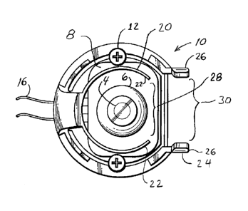
FIG. 1 is a top view of accent lamp 10, according to the present disclosure;
FIG. 2 is a side elevational view of accent lamp 10;
FIG. 3 is a front view of accent lamp 10;
FIG. 4 is a rear view of accent lamp 10;
FIG. 5 is a bottom view of base 2 and PCB 8 of accent lamp 10;
FIG. 6 is a front perspective view of base 2 of accent lamp 10;
FIG. 7 is a front perspective view of accent lamp 10 attached to headlamp 40;
FIG. 8 is an exploded perspective view of components of accent lamp 10, and a
perspective view of headlamp 40;
3
CA 02921025 2016-02-17
FIG. 9 is a partial cut-away perspective view from the rear of headlamp 40
showing light guide 42;
FIG. 10 is a bottom view of headlamp 40 including light guide 42;
FIG. 11 is a sectional view of accent lamp 10 connected to headlamp 40 which
is
latched to reflector 100 on the vehicle chassis; and
FIGs. 12A and 12B is an excerpt from the Prior Art document SAE (Society of
Automotive Engineers) J2560 Issued July 2007.
DETAILED DESCRIPTION INCLUDING BEST MODE OF
A PREFERRED EMBODIMENT
It may be appreciated that the present disclosure is not limited in its
application to
the details of construction and the arrangement of components set forth in the
following
description or illustrated in the drawings. The embodiments herein may be
capable of
being practiced or being carried out in various ways. Also, it may be
appreciated that the
phraseology and terminology used herein is for the purpose of description and
should not
be regarded as limiting as such may be understood by one of skill in the art.
The combination of the automotive headlamp 40 and its associated accent lamp
10 disclosed herein is suitable for use on a motor vehicle, particularly in
the reflector
cavity for the vehicle forward lighting such as the vehicle headlamp or fog
lamp
(collectively be referred to herein as a vehicle headlamp) which is used to
illuminate a
road surface. The type of motor vehicle may include, but is not limited to, a
land vehicle
such as a passenger sedan, a sport utility vehicle, a minivan, a truck (light
or heavy truck)
and a recreational vehicle (e.g., ATV, motorcycle, snowmobile). Alternatively
the motor
vehicle may also include water vehicles (e.g. boats, jet-skis, personal water
craft) and air
vehicles (e.g. planes, helicopters).
4
CA 02921025 2016-02-17
I. The Accent Lamp component
An accent lamp 10 provides an accent or auxiliary illumination to the motor
vehicle. Accent lamp 10 is configured to be arranged adjacent an exterior
surface of
headlamp 40. Accent lamp 10 provides accent illumination from the headlamp
cavity,
particularly supplemental ornamental lighting, which may be understood to be
lighting
provided out of the vehicle's reflector cavity that is alternate to or
different from the
lighting provided out of the reflector cavity at the time of original
manufacture of the
motor vehicle.
Referring to FIGs. 1-6, accent lamp 10 has a solid-state light source which
may
include at least one light-emitting diode ("LED") 4, and may further comprise
a plurality
of LEDs 4a, 4b, 4c. The LEDs 4 are mounted on a surface such as printed
circuit board
("PCB") 8 which contains traces that receive power from electric leads 16.
Electrical
control to an accent lamp is known in pending United States patent application
Serial No.
14/700,435 entitled "Motor Vehicle Accent Lamp and Methods of Use therefor"
(naming
Weiss, Lessard, Holland, and Landcastle) filed April 30, 2015 by one or more
of the
inventors of the present application, and is hereby incorporated by reference
as if fully set
forth herein.
Heat from LEDs 4 is transferred to and otherwise managed by housing 32, which
may be formed of metal such as a die-casting. PCB 8 is received in a pocket
formed in
housing 32. The exterior surface of housing 32 preferably includes a plurality
of heat
sink fins or pins 14 to dissipate heat from LEDs 4.
In particular, of the plurality of LEDs 4a, 4b, 4c, LED 4a can comprise a red
LED, LED 4b can comprise a green LED, and LED 4c can comprise a blue LED. The
three LEDs 4a, b, c can be arranged in a triangle, and the center of the
triangle can
coincide with a longitudinal axis extending through the center of light guide
42 discussed
herein. Within the electromagnetic spectrum, red LED 4a may operate at a
wavelength
(X) in a range of 620 nm to 700 nm, and even more particularly in a range of
620 nm to
645 nm. Green LED 4b may operate at a wavelength (X) in a range of 500 nm to
570 nm,
and more particularly in a range of 520 nm to 550 nm. Blue LED 4c may operate
at a
5
CA 02921025 2016-02-17
frequency in a range of 450 nm to 500 nm, and more particularly in a range of
460 nm to
490 nm. While discrete red, green and blue LED chips can be used, other chip
packages
contain all three dies bonded into one chip; RGBW (white) and RGBA (amber)
chip
combinations can also be used to enhance control. In other embodiments of the
present
disclosure, the accent lamp 10 may be configured to emit achromatic (white)
light, such
as for use as daytime running lights.
With regards to maximum intensity, the maximum light intensity emitted from
the
accent lamp 10 is configured to be lower than the light intensity emitted from
the low
beam or high beam of headlamp 40. For example, a light source 44 for headlamp
40 such
as a an HB4/9006 halogen headlamp bulb is designed to emit about 700 lumens on
low
beam and about 1200 lumens on high beam. In contrast, the maximum light
intensity
emitted from light-emitting device 4 of each accent lamp 10 is configured to
be less than
or equal to 300 lumens. For example, the light intensity emitted from light
source 4 may
range of 5 lumens to 300 lumens, and more particularly in a range of 20 lumens
to 250
lumens, and even more particularly in a range of 40 lumens to 100 lumens.
The LEDs 4 may be arranged as part of a light engine, which may comprise an
LED driver on PCB 8 to which the LEDs 4a, 4b and 4c are mounted as well as the
electrical wiring to provide a signal to those LEDs on color and intensity, as
is known in
the art and not shown. The LED driver can be mounted on a PCB separate from
the PCB
on which the LEDs are mounted, or mounted on the same PCB with the LEDs.
The LEDs 4 emit light extending along principal direction P, preferably in a
Lambertian distribution having maximum intensity perpendicular to PCB 8 and
falling
off with increasing angle away from perpendicular. Referring to FIG. 7, in
assembled
condition, principal direction P is directed similar to axis 0 of headlamp
capsule 44.
LEDs 4 are positioned underneath lens 6, which is preferably a collimating
lens to
promote directing light emitted by accent lamp 10 into light guide 42.
Accent lamp 10 has base 2 which is mounted to housing 32 and secured thereon,
such as by fasteners 12, and acts as a cover to retain PCB 8 and lens 6.
Referring to
FIGs. 5-6 and 8, an underside of base 2 has annular ribs 34 that are received
in a pocket
6
CA 02921025 2016-02-17
in housing 32. Extending upward on resilient post 18 is first retaining member
20 which
is located above mounting surface 8. A second retaining member 24 also extends
from
base 2. Each of first and second retaining members 20, 24 are configured to
attach to
respective spaced-apart portions of headlamp base 60.
First or second retaining member 20, 24 could be an adhesive. First or second
retaining member 20, 24 could be a separate component such as a flexible band,
a hose
clamp, a toggle clamp, or a zip tie or cable tie (such as a cable tie as
generally shown in
U.S. Pat. 5,911,367 (McInerney)), which during assembly is connected to or
around base
2 and headlamp base 60.
Alternatively, and preferably, first and/or second retaining member 20, 24 is
formed integrally with base 2, such as molded of a resilient thermoplastics
material, such
as a nylon or acetal. Preferably first retaining member 20 is a C-shaped first
clamp
resembling a collar formed by two arms 22. Second retaining member 24 extends
from
base 2 at a position closer to PCB 8. Second retaining member 24 is also a
clamp that has
two resilient arms 26. First and second retaining members 20, 24 are
approximately
parallel to each other. The first clamp has two arms 22 that at their free
ends are spaced
from one another to define a first passageway 28 that is configured to receive
the capsule
lead-receiving region 64 of headlamp base 60 to which first clamp 20 attaches.
The
second clamp has two arms 26 that at their free ends are spaced from one
another to
define a second passageway 30 that is configured to latch onto the vehicle
wiring
connector-receiving region 65 of headlamp base 60.
Accent lamp 10 may further comprise a power supply (not shown) to supply
power to accent lamp 10, which may be electrically coupled thereto by
electrical wiring
16. In addition, accent lamp 10 may further comprise a controller (not shown)
electrically coupled to the power supply. Among other things, the controller
may be used
to control the power output emitted from the power supply, particularly based
on input
received from a user of the accent lamp 10. Such a controller may be located
in the
passenger compartment of a motor vehicle, such as located on the instrument
panel.
7
CA 02921025 2016-02-17
The power supply may receive power from a power source, e.g. a car battery,
which is electrically coupled thereto by electrical wiring. The power supply
may further
comprise a housing containing a constant current power supply for exciting the
LED
chips. The output of the power supply to the accent lamp 10 may be controlled
by a
feedback loop which includes a sense resistor, which may be located in the
accent lamp
10, or any other suitable location. In certain embodiments of the present
disclosure, the
controller and/or the power source may be included in the power supply,
particularly
within a housing.
In certain embodiments of the present disclosure, the controller may be a
wireless
controller configured to receive input (control) signals from a wireless
transmitter. The
wireless transmitter may comprise computer programming operable on a micro-
computer, such as may be provided by a radio, laptop computer, a tablet
computer or a
smart (cell) phone. The wireless controller and wireless transmitter may
communicate
wirelessly using Wi-Fi0 technology or Bluetoothe technology or other suitable
wireless
communication technology.
The computer programming may be provided in the form of a computer software
application which operates on the micro-computer. The computer software may
provide
a graphical user interface (GUI) which enables the user to select a color and
intensity of
chromatic (colored) light to be emitted from the accent lamp 10. Software may
run on
the receiving end, receiving from the GUI computer, which in turn commands the
intensity of each color through a constant current driver circuit.
For example, the graphical user interface may enable the user to select a
color
from a display of available colors provided on a color palette which enables
the user to
select a color of the chromatic (colored) light to be emitted from the accent
lamp 10. The
color palette may make use of an RGB color model. The RGB model may be
understood as an additive color model in which red, green, and blue light from
the LEDs
4a, 4b and 4c are combined together in various levels to reproduce a broad
array of
colors. The RGB model may be a true color model which provides, for example,
at least
256 shades of red, green and blue for a total of at least 16 million color
variations.
8
CA 02921025 2016-02-17
The graphical user interface may also enable the user to enter a specific
value for
each of the red, green and blue shades between 0 and 255 as known in the art,
which may
be in addition to or alternatively to the color palette. The graphical user
interface may
also enable the user to enter specific values for HSL (hue-saturation-
lightness) and HSV
(hue-saturation-value), which may be understood as the two most common
cylindrical-
coordinate representations of the points in the RGB color model.
In addition to color, the graphical user interface may also enable the user to
adjust
the output intensity of accent lamp 10 between full intensity and a fraction
of full
intensity. For example, the graphical user interface may enable the user to
adjust the
output intensity of accent lamp 10 based on a percentage of full intensity
ranging from
zero (off) to 100% (full on) in 1% point increments. Use of an 8-bit
controller permits
adjustment close to 1/255 or nearly 0.5% increments. Thus, for example the
graphical
user interface may enable the user to adjust the output intensity of accent
lamp 10 at 10%,
20%, 30%, 40%, 50%, 60%, 70%, 80%, 90% and 100% of output intensity.
The color and intensity of the illumination emitted from the accent lamp 10
may
be derived using pulse width modulation on red LED 4a, green LED 4b and blue
LED 4c
in a manner known in the art.
II. The Automotive Headlamp component
The automotive headlamp 40 is of conventional design and construction except
that a light passageway 45 has been bored through lamp base 60.
Construction details of a conventional headlamp 40 are shown in each of U.S.
Pats. 7,008,096 (Coushaine); 7,261,451 (Coushaine); 6,080,019 (Coushaine);
6,270,235
(Coushaine); 6,254,252 (Coushaine); 5,696,424 (Coushaine); and US Pat. Pub.
US2010/0213815 (Aghamehdi), which are each incorporated hereby in their
entirety as if
fully set forth herein.
Automotive headlamp 40 is shown in FIGs. 7-11. Headlamp 40 has lamp capsule
44 which contains a light source 46, such as a tungsten halogen filament
capsule.
Headlamp 40 generally provides achromatic ("white") light. Achromatic light is
9
CA 02921025 2016-02-17
understood to be light which is color neutral to the naked human eye. Capsule
electric
leads 48, 50 extend through press seal end 52 to power the filament. Lamp
capsule 44 is
arranged on headlamp base 60 with its capsule major longitudinal axis 0
extending
perpendicularly away from upper surface 61 of headlamp base 60. Retainer 54
grasps
press seal 52 in a known manner. Retainer 54 may also include brackets or legs
58,
which may be formed of sheet metal. Retainer 54 connects lamp capsule 44 to
headlamp
base 60. Brackets 58 have slots formed therein and/or spaces between adjacent
brackets
58 that define apertures 56. Apertures 56 form light exit regions for light
emitted by
accent lamp 10 when it is coupled to headlamp 40.
Headlamp base 60 has upper surface 61 and a lower surface 63. Lower surface 63
is formed on an outer, peripheral surface of headlamp base 60. Lower surface
63 is
preferably a bottom surface of headlamp base 60.
Referring to FIGs. 8, 9 and 11, headlamp base 60 has capsule lead-receiving
region 64 into which electric leads 48, 50 extend from capsule 44. Headlamp
base 60
further has contacts 68, 68 which are in vehicle wiring connector-receiving
region 65.
Contacts 68, 68 are electrically connected to capsule leads 48, 50, as seen in
FIG. 9, such
as by welding, in order to provide electrical connection to the wiring harness
which is
part of the motor vehicle. Referring to FIGs. 7-9, capsule lead-receiving
region 64 is
generally transverse to vehicle wiring connector-receiving region 65, such
that headlamp
base 60 is generally L-shaped. The capsule electric leads 48, 50, at least
within lead-
receiving region 64, are approximately transverse to electrical contacts 68.
Referring to FIGs. 12A, 12B there is shown an excerpt from an SAE (Society of
Automotive Engineers) technical specification. SAE Document J2560 at pages 41-
56
(issued July 2007) is incorporated hereby in its entirety as if fully set
forth herein. An
excerpt shown in FIGs. 12A, 12B contains specifications of a 9005 bulb,
depicting a
suitable L-shaped headlamp base 60, which fits within the spatial envelope of
bulbs
designated as SAE-9005, SAE-9006, SAE-9145, SAE-9140, SAE-9155, SAE-9040,
SAE-9045, SAE-9055, EC-HB3, EC-HB4, or EC¨HB10.
CA 02921025 2016-02-17
Referring to FIGs. 7 and 11, headlamp base 60 includes locking tabs 70 to make
connection to reflector 100, as is known in the art by linear insertion
followed by a turn
of headlamp 40 about capsule axis 0.
Referring to FIGs. 7, 9 and 11, headlamp base 60 can have circumferential
groove
62 which helps receive and seat collar-like clip 20 of accent lamp 10.
Referring to FIGs. 9 and 11, headlamp base 60 defines, on an interior region
thereof, a cavity 47 underneath lamp capsule 44 which defines a light
passageway 45.
Light passageway 45 extends from an aperture in outermost peripheral surface
63, which
is preferably a bottom surface, to upper surface 61. Light passageway 45
adjacent to
peripheral surface 63 forms a light entrance window at peripheral surface 63,
so that light
which enters from a region external of headlamp 40, i.e. from accent lamp 10,
is directed
toward an underside of press seal 52 and/or to light exit apertures 56.
Light passageway 45 could be an open bore, which might be acceptable in dry
climates, but in humid conditions that could permit entry of moisture into the
vehicle
headlamp reflector cavity which could deposit on reflector 100. In order to
better seal the
vehicle reflector cavity, and to guide the light from accent lamp 10, a light
guide 42 is
positioned in light passageway 45. Light guide 42 is optically transmissive to
wavelengths of light from solid state light source 4. Light guide 42 can be
made of a
plastics material, a glass such as quartz glass, or optical grade silicone. If
light guide 42
is made of a plastics or glass, it is helpful to apply silicone sealant
between light guide 42
in light passageway 45 to inhibit moisture entry. Light guide 42 is preferably
a solid rod,
preferably cylindrical. Light guide 42 closes off light passageway 45 at the
light entrance
window at peripheral surface 63, but does not need to physically occupy an
entire length
of light passageway 45. Light guide 42 is aligned with central axis 0 of lamp
capsule 44.
Light guide 42 extends into cavity 47 but does not need to extend up to the
height of
upper surface 61 of headlamp base 60, but rather its length can end below it;
this can
encourage injecting light not only into press seal region 52 but also to
reflect off of press
seal 52 and the sheet metal of which retainer 54 and bracket 58 are formed.
Referring to
FIG. 11, capsule electric leads 48, 50 are spaced laterally from a path light
emitted from
CA 02921025 2016-02-17
accent lamp 10 would traverse through light passageway 45, or light guide 42,
to avoid
interfering with the light path.
Referring to FIG. 10-11, light guide 42 at light entrance window is preferably
flat,
which promotes good optical coupling to an upper surface of lens 6 when accent
lamp 10
is coupled to headlamp 40. Optionally, light guide 42 is flush with peripheral
surface 63.
Light passageway 45 is preferably straight, and extends from bottom surface 63
to
direct light toward upper surface 61. If light passageway 45 were not
straight, for
example if external light entered a light entrance window on a lateral side
surface of
headlamp base 60 near groove 62, then manipulation of light with a reflector
or curved
light guide would route the light from accent lamp 10 toward the exit of light
passageway
45 near upper surface 61 so that the light from accent lamp 10 would strike
near an
underside of press seal 52 and exit at light exit regions 56 in retainer 58.
Such an
arrangement could be used to couple accent lamp 10 to an automotive lamp
having a
straight, rather than L-shaped, base, such as for example with an automotive
lamp of the
type marketed under the SAE designation 9004 (ECE HB1), an example of which is
depicted at Fig. 7 in Coushaine Pat. 6,080,019, since the vehicle wiring
harness is
plugged onto the lower end below and opposite the press seal region.
III. Operative association
Referring to FIGs. 1-7, first and second retaining members 20, 24 are
approximately parallel to each other. The first clamp has two arms 22 that at
their free
ends are spaced from one another to define a first passageway 28 that is
configured to
receive an exterior surface of the capsule lead-receiving region 64 of
headlamp base 60 to
which first clamp 20 attaches. The second clamp has two arms 26 that at their
free ends
are spaced from one another to define a second passageway 30 that is
configured to latch
onto the vehicle wiring connector-receiving region 65 of headlamp base 60.
Referring in particular to FIG. 2, resilient post 18 permits the collar formed
at first
retainer clamp 20 to pivot slightly, in the manner of a cantilever beam,
approximately
about the region where post 18 joins base 2, towards and away from PCB 8. In
an
12
CA 02921025 2016-02-17
assembled condition of FIG. 7, second retaining member 24 locks onto the
connector-
coupling region 65 of headlamp base 60, then the action of coupling first
retaining clamp
20 around groove 62 causes post 18 and first retaining member 20 to be
deflected slightly
from its neutral position, thus urging accent lamp 10 and headlamp 40 into
closer
connection. This results in promoting orientation of the parts and biasing an
upper
surface of lens 6 and a light entrance window of light guide 42 towards one
another,
preferably into flush mating contact.
First and second passageways 28, 30 for introduction of headlamp 40 are open
both from a lateral side, as shown in top view of FIG. 1, and open in a
direction
extending vertically away from PCB 8, as shown in side view of FIG. 2.
Referring in particular to FIGs. 7-8, to effect assembly, accent lamp 10 is
easily,
by application of moderate finger force, tilted slightly relative to headlamp
40 to hook
arms 26 of second passageway opening 30 over an upper surface of wiring
connector-
receiving region 65 of headlamp 40, and then slid in an approximately
translational
motion perpendicular to capsule major axis 0, whereupon some slight resistance
is
encountered at first passageway opening 28 due to a separation distance
between arms
22, 22 being chosen smaller than an outer surface of capsule lead-receiving
region 64
such as diameter of groove 62, and overcoming this resistance allows first
retaining
member 20 to clamp to groove 62. This positioning can also bias resilient post
18 to
promote optical coupling of light source 4 to light guide 42.
Alternatively, accent lamp 10 can be introduced onto headlamp 40 in a
direction
generally parallel capsule major axis 0 by tilting peripheral surface 63 to
introduce a
region of headlamp base 60 adjacent light guide 42 down between arms 22 of
first
retainer member 20 to pass through first passageway 28 and then translating
headlamp 40
downward so that wiring connector-receiving region 65 prises open resilient
arms 26,
also resulting in the assembled condition of FIGs. 7, 11 and promoting optical
coupling.
Due to the simple assembly direction, accent lamp 10 can be mounted to
headlamp 40 either before or after headlamp 40 is mounted into vehicle
headlight cavity
by mating it with tabs 70 to vehicle-mounted reflector 100 through an opening
accessed
13
CA 02921025 2016-02-17
via the vehicle engine compartment. Accent lamp 10 is, when desired for
replacement of
accent lamp 10 or of headlamp 40, selectively readily detachable from headlamp
40, such
as for repair, servicing or relamping.
While a preferred embodiment of the present disclosure has been described, it
should be understood that various changes, adaptations and modifications can
be made
therein without departing from the spirit of the disclosure and the scope of
the appended
claims. The scope of the disclosure should, therefore, be determined not with
reference
to the above description, but instead should be determined with reference to
the appended
claims along with their full scope of equivalents. Furthermore, it should be
understood
that the appended claims do not necessarily comprise the broadest scope of the
disclosure
which the applicant is entitled to claim, or the only manner in which the
disclosure may
be claimed, or that all recited features are necessary.
14