Note: Descriptions are shown in the official language in which they were submitted.
CA 02921169 2016-02-19
Attorney Docket No. 617/3TM-000277-US
CLAMPING DEVICE WITH REMOVABLE HANDLES
CROSS-REFERENCE TO RELATED APPLICATION
[0001] This application claims the benefit of U.S. Provisional Application
No.
62/120,538, filed on February 25, 2015. The entire disclosure of the above
application
is incorporated herein by reference.
FIELD
[0002] The present disclosure relates to clamping and, more particularly,
to a
clamping device with a removable handle.
BACKGROUND
[0003] When clamping workpieces with manual clamps, ordinarily the clamps
have handles that extend beyond the workpiece. The user is required to be
present
around the clamped workpiece conducting other operations. Since the handles
project
beyond the workpiece, the handles are constantly in the way of the user as he
moves
about the workpiece. Ordinarily, the handles are bumped or nudged requiring
realignment of the clamping device. In some instances, the clamp may be bumped
so
that it is removed from the workpiece causing additional work to be conducted
onto the
workpiece. Additionally, the overhang of the handles adds additional weight
which
increases the moment/torque on the workpiece. Thus, it is possible to cause
distortion
on thin workpiece structures.
1
CA 02921169 2016-02-19
Attorney Docket No, 6178TM-000277-US
[0004] However, the handles are an important part of the clamp. The handles
provide leverage to open the clamp so that the clamp may apply a greater force
onto
the workpiece. The longer the handles, the less force required to open the
clamps and
generally the larger the force applied by the clamps onto the workpiece.
[0005] Accordingly, while handled clamps serve a vital purpose, it is
desirable to
move the handles out of the way so that the handles are not bumped, contacted,
or
otherwise interfered with by the user while the user is conducting work around
the
workpiece.
[0006] U.S. Patent No. 8,740,208, assigned to the assignee of the present
disclosure, provides a clamping system with a removable handle. The handle
enables
the clamp to be applied to the workpiece. The handle is then removed from the
clamp
so that the handles do not interfere with the user or other materials during
manipulation of the workpiece. While the patent works satisfactorily,
designers are
always striving to improve the art.
SUMMARY
[0007] According to a first aspect of the disclosure, a clamping device
with a
removable handle comprises a pair of clamping arms. A pivot device is coupled
with
the pair of clamping arms. The pivot device includes a clamp bushing linked
with each
of the clamping arms of the pair of clamping arms. The pivoting device moves
the pair
of arms between an opened and a clamped position. A removable handle is
coupled
with the clamp bushing. The removable handle includes a release mechanism to
2
=
CA 02921169 2016-02-19
Attorney Docket No. 6178TM-000277-US
activate the pivot mechanism. During activation, the clamping arms are moved
between an opened and clamped position.
[0008] The bushing further includes a polygonal inner wall to receive the
handle.
The handle includes a spigot with a ball lock for engaging and disengaging the
pivot
mechanism. The spigot has a polygonal portion in the area of the ball lock to
mate with
the polygonal portion of the pivot mechanism. The release mechanism includes a
pivot
lever coupled with a sliding bushing. The sliding bushing engages the pivot
mechanism
clamp bushing. The pivot lever is moved between a first and second position.
This
moves the clamp and sliding bushings between the first and second position
which, in
turn, moves the arms between an open and clamped position.
[0009] Further areas of applicability will become apparent from the
description
provided herein. The description and specific examples in this summary are
intended for
purposes of illustration only and are not intended to limit the scope of the
present
disclosure.
DRAWINGS
[0010] The drawings described herein are for illustrative purposes only of
selected embodiments and not all possible implementations, and are not
intended to
limit the scope of the present disclosure.
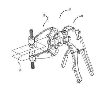
[0011] FIG. 1 is a perspective view of the clamping device.
[0012] FIG. 2 is an elevation view of the clamping device of FIG. 1
3
CA 02921169 2016-02-19
Attorney Docket No. 6178TM-000277-US
[0013] FIG. 3 is a perspective view of the clamping device with the handle
=
removed.
[0014] FIG. 4 is an exploded perspective view of the clamp arms.
[0015] FIG. 5 is an exploded perspective view of the removable handle.
[0016] FIG. 6 is a cross-section view of FIG. 1.
[0017] FIG. 7 is a cross-section view like FIG. 6 in an intermediate
position.
[0018] FIG. 8 is a cross-section view of FIG. 1 in an open position.
[0019] FIG. 9 is a view like FIG. 8 with a handle in a disengaged position.
DETAILED DESCRIPTION
[0020] Example embodiments will now be described more fully with reference
to
the accompanying drawings.
[0021] Turning to the figures, a clamping device is illustrated and
designated
with the reference numeral 10. The clamping device 10 includes a clamp 12 and
a
removable handle assembly 14. The clamp 12 is illustrated clamped to a
workpiece 16.
FIG. 3 illustrates the handle assembly 14 removed from the clamp 12. FIGS. 4
and 5
illustrate exploded views of the clamp 12 and handle assembly 14.
[0022] The clamp 12 includes a pair of arms 18. The arms 18 are joined at
one
end by a pivot mechanism 20. The arms 18 are identical and have a threaded
collar 22
to receive a set screw 24. The other end of the arm includes a clevis 26 to
attach the
arms to a fulcrum member 28. The arms 18 include apertures that receive pins
30 that
4
CA 02921169 2016-02-19
Attorney Docket No. 6178TM-000277-US
pass through apertures in the fulcrum member 28 to enable the arms 18 to pivot
with
respect to the fulcrum member 28 from an open to a closed position.
[0023] The
fulcrum member 28 includes a body 32 with a pair of arms 34. The
arms 34 include apertures that receive the pins 30. The body 32 has a hollow
configuration. The interior surface 35 of the cylinder has a polygonal
configuration and
is shown as a hexagonal configuration. This enables the removable handle
assembly 14
to be positioned at different angles with respect to the clamp 12.
Additionally, the
interior surface 35 includes a ball groove 36 that receives balls from the
handle
assembly ball lock 104 to lock the handle assembly 14 with the clamp 12.
[0024] The
arms 18 include a clevis end 38 that includes an aperture to receive
pins 40. Links 42 are secured to the arms 18 via the pins 40. The links 42 are
coupled
with the clamp bushing 44. The clamp bushing 44 has a hollow right cylinder
body 46
that terminates at a flange 48. The clamp bushing 44 also includes a pair of
arms 50
that include apertures to receive pins 52. The pins 52 also couple with the
links 42 to
secure the clamp bushing 44 with the arms 18.
[0025] The
handle assembly 14 includes a release mechanism 60 that, when
coupled with the clamp 12, moves the clamp 12 between its open and clamped
position. The handle assembly 14 includes an engagement mechanism 62 to engage
and disengage the handle assembly 14 with the clamp 12 in a locked and removed
position.
[0026] The
handle assembly 14 includes a grip 64. The grip 64 includes a slot 66
that enables a trigger member 68 of the engagement mechanism 62 to pass
through
CA 02921169 2016-02-19
Attorney Docket No. 6178TM-000277-US
the grip 64. Also, the grip 64 includes a housing portion 70 that includes
apertures for
passage of the release mechanism 60 and engagement mechanism 62.
[0027] The release mechanism 60 includes a squeeze lever 72 pivotably
coupled,
via pin 75, with the grip housing portion 70. The squeeze lever 72 moves
between a
first and second position. It is illustrated in a closed position in FIGS. 1
and 3 and in
normally open position in FIG. 2. A spring 73 keeps the squeeze lever 72 in
its normally
open position. The squeeze lever 72 is coupled with a slide bushing 74 via
links 76.
The links 76 are pinned to the squeeze lever 72 as well as the slide bushing
74. The
slide bushing 74 includes a body 77 as well as a ball lock mechanism 78. The
ball lock
mechanism 78 includes a pair of ball lock expanders 80 that are biased by
springs 82
through apertures 84 in the body 77. The ball lock expanders 80 work with the
balls 96
to lock and unlock the sliding bushing 74 with the clamp bushing 44 about the
flange
48.
[0028] A release lever 90 is pivotally secured, via a pin 97, in the
squeeze lever
72. The release lever 90 includes a cam portion 94 that abuts against the grip
64. As
the release lever 90 is pushed forward, the cam portion 94 pushes against the
grip 64
moving the squeeze lever 72 away from the grip 64. The spring 73 then moves
the
squeeze lever 72 into its open position to move the clamp 12 to an open
position as
seen in FIG. 2.
[0029] The engagement mechanism 62 includes trigger member 68 pivoted via
pin 92 on the grip 64. The end of the trigger member 68 includes a slot 69 to
secure
with a plunger 98 via a pin 99. The plunger 98 moves within a spigot 100 that
extends
6
CA 02921169 2016-02-19
Attorney Docket No. 6178TM-000277-US
from the handle assembly 14. The spigot 100 includes a polygonal end 102 that
includes the ball lock mechanism 104. The polygonal end 102 mates with the
polygonal
interior 35 of the body 32. The spigot 100 also includes a ball lock expander
106 that is
biased by spring 108. The plunger 98 is biased by spring 110 to move the
trigger
member 68 between a first and second position. Also, the plunger 98 includes a
pin
112 that actuate the ball expanders 80.
[0030] To connect and disconnect the handle assembly 14 with the clamp 12,
the
trigger member 68 is pulled towards the grip 64. As this occurs, the plunger
98 moves
in the spigot 100. As this occurs, the pin 112 contact the ball lock expanders
80 and
the end of the plunger 98 contacts ball lock expander 106. As this happens,
the
grooves 114, 116 of the ball lock expanders 80, 106 are aligned with the balls
86, 96
enabling the balls 86, 96 to move into the grooves 114, 116. Thus, the balls
86, 96 of
the ball lock mechanisms 78, 104 move into the grooves 114, 116. This enables
the
handle assembly 14 to be inserted into the pivot mechanism clamp bushing 44 or
to be
removed from it.
[0031] Once the handle assembly 14 is coupled with the clamp bushing 44,
the
trigger member 68 is released. The trigger member 68 moves towards the housing
portion 70 of the grip 64. This enables the spring 110 to bias the plunger 98
away from
the clamp 12. As this occurs, the cylinder portions 118, 120 of the ball lock
expanders
80, 106 come into contact with the balls 86, 96 locking the ball 96 with the
flange 48
and the ball 86 in the groove 36, respectively.
7
CA 02921169 2016-02-19
1
Attorney Docket No. 6178TM-000277-US
[0032] Thus, the clamp 12 and handle assembly 14 are connected with one
another. With the squeeze lever 72 in an open position, as in FIG. 2, the
squeeze lever
72 is moved towards the grip 64. As this occurs, the squeeze lever 72 pivots
about
pivot pin 75 which moves the linkage pins 76 which, in turn, moves the slide
bushing 74
towards the clamp 12. As the slide bushing 74 moves towards the clamp 12, the
clamp
bushing 44 moves towards the fulcrum member 28. As this occurs, the clamp arms
18
move into a clamping position. The links 42 are in an overcenter position
locking the
clamping arms 18 in position.
[0033] To open the clamps 12, the release lever 90 is moved towards the
grip 64.
As this occurs, the cam portion 94 cams against the grip 64 to move the
squeeze lever
72 away from the grip 64. The spring 73 then biases the squeeze lever 72 to
its open
position. As the squeeze lever 72 moves to an open position, the links 76 pull
on the
slide bushing 74. The slide bushing 74 is secured with the flange 48 of the
clamp
bushing 44, via the ball locks 86. This movement moves the clamp bushing 44
along
spigot 100 away from the fulcrum member 28 which, in turn, moves the arms 18
into
an open position. If desired, the clamp 12 can be removed from the handle
assembly
14 by activating the trigger member 68 as explained above to disengage the
handle
assembly 14 from the clamp 12.
[0034] The foregoing description of the embodiments has been provided for
purposes of illustration and description. It is not intended to be exhaustive
or to limit
the disclosure. Individual elements or features of a particular embodiment are
generally
not limited to that particular embodiment, but, where applicable, are
interchangeable
8
CA 02921169 2016-02-19
Attorney Docket No. 6178TM-000277-US
and can be used in a selected embodiment, even if not specifically shown or
described.
The same may also be varied in many ways. Such variations are not to be
regarded as
a departure from the disclosure, and all such modifications are intended to be
included
within the scope of the disclosure.
9