Note: Descriptions are shown in the official language in which they were submitted.
CA 02921217 2016-02-11
WO 2015/023739 PCT/US2014/050869
SYSTEMS AND METHODS FOR
SUPPORTING BOLLARDS
Cross-Reference to Related Application(s)
This application claims priority to co-pending U.S. Provisional Application
serial number 61/865,413, filed August 13, 2013, which is hereby incorporated
by
reference herein in its entirety.
Background
Bollards are short vertical posts that are often used to obstruct the passage
of
motor vehicles. In conventional systems, each bollard is attached to a
horizontal
steel beam that is embedded in concrete. In systems that comprise multiple
bollards,
multiple steel beams are used (one for each bollard), which are typically
parallel to
each other. The bollards are attached to the front ends, i.e., the ends that
face
vehicle traffic, of the beams. Steel rebar mats are typically positioned above
and
below the beams to reinforce the concrete and limit movement of the beams
should
a vehicle impact one or more of the bollards.
While the above-described systems function adequately well, these systems
are inefficient. When a vehicle impacts a bollard, a moment is applied to the
bollard
that, if it were not adequately supported, would knock it over. The beam and
the
1
CA 02921217 2016-02-11
WO 2015/023739 PCT/US2014/050869
rebar mat that lies below the beam are designed to oppose this moment. In
order to
achieve this, the beam must be relatively long and thick, and therefore
requires a
large amount of steel to construct. The rebar mats that are provided above and
below the beams only add to the amount of steel that is required to fabricate
the
system. The large amount of steel that is required in such systems
unnecessarily
increases the costs of the systems.
From the above discussion, it can be appreciated that it would be desirable to
have systems and methods for supporting bollards that require less steel.
Brief Description of the Drawings
The present disclosure may be better understood with reference to the
following figures. Matching reference numerals designate corresponding parts
throughout the figures, which are not necessarily drawn to scale.
Fig. 1A is a perspective view of a first embodiment of a bollard system.
Fig. 1B is a schematic end view of support beams and a woven reinforcement
bar of the system of Fig. 1A.
Fig. 1C is a schematic end view of the woven reinforcement bar shown in Fig.
1B.
Fig. 2A is a perspective view of a second embodiment of a bollard system.
Fig. 2B is a schematic end view of support beams and a woven reinforcement
bar of the system of Fig. 2A.
Fig. 20 is a schematic end view of the woven reinforcement bar shown in Fig.
2B.
Fig. 3A is a perspective view of a third embodiment of a bollard system.
2
CA 02921217 2016-02-11
WO 2015/023739 PCT/US2014/050869
Fig. 3B is a schematic end view of support beams and woven reinforcement
bars of the system of Fig. 3A.
Fig. 30 is a schematic end view of the woven reinforcement bars shown in
Fig. 3B.
Fig. 4A is a perspective view of a fourth embodiment of a bollard system.
Fig. 4B is a schematic end view of support beams and woven reinforcement
bars of the system of Fig. 4A.
Fig. 40 is a schematic end view of a woven reinforcement bar shown in Fig.
4B.
Fig. 5A is a perspective view of a fifth embodiment of a bollard system.
Fig. 5B is a schematic end view of support beams and woven reinforcement
bars of the system of Fig. 5A.
Fig. 50 is a schematic end view of a woven reinforcement bar shown in Fig.
5B.
Fig. 6A is a perspective view of a sixth embodiment of a bollard system.
Fig. 6B is a schematic end view of support beams and woven reinforcement
bars of the system of Fig. 6A.
Fig. 60 is a schematic end view of a woven reinforcement bar shown in Fig.
6B.
Fig. 7A is a perspective view of a seventh embodiment of a bollard system.
Fig. 7B is a schematic end view of support beams and woven reinforcement
bars of the system of Fig. 7A.
Fig. 70 is a schematic end view of a woven reinforcement bar shown in Fig.
7B.
3
CA 02921217 2016-02-11
WO 2015/023739 PCT/US2014/050869
Detailed Description
As described above, it would be desirable to have systems and methods for
supporting bollards that require less steel than conventional systems.
Disclosed
herein are examples of such systems and methods. In some embodiments, bollards
are attached near the centers of support beams of the system instead of the
front
ends of the beams. When a bollard is struck by an impacting vehicle, the
moment
applied to its support beam is resisted by both the front (compression) end
and the
rear (tension) end of the beam. Approximately half of the moment in the
bollard will
be carried in each direction and, therefore, the peak load on the beam is cut
in half.
Because of this, the beam need not be as robust and therefore can be made from
less material (e.g., steel). In some embodiments, the support beams are
reinforced
with reinforcing bars that are woven between the beams. The advantage of the
woven configuration is that it provides a positive reaction force that resists
motion of
each adjacent support beam whether the beam is pushed upward or downward.
In the following disclosure, various specific embodiments are described. It is
to be understood that those embodiments are example implementations of the
disclosed inventions and that alternative embodiments are possible. All such
embodiments are intended to fall within the scope of this disclosure.
As described above, bollard systems disclosed herein generally include
bollards that are attached near the centers of support beams that are embedded
in
an appropriate foundation material, such as concrete. Also embedded in the
material
are one or more reinforcing bars that are woven between the support beams.
Described below are multiple embodiments of bollard systems that comprise
these
general features.
4
CA 02921217 2016-02-11
WO 2015/023739 PCT/US2014/050869
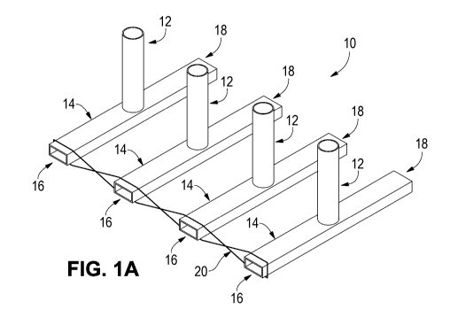
Fig. 1A illustrates a first bollard system 10. As indicated in this figure,
the
system 10 includes multiple bollards 12. More particularly, the illustrated
system 10
includes four bollards 12. While four bollards 12 are shown, if will be
appreciated that
the system 10 can include a greater or lesser number of bollards. In some
embodiments, each bollard 12 comprises a relatively short elongated vertical
member that is designed to withstand the forces associated with an impact from
a
motor vehicle. By way of example, the bollards 12 can comprise steel pipes or
tubes
that may or may not be filled with concrete.
Irrespective of its construction, each bollard is attached, for example,
welded,
to a single support beam 14 near its center (i.e., approximately halfway along
its
length). Because there are four bollards 12 in the illustrated example, there
are four
support beams 14 that together form part of the foundation of the bollard
system 10.
In some embodiments, each support beam 14 is a hollow steel beam having a
front
end 16, a rear end 18, and a rectangular cross-section.
As mentioned above, positioning the bollards 12 near the centers of the
support beams 14 enables the support beams to resist a moment applied to the
bollard using both the front (compression) end and the rear (tension) end of
the
beam. Therefore, approximately half of the moment in the bollard will be
carried in
each direction along the beam 14 and the peak load on the beam is cut in half.
Because of this, the support beams 14 can be made from less material and at
less
expense.
It is further noted that rotation of the bollard 12 due to vehicular impact
will
raise the front end 16 of its associated support beam 14. If the bollard 12
rotates as
much as 30 degrees and the bollard and support beam 14 do not form a plastic
hinge, the front end 16 of the beam may be raised several feet out of the
ground.
CA 02921217 2016-02-11
WO 2015/023739 PCT/US2014/050869
Because the impacting vehicle will be positioned over the support tube 14 at
the
beginning of the impact, the front end 16 of the raised support beam will
likely be
snagged by the vehicle, which will deliver high resistance forces without any
significant bending load in the beam. In some embodiments, the front ends 16
of the
support beams 14 can be optimized to increase the snagging potential and
maximize
load carrying capacity. For example, the top edges of the front ends 16 can be
stiffened and sharpened in order to reduce the size of the snag point needed
to
engage the beam.
Woven between at least the front ends 16 of the support beams 14 is a
reinforcing bar 20. Notably, a similar reinforcing bar 20 is also woven
between the
rear ends 18 of the support beams 14. The reinforcing bar 20 is described
herein as
being "woven" between the beams 14 because it alternately passes over and
under
adjacent beams in a first direction generally perpendicular and then under and
over
the same beams in a second direction opposite to the first direction so as to
tie the
beams together in similar manner to the way in which warp yarns tie together
weft
yarns in a woven textile. As shown in Figs. 1B and 10, the repeated passing
over
and under the beams 14 in the two directions creates multiple crossover points
22 at
which the reinforcing bar crosses over itself and open lobes 24 between the
crossover points in which a support beam 14 can be secured. This configuration
of
the reinforcing bar 20 provides a positive reaction force that resists motion
of the
beams 14 whether they are pushed up or down. This enables the bollards 12 to
be
moved from the front ends of the support beams 14 to the centers of the beams,
as
illustrated in Fig. 1A.
Fig. 1B schematically illustrates the weaving of the reinforcing bar 20
through
the support beams 14. In some embodiments, the reinforcing bar 20 is made of
steel
6
CA 02921217 2016-02-11
WO 2015/023739 PCT/US2014/050869
rebar. In the example of Fig. 1, the reinforcing bar 20 comprises a single,
endless
bar that forms a continuous woven loop that wraps around the beams 14. Fig. 10
shows the reinforcing bar 20 without the presence of the beams 14.
During construction of the bollard system 10, the support beams 14 and their
associated bollards 12 can be positioned at the installation site in the
desired
locations in an orientation similar to that shown in Fig. 1A. A reinforcing
bar 20 can
be passed over at least the front ends 16 of the beams 14 and potentially the
rear
ends 18 of the beams. Once the reinforcing bar(s) 20 is in place, concrete can
be
poured over the beams 14 and the reinforcing bar(s) 20.
Figs. 2-7 illustrate alternative bollard systems. In each of these systems,
the
bollards and the support beams have the same reference numerals and can be
assumed to have similar configurations to those described above in relation to
Fig. 1.
The primary differences between each of the embodiments is the reinforcing
bars
that are used to reinforce the systems. Therefore, the discussions of Figs. 2-
7 that
follow focus on the configurations of the reinforcing bars.
Turning to Fig. 2A, a bollard system 30 includes bollards 12 that are attached
near the centers of support beams 14. Woven between at least the front ends 16
of
the beams 14 is a reinforcing bar 32. The reinforcing bar 32 can have a
construction
similar to that of the reinforcing bar 20 shown in Fig. 1. Therefore, the
reinforcing bar
can be made of steel rebar. In the embodiment of Fig. 2, however, the
reinforcing bar
32 is not endless and therefore has free ends 34 and 36. In the illustrated
example,
the free ends 34, 36 form hooks that wrap around one of the beams 14 (the
leftmost
beam in Figs. 2A and 2B). As shown most clearly in Figs. 2B and 20, the
lengths of
the reinforcing bar 32 forming these hooks form an overlapping region in which
the
lengths run parallel to each other. This overlap provides resistance to
tensile forces
7
CA 02921217 2016-02-11
WO 2015/023739 PCT/US2014/050869
in the circumstance of a vehicle impacting one of the bollards 14. The amount
of
overlap may vary depending upon the application. As before, the weaving of the
reinforcing bar 32 between the breams 14 creates multiple crossover points 38
between which are open lobes 40 in which the beams 14 can be secured.
Referring next to Fig. 3A, a bollard system 50 includes bollards 12 that are
attached near the centers of support beams 14. Woven between at least the
front
ends 16 of the beams 14 are two reinforcing bars 52 and 54. The reinforcing
bars 52,
54 can each have a construction similar to that of the reinforcing bar 20
shown in
Fig. 1. As is shown most clearly in Fig. 30, however, each reinforcing bar 52,
54 has
a generally sinusoidal shape so that, when the bars are inverted relative to
each
other as indicated in Fig. 30, they together form a weaving pattern similar to
that
formed by the single reinforcing bars 20 and 32 of Figs. 1 and 2 (see Fig.
3B).
Described another way, if both bars 52, 54 are considered to trace the general
shape
of a sine wave, the two bars can be oriented such that the waves are 180 out
of
phase with each other. As is apparent from Fig. 3B, this results multiple
crossover
points 56 between which are open lobes 58 in which the support beam 14 can be
secured.
The first reinforcing bar 52 has first and second free ends 60 and 62,
respectively, and the second reinforcing bar 54 has first and second free ends
64
and 66, respectively. In similar manner to the free ends 34, 36 of the
embodiment of
Fig. 2, the first free ends 60, 64 of the bars 52, 54 form hooks that wrap
around one
of the beams 14 (the leftmost beam in Figs. 3A and 3B) and create an
overlapping
region in which the ends run parallel to each other. In addition, the second
free ends
62, 66 of the bars 52, 54 form hooks that wrap around another of the beams 14
(the
rightmost beam in Figs. 3A and 3B) and create an overlapping region in which
the
8
CA 02921217 2016-02-11
WO 2015/023739 PCT/US2014/050869
ends run parallel to each other. As before, the overlapping regions provide
resistance to tensile forces.
With reference next to Fig. 4A, a bollard system 70 includes bollards 12 that
are attached near the centers of support beams 14. Woven between at least the
front ends 16 of the beams 14 are multiple reinforcing bars 72. More
particularly,
there are three reinforcing bars 72 woven between the beams 14 because there
are
four such beams to be reinforced. The reinforcing bars 72 can each have a
construction similar to that of the reinforcing bar 20 shown in Fig. 1. Like
the
reinforcing bar 20, the reinforcing bars 72 each comprise an endless bar that
can be
passed over the beams 14. However, unlike the reinforcing bar 20, the
reinforcing
bars 72 are each only configured to wrap around two adjacent support beams 14.
As
is illustrated most clearly in Fig. 40, each reinforcing bar 72 forms a single
crossover
point 74 so as to form and endless curve having two lobes 76. This curve can
be
described as a "figure-8" shape. Although the reinforcing bars 72 do not weave
individually between each of the beams as in previously described embodiments,
the
same result occurs because, as shown in Fig. 4A, the reinforcing bars 72
overlap
each other. More particularly, the lobes 76 of adjacent reinforcing bars 72
overlap
multiple beams 14 and each other across the foundation. As can be appreciated
from Fig. 4A, in order to achieve this overlap, each reinforcing bar 72 can be
angled
relative to the support beams 14 (i.e., so they are not exactly perpendicular
to the
beams) to make space for two lobes 76 on individual beams.
Referring next to Fig. 5A, a bollard system 80 includes bollards 12 that are
attached near the centers of support beams 14. Woven between at least the
front
ends 16 of the beams 14 are multiple reinforcing bars 82. More particularly,
there are
three reinforcing bars 82 because there are four support beams 14 to be
reinforced.
9
CA 02921217 2016-02-11
WO 2015/023739 PCT/US2014/050869
The reinforcing bars 82 share similarities with both the reinforcing bar 32 of
Fig. 2
and the reinforcing bars 72 of Fig. 4. In particular, the reinforcing bars 82
each have
free ends 88 and 90 that form hooks that wrap around a beam 14 (see Fig. 5B)
like
the reinforcing bar 32. In addition, the reinforcing bars 82 each form a
"figure-8
shape" having a single crossover point 92 and two lobes 94 (see Fig. 50) like
the
reinforcing bars 72. As can be appreciated from Fig. 5A, in order to achieve
this
overlap, each reinforcing bar 82 is angled relative to the support beams 14 to
make
space for two lobes 94 on individual beams.
Turning to Fig. 6, a bollard system 100 includes bollards 12 that are attached
near the centers of support beams 14. Woven between at least the front ends 16
of
the beams 14 are multiple pairs of reinforcing bars 102 and 104, three pairs
being
provided reinforce tie the four support beams. Individually, each reinforcing
bar 102,
104 forms an S-shape, which can be seen most clearly in Fig. 60. However, when
the reinforcing bars 102, 104 are inverted relative to each other as in Fig.
40 and
paired together as in Fig. 6B, they each form a figure-8 shape having a single
crossover point 106 and two lobes 108 (see Fig. 60) like the reinforcing bars
72.
Similar to the reinforcing bars 52, 54 shown in Fig. 3, the first reinforcing
bar 102 has
first and second free ends 110 and 112, respectively, and the second
reinforcing bar
104 has first and second free ends 114 and 116, respectively. The first free
ends
110, 114 of the bars 102, 104 form hooks that wrap around one of the beams 14
and
the second free ends 112, 116 of the bars form hooks that wrap around another
of
the beams 14 to form overlapping regions at each of the beams. As can be
appreciated from Fig. 6A, the pairs of reinforcing bars 102, 104 can be angled
relative to the support beams 14 to make space for two lobes 108 on individual
beams.
CA 02921217 2016-02-11
WO 2015/023739 PCT/US2014/050869
Fig. 7 illustrates a further bollard system 120 that includes bollards 12 that
are
attached near the centers of support beams 14. Woven between at least the
front
ends 16 of the beams 14 are multiple reinforcing bars 122. More particularly,
there
are three reinforcing bars 122 because there are four support beams 14 to be
reinforced. The reinforcing bars 122 are similar to the reinforcing bars 82
shown in
Fig. 5 because they each comprise a single bar that forms a figure-8 shape
having a
single crossover point 124, two lobes 126, and two free ends 128 and 130.
Unlike
the reinforcing bars 82, however, the free ends 128, 130, do not form hooks
that
wrap around a support beam 14. Instead, the free ends 128, 130 are attached
(e.g.,
welded) to the top and bottom of the support beam 14, respectively. Because of
this,
there is no need to form an overlap between the two free ends 128, 130. In
some
embodiments, a reinforcing bar 122 can be attached to each support beam 14 of
the
system 130 except for the last beam (the rightmost beam in the example of Fig.
7A)
prior to shipping the system 120 to the installation site. In such a case,
assembly of
the system 130 is simplified. As can be appreciated from Fig. 7A, each
reinforcing
bar 122 can be angled relative to the support beams 14 to make space for two
lobes
126 on individual beams.
11