Note: Descriptions are shown in the official language in which they were submitted.
CA 02921281 2016-02-12
WO 2015/022390 PCT/EP2014/067393
STIRRING DEVICE COMPRISING A MOUNTING STRUCTURE FOR A STIRRING ELEMENT AND
METHOD OF MOUNTING
A STIRRING ELEMENT
FIELD OF INVENTION
The present invention relates to the field of stirring devices for a biogas
fermenter.
BACKGROUND
EP 1841853 B1 discloses a horizontal plug flow fermenter consisting of a tank
and a driven shaft penetrating in the tank in its longitudinal direction. The
driven shaft comprises a plurality of agitator arms arranged thereon with
paddles. The agitator arms rest on the shaft and are laterally supported by
means of flange plates.
SUMMARY
In view of the above-described situation, there exists a need for an improved
technique that enables to provide a stirring device for a biogas fermenter
which provides for an efficient and reliable mounting of stirring elements to
a
rotatable shaft of the stirring device, while substantially avoiding or at
least
reducing one or more of the above-identified problems.
This need may be met by the subject matter according to the independent
claims. Advantageous embodiments of the herein disclosed subject matter are
described by the dependent claims.
- 2 -
According to an embodiment of a first aspect of the herein disclosed subject
matter there is provided a stirring device for a biogas fermenter (e.g. a plug
flow
fermenter), the stirring device being configured for stirring a fermentation
material, the stirring device comprising: a shaft rotatable about an axis of
rotation of the shaft; a mounting structure attached to the shaft, the
mounting
structure having a first connection surface and a second connection surface; a
stirring element attached to the first connection surface and the second
connection surface; wherein the first connection surface and the second
connection surface are located at opposite sides of the shaft with the shaft
being
located between the first connection surface and the second connection
surface.
This aspect of the herein disclosed subject matter is based on the idea that
providing of connection surfaces at opposite sides of the shaft allows to
position
the stirring element (e.g. a stirring paddle) on the connection surfaces which
.. facilitates attachment of the stirring element to the shaft. In particular,
in an
embodiment, for mounting of the stirring element the shaft is rotated into an
angular position such that the first connection surface and the second
connection
surface, to which a stirring element is to be attached, point vertically
upwards
(against the direction of gravity). Hence the paddle rests save on the
connection
surfaces before its attachment thereto. Further, the connection surfaces at
opposite sides of the shaft provided a good force distribution in the shaft.
To this
end, it should be borne in mind that during stirring a fermentation material
in a
biogas fermenter, and in particular in a plug flow fermenter, high forces are
transferred to the shaft by the individual stirring elements.
Although herein reference is usually made to a single stirring element, it
should
be understood that the stirring device usually includes a plurality of
stirring
elements. According to an embodiment, the mounting structures for the stirring
elements are attached to the shaft at the manufacturer's premises and each
individual stirring element is attached to its mounting structure at
CA 2921281 2019-02-11
CA 02921281 2016-02-12
WO 2015/022390 PCT/EP2014/067393
- 3 -
the construction site. Hence, the time required for assembly of the stirring
device at the construction site is reduced.
The stirring device according to embodiments of the herein disclosed subject
matter is in particular suitable for plug flow fernnenters and fernnenters for
dry
fermentation wherein the fermentation material has a dry substance content
of e.g. 15% or more, e.g. of 20 % or more, e.g. of 25% or more or 30 % or
more.
According to a further embodiment the mounting structure comprises a first
element and a second element spaced apart from each other in circumferential
direction about the axis of rotation, the first element having the first
connection surface and the second element having the second connection
surface. According to an embodiment, the first element and the second
element are individual elements which are not connected. According to other
embodiments, the mounting structure may be a single piece which provides
the first connection surface and the second connection surface.
According to an embodiment, the first connection surface and the second
connection surface define a connection plane, the connection plane
intersecting the shaft.
According to a further embodiment, each of the first connection surface and
the second connection surface comprises two surface portions spaced apart
from each other in axial direction. This may improve the mechanical stability
of the joint between the stirring element and the connection surfaces.
Further,
the spaced apart surface portions of the connection surface may provide
efficiency regarding mechanical stability and material consumption.
According to an embodiment, the first connection surface and the second
connection surface are spaced from the shaft. Spacing the connection surfaces
from the shaft allows to design force transfer elements, which are configured
CA 02921281 2016-02-12
WO 2015/022390 PCT/EP2014/067393
- 4 -
for transferring the force between the stirring element and the shaft (such as
the mounting parts discussed below), independently from the connection
surfaces. Further, spacing the connection surfaces from the shaft may
facilitate attachment of the stirring element to the connection surfaces.
According to an embodiment, the mounting structure comprises, for each of
the first connection surface and the second connection surface, a first
mounting part attached to the shaft, a second mounting part attached to the
shaft, and an intermediate part extending between the first mounting part and
the second mounting part, wherein the intermediate part is spaced from the
shaft. For example, according to an embodiment, each of the first element and
the second element comprises a first mounting part attached to the shaft, a
second mounting part attached to the shaft, and an intermediate part
extending between the first mounting part and the second mounting part.
According to an embodiment, the first mounting part and the second mounting
part are configured for being welded to the shaft. According to an
embodiment, the first mounting part and the second mounting part are spaced
apart in axial direction. Spaced apart mounting parts which are welded to the
shaft reduce an influence on the shaft due to the welding. Such an influence
may be distortion, local alloy composition, etc.
According to an embodiment, each intermediate part provides one of the first
connection surface and the second connection surface. Hence, according to an
embodiment each of the first element and the second element of the mounting
structure includes a first mounting part, a second mounting part and an
intermediate part. According to an embodiment, the first element is formed of
a single piece and/or the second element is formed of a single piece. For
example, in an embodiment the first mounting part, the second mounting part
and the intermediate part of an element (first and/or second element) are
integrally formed from a single piece. According to another embodiment the
first element and/or the second element is formed of at least two separate
parts attached to each other. For example, in an embodiment, the first
CA 02921281 2016-02-12
WO 2015/022390 PCT/EP2014/067393
- 5 -
mounting part, the second mounting part and the intermediate part of an
element (first and/or second element) are separate components attached to
each other to form the respective element.
According to an embodiment, the first mounting part extends over a first
angular range, the second mounting part extends over a second angular range
and the first angular range and the second angular range overlap each other.
An overlap between the angular ranges over which the first mounting part and
the second mounting part (of an element) extend may result in an
advantageous force distribution in the shaft. According to an embodiment, the
first mounting part and the second mounting part are in alignment in axial
direction. Generally herein, the term "axial direction" refers to the
direction
parallel to the shaft and its axis of rotation, unless otherwise noted.
According to an embodiment, the first mounting part, the second mounting
part and the intermediate part are separate components wherein the
intermediate part is attached to the first mounting part and the second
mounting part. This may facilitate attachment of the mounting structure to the
shaft. For example, the first mounting part and the second mounting part may
be attached to the shaft before the intermediate part is attached to the first
mounting part and the second mounting part. This may facilitate the
attachment procedure in which according to an embodiment first only two
spaced apart mounting parts are attached to the shaft. After attachment of the
first mounting part and the second mounting part, according to an
embodiment the intermediate part is positioned with respect to the first
mounting part and the second mounting part (optionally using of a template)
and is then attached thereto. This may provide an increased precision of the
position of the first connection surface and the second connection surface.
According to an embodiment, the attachment operations are performed
simultaneously on both opposite sides of the shaft. For example, according to
an embodiment the first mounting part of the first element of the mounting
CA 02921281 2016-02-12
WO 2015/022390 PCT/EP2014/067393
- 6 -
structure and the first mounting part of the second element of the mounting
structure are attached to the shaft simultaneously. Simultaneous attachment
of opposing mounting parts on the shaft may reduce the influence of the
attachment of the mounting parts to the shaft. According to an embodiment,
opposing mounting parts of the first element and the second element of the
mounting structure are at the same axial position or are at least close in
axial
position.
According to an embodiment, the stirring device comprises a first protrusion
extending in circumferential direction over the extent of the intermediate
part
at its connection surface; the first protrusion connecting the first mounting
part
and the intermediate part; a second protrusion extending in circumferential
direction over the extent of the intermediate part at its connection surface;
the second protrusion connecting the second mounting part and the
intermediate part. The protrusion extending in circumferential direction and
connecting one of the mounting parts with the associated intermediate part
improves the force distribution on the respective mounting part to which the
protrusion connects the intermediate part. According to an embodiment, the
protrusion is provided on the intermediate part. For example, according to an
embodiment the protrusion and the intermediate part form of a single piece.
According to other embodiments, the protrusion may be provided by a
separate part, for example a piece of sheet metal which has suitable
dimensions. Attachment of the mounting part, the sheet metal forming the
protrusions and the intermediate part may be provided by any suitable means,
e.g. by welding.
According to an embodiment, the intermediate part has a circumferentially
extended portion located between the two surface portions of the intermediate
part. The circumferentially extended portion may increase the mechanical
stability of the mounting structure without increasing the surface of the
mounting structure transverse to the circumferential direction.
CA 02921281 2016-02-12
WO 2015/022390 PCT/EP2014/067393
- 7 -
According to an embodiment, the circumferentially extended portion comprises
a recess, the recess reducing weight of the intermediate part. For example,
according to an embodiment the recess may extend through the intermediate
part in radial direction, thereby forming a through hole extending through the
intermediate part in radial direction. According to an embodiment, the recess
is provided in the center of the circumferentially extended portion. In this
way,
the influence of the recess on the structural integrity of the intermediate
part
is kept low.
According to an embodiment, the stirring element is spaced from the shaft. In
other words, according to an embodiment the stirring element is configured
with regard to the shaft and the mounting structure such that the stirring
element is spaced from the shaft when being mounted to the first connection
surface and the second connection surface. The stirring element being spaced
from the shaft has the effect that no forces are transferred directly from the
stirring element to the shaft. Rather, in accordance with an embodiment, force
transfer occurs only via the mounting structure. This allows for a well-
defined
design of the force transfer between the stirring element and the shaft.
According to an embodiment, the stirring element comprises a first leg, a
second leg and a body; the body being connected to the first leg and the
second leg; the first leg being connected to the first connection surface and
the second leg being connected to the second connection surface. By means of
the first leg and the second leg, attachment of the body to the first
connection
surface and the second connection surface may be facilitated.
According to an embodiment, the stirring device comprises a guidance
configured for defining a position of the stirring element with respect to the
first connection surface and the second connection surface if the stirring
element is in contact with the first connection surface and the second
connection surface. The guidance may include one or more guide elements.
Each guide element may include a first part at the mounting structure and a
CA 02921281 2016-02-12
WO 2015/022390 PCT/EP2014/067393
- 8 -
second part at the stirring element wherein the first part and the second part
of the guide element work together to guide the stirring element into a
defined
position when the stirring element approaches the first connection surface and
the second connection surface. Guide elements may include protrusions and
corresponding recesses, etc. According to an embodiment, the guidance is
configured for guiding and/or centering the stirring element during
approaching the first connection surface and the second connection surface
with the stirring element.
According to a further embodiment, the stirring device comprises a first form-
locked join between the stirring element and the first connection surface;
and,
optionally a second form-locked join between the stirring element and the
second connection surface. Hence, the join between the stirring element and
the (first and/or second) connection surfaces may not only be fiction-locked
but also form-locked. According to an embodiment, the first form-locked join
is configured for transferring forces, acting in the plane of the first
connection
surface, between the stirring element and the first connection surface; and
the
second form-locked join is configured for transferring forces, acting in the
plane of the second connection surface, between the stirring element and the
second connection surface. For example, according to an embodiment the
guidance may be configured for also providing the form-lock of the join
between the stirring element and the respective connection surface.
According to an embodiment of a second aspect of the herein disclosed subject
matter there is provided a method of mounting a stirring element to a shaft of
a stirring device, the method comprising attaching a mounting structure to the
shaft, the mounting structure having a first connection surface and a second
connection surface, wherein the first connection surface and the second
connection surface are located at opposite sides of the shaft with the shaft
being located between the first connection surface and a second connection
surface; attaching a stirring element to both, the first connection surface
and
the second connection surface.
CA 02921281 2016-02-12
WO 2015/022390 PCT/EP2014/067393
- 9 -
According to embodiments of the second aspect, the method is adapted for
providing the functionality of one or more of the aforementioned embodiments
and/or for providing the functionality as required by one or more of the
aforementioned embodiments, in particular of the embodiments of the first
aspect. For example, also any method related feature which is described with
regard to the first aspect or an embodiment thereof further defines a
respective embodiment of the second aspect.
.. According to an embodiment of a third aspect of the herein disclosed
subject
matter a stirring device for a biogas fermenter is provided, the stirring
device
being configured for stirring a fermentation material, the stirring device
comprising a shaft and a plurality of stirring elements attached to the shaft;
the plurality of stirring elements being configured differently in different
axial
portions of the shaft.
According to an embodiment, the shaft has, in axial direction, two supported
portions and an intermediate portion between the two supported portions;
wherein the supported portions are located closer to a support of the shaft
.. than the intermediate portion; and wherein the length of the stirring
elements
in the intermediate portion of the shaft is reduced compared to the length of
stirring elements in the supported portions of the shaft.
This embodiment is based on the idea that a deflection of the shaft in the
intermediate portion of the shaft, e.g. due to the weight of the shaft, is not
avoided but rather the deflection is taken into account by a reduced length of
the stirring elements, thus avoiding a contact between the stirring elements
and the biogas fermenter.
.. In this regard it is noted that the term "the shaft has ... two supported
portions" does not exclude the shaft from having more than two supported
portions with an intermediate portion between each two of the supported
portions. Accordingly, in accordance with an embodiment, the shaft has, in
axial direction, three or more of the supported portions.
CA 02921281 2016-02-12
WO 2015/022390 PCT/EP2014/067393
- 10 -
According to a further embodiment the length of the stirring elements in the
intermediate portion is also adapted to a buoyancy of the shaft in the
fermentation material.
According to a further embodiment, at least one stirring element in an input
region of the biogas fermenter is adapted to stirring fresh material
introduced
into the input region. According to an embodiment, in the input region of the
biogas fermenter the stirring device may have a higher value of stirring cross
section per unit length of the shaft in axial direction. For example,
according
to an embodiment, in the input region the density of stirring elements per
unit
length of the shaft in axial direction is higher compared to another region
the
fermenter. In a further embodiment, in the input region two or more stirring
elements are provided in the same axial position. According to a further
embodiment, an axial distance between axially neighboring stirring elements
in the input region is reduced compared to another region of the fermenter.
According to a further embodiment, an angular distance between axially
neighboring stirring elements in the input region is reduced compared to
another region the fermenter. According to a further embodiment, in the input
region the stirring element are configured such that the stirring cross
section
per stirring element is higher compared to another region of the fermenter.
This may be achieved by a larger head of the stirring elements in the input
region. In this regard it is noted that in accordance with an embodiment, the
stirring element has a body as described herein and a head at a radially outer
end of the body, wherein the head has, in axial direction, an increased width
in compared to the body.
According to a further embodiment, at least one stirring element is adapted
for
transporting sentiment in circumferential direction. For example, according to
embodiments of the herein disclosed subject matter, the stirring element may
have different recesses e.g. regarding width (in axial direction), height
(perpendicular to the axial direction and perpendicular to the circumferential
direction), depth (in circumferential direction), radial depth profiles.
CA 02921281 2016-02-12
WO 2015/022390 PCT/EP2014/067393
- 11 -
According to a further embodiment, at least one stirring element in an output
region of the biogas fermenter is adapted to reduce sediment in the output
region. For example, according to an embodiment the at least one stirring
element in the output region of the biogas fermenter (or, in another
.. embodiment the head of the stirring element) may have larger axial and/or
radial extent compared to the other stirring elements of the plurality of
stirring
elements.
According to further embodiments of the third aspect, the stirring device is
adapted for providing the functionality of one or more of the aforementioned
embodiments and/or for providing the functionality as required by one or more
of the aforementioned embodiments, in particular of the embodiments of the
first and the second aspect.
.. According to an embodiment of a fourth aspect of the herein disclosed
subject
matter, a stirring device for a biogas fermenter is provided, the stirring
device
being configured for stirring a fermentation material, the stirring device
comprising a shaft and a plurality of stirring elements attached to the shaft;
a
first stirring element of the plurality of stirring elements sweeping over a
first
axial range of the biogas fermenter and a second stirring element of the
plurality of stirring elements sweeping over a second axial range of the
biogas
fermenter; wherein the first axial range and the second axial range contact
each other.
In this regard it is noted that the reference to a first and a second stirring
element sweeping over respective first and second axial ranges does not
exclude the stirring device having three or more stirring elements, each of
which has its sweeping range. In particular, usually the stirring device may
have a plurality of stirring elements, e.g. 20 or more.
The fourth aspect of the herein disclosed subject matter is based on the idea
that a formation of sediment in the biogas fermenter can be avoided or at
least be reduced if axial gaps between the sweeping ranges of the stirring
elements are avoided.
CA 02921281 2016-02-12
WO 2015/022390 PCT/EP2014/067393
- 12 -
According to an embodiment of the fourth aspect, the first axial range and the
second axial range overlap each other. According to further embodiments,
each of the plurality of stirring elements sweeps over an axial range (i.e.
has
an axial sweeping range) which contacts or overlaps the axial sweeping range
of the neighboring stirring elements.
According to a further embodiment of the fourth aspect, a mounting structure
as described with regard to the first and the second aspect is provided for
each of the stirring elements. According to a further embodiment, the
mounting structures of axially neighboring stirring elements overlap each
other in axial direction. However, in another embodiment where the stirring
elements have a sufficient axial sweeping range, the overlap of the mounting
structures is not necessary and is not realized.
According to a further embodiments of the fourth aspect, the stirring device
is
adapted for providing the functionality of one or more of the aforementioned
embodiments and/or for providing the functionality as required by one or more
of the aforementioned embodiments, in particular of the embodiments of the
first, the second and the third aspect.
In the above there have been described and in the following there will be
described exemplary embodiments of the subject matter disclosed herein with
reference to a stirring device for a biogas fermenter and a method of mounting
a stirring element to a shaft of a stirring device of a biogas fermenter. It
has
to be pointed out that of course any combination of features relating to
different aspects of the herein disclosed subject matter is also possible. In
particular, some features have been or will be described with reference to
apparatus type embodiments whereas other features have been or will be
described with reference to method type embodiments. However, a person
skilled in the art will gather from the above and the following description
that,
unless otherwise notified, in addition to any combination of features
belonging
to one aspect also any combination of features relating to different aspects
or
embodiments, for example even combinations of features of apparatus type
embodiments and features of the method type embodiments are considered to
be disclosed with this application.
CA 02921281 2016-02-12
WO 2015/022390
PCT/EP2014/067393
- 13 -
The aspects and embodiments defined above and further aspects and
embodiments of the herein disclosed subject matter are apparent from the
examples to be described hereinafter and are explained with reference to the
drawings, but to which the invention is not limited. Statements and
explanations given above are also valid for the description of the examples
given below and vice versa.
BRIEF DESCRIPTION OF THE DRAWINGS
Fig. 1 shows part of a stirring device for a biogas fermenter according to
embodiments of the herein disclosed subject matter.
Fig. 2 shows a cross-sectional view of the stirring device of Fig. 1 along
line
Fig. 3 shows a further stirring device for a biogas fermenter according to
embodiments of the herein disclosed subject matter.
Fig. 4 shows a cross-sectional view of the stirring device of Fig. 3 along
line
IV-IV.
Fig. 5 shows a side view of the stirring device of Fig. 4 when viewed from
line
V-V.
Fig. 6 shows further stirring device according to embodiments of the herein
disclosed subject matter.
Fig. 7 shows the mounting structure of the stirring device in Fig. 6 in
greater
detail with the stirring element attached to the mounting structure.
CA 02921281 2016-02-12
WO 2015/022390 PCT/EP2014/067393
- 14 -
DETAILED DESCRIPTION
The illustration in the drawings is schematic. It is noted that in different
figures, similar or identical elements are provided with the same reference
signs or with reference signs, which are different from the corresponding
reference signs only within the first digit. Accordingly, the description of
similar or identical features is not repeated in the description of subsequent
figures in order to avoid unnecessary repetitions. However, it should be
understood that the description of these features in the preceding figures is
also valid for the subsequent figures unless noted otherwise.
Fig. 1 shows part of a stirring device 100 for a biogas fermenter according to
embodiments of the herein disclosed subject matter.
The stirring device comprises a shaft 102 which is rotatable about an axis of
rotation 104. According to an embodiment, the shaft 102 is a hollow shaft, as
shown in Fig. 1. Attached to the shaft 102 is a mounting structure 106 with a
first element 108 and a second element 110. The first element 108 comprises
a first connection surface 112 and the second element 110 comprises a second
connection surface 114. The first connection surface 112 and the second
connection surface 114 are located at opposite sides of the shaft 102 with the
shaft 102 being located between the first connection surface 112 and the
second connection surface 114.
The first connection surface 112 and the second connection surface 114 are
configured for receiving a stirring element (not shown in Fig. 1).
Fig. 2 shows a cross-sectional view of the stirring device 100 of Fig. 1 along
line II-II.
Fig. 2 shows in part a stirring element 116 attached to the mounting structure
106. In particular, the stirring element 116 is attached to the first
connection
surface 112 and the second connection surface 114. To this end, the stirring
element 116 has opposing surfaces 120 which contact the first connection
surface 112 and the second connection surface 114, respectively.
CA 02921281 2016-02-12
WO 2015/022390
PCT/EP2014/067393
- 15 -
In accordance with an embodiment, the stirring element 116 comprises a first
leg 117, a second leg, 119, and a body 121. The body 121 is connected to the
first leg 117 and the second leg 119. Further, the first leg 117 is connected
with its opposing surface 120 to the first connection surface 112 and the
second leg 119 is connected with its opposing surface 120 to the second
connection surface 114.
In accordance with an embodiment, the first connection surface 112 and the
second connection surface 114 are spaced from the shaft 102 and define a
plane 122 which intersects the shaft 102.
According to an embodiment, each of the first element 108 and the second
element 110 is formed as a solid, integral part. According to other
embodiments, the first element and the second element may be formed of a
plurality of parts.
While according to an embodiment shown in Fig. 2 the first element 108 and
the second element 110 are formed as separate pieces which are as such not
connected to each other, according to other embodiments the first element
108 and the second element 110 may be interconnected (not shown in Fig. 2).
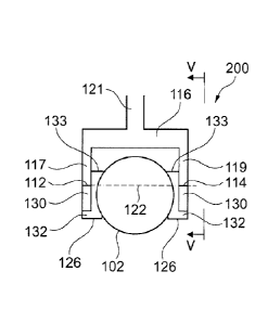
Fig. 3 shows a further stirring device 200 for a biogas fermenter according to
embodiments of the herein disclosed subject matter.
In accordance with embodiments of the herein disclosed subject matter the
mounting structure 106 shown in Fig. 3 comprises a first connection surface
112 and a second connection surface 114, which are located at opposite sides
of a shaft 102. However, the first element 108 and the second element 110
providing the first connection surface 112 and the second connection surface
114 are different from the ones shown in Fig. 1.
According to an embodiment shown in Fig. 3 each of the first element 108 and
the second element 110 comprises a first mounting part 124 and a second
mounting part 126. The first mounting part 124 and the second mounting part
CA 02921281 2016-02-12
WO 2015/022390 PCT/EP2014/067393
- 16 -
126 are attached to the shaft 102, e.g. by welding. It should be understood
that any other suitable attachment process may be suitable for attaching the
first and second mounting parts 124, 126 to the shaft 102. The first mounting
part 124 and that the second mounting part 126 are spaced in axial direction
128. Between the first mounting part 124 in the second mounting part 126 an
intermediate part 130 is provided which extends between the first mounting
part 124 and the second mounting part 126.
According to an embodiment, the first mounting part 124, the second
mounting part 126 and the intermediate part 130 are separate components.
According to an embodiment, the first mounting part 124 and the second
mounting part 126 have respective attachment surfaces 132 facing each
other. According to an embodiment, the intermediate part 130 is attached to
the attachment surfaces 132. According to other embodiments, the
intermediate part 130 may be attached to other portions of the first mounting
part 124 and the second mounting part 126.
In accordance with an embodiment the first connection surface 112 comprises
two surface portions 137, 139 spaced apart from each other in axial direction
128. Further, the second connection surface 114 comprises two surface
portions 138, 140 spaced apart from each other in the axial direction 128.
Fig. 4 shows a cross-sectional view of the stirring device 200 of Fig. 3 along
line IV-IV.
In accordance with an embodiment, each intermediate part 130 provides one
of the first connection surface 112 and the second connection surface 114, as
shown in Fig. 3. By using the first mounting part 124 (not shown in Fig. 4)
and
the second mounting part 126 for the connection to the shaft 102 and on the
other hand providing the intermediate part 130 for a connection to the
stirring
element 116, the connection plane 122 may be located closer to the axis of
rotation while the first mounting part 124 and the second mounting part 126
are connected to the shaft 102 over a relatively large angular range, as shown
for the second mounting part 126 in Fig. 4. Generally, this may be achieved by
the first connection surface 112 and the second connection surface 114 being
CA 02921281 2016-02-12
WO 2015/022390
PCT/EP2014/067393
- 17 -
spaced from a circumferential edge 133 of its associated mounting part 124,
126, wherein the connection surface 112, 114 faces the circumferential edge
133.
Fig. 5 shows a side view of the stirring device 200 of Fig. 4 when viewed from
line V-V.
In accordance with an embodiment, the first mounting part 124 extends over
a first angular range, indicated at 134 in Fig. 5 and the second mounting part
126 extends over the second angular range, indicated at 136 in Fig. 5.
According to an embodiment, the first angular range 134 and the second
angular range 136 overlap each other. For example, in an embodiment the
first angular range 134 and the second angular range 136 are identical, as
shown in Fig. 4. In other words, in this embodiment the first mounting part
124 in the second mounting part 126 are aligned with each other in axial
direction.
In accordance with an embodiment, the second leg 119 of the stirring element
116 is attached to the first surface portion 138 and the second surface
portion
140 of the second connection surface 114. In accordance with a further
embodiment, and as described above, the second leg 119 comprises an
opposing surface 120 which is attached to the second connection surface 114
of the second element 110 of the mounting structure 106. In accordance with
an embodiment, the opposing surface 120 has two surface portions 142, 144
which are spaced from each other in axial direction 128 and which are
configured to be attached to the respective surface portions 138, 140 of the
second connection surface 114. Likewise the opposing surface 118 of the first
leg 117 of the stirring element 116 has two surface portions which are spaced
from each other in axial direction (not shown in Fig. 5).
In accordance with an embodiment, the intermediate part 130 has a
circumferentially extended portion 146 between the two spaced apart surface
portions 138, 140 of the second connection surface 114 of the intermediate
part 130. In accordance with an embodiment, the circumferentially extended
CA 02921281 2016-02-12
WO 2015/022390 PCT/EP2014/067393
- 18 -
portion 146 comprises a recess 148 in the form of a through hole in order to
reduce the weight of the intermediate part 130.
Fig. 6 shows further stirring device 300 according to embodiments of the
herein disclosed subject matter.
According to an embodiment, the stirring device 300 comprises a mounting
structure 106 which comprises a first protrusion 150 extending in
circumferential direction 152 over the extent 154 of the intermediate part 130
.. at its connection surface 114. The first protrusion 150 connects the first
mounting part 124 and the intermediate part 130. In accordance with an
embodiment, the first protrusion 150 is an integral portion of the
intermediate
part 130, as shown in Fig. 6. According to other embodiments (not shown in
Fig. 6), the protrusion 150 may be provided by a separate part located
between the first mounting part 124 and the intermediate part 130. According
to an embodiment, the mounting structure 106 comprises two first protrusions
150 each extending in one of the two circumferential directions (clockwise and
counterclockwise), as shown in Fig. 6.
According to an embodiment, the mounting structure 106 and further
comprises a second protrusion 156 extending in circumferential direction 152
over the extent 154 of the intermediate part 130 at its connection surface
114. The second protrusion 156 connects the second mounting part 126 and
the intermediate part 130. The second protrusion 156 may be configured
similar or identical to the first protrusion 150. According to an embodiment,
a
second protrusion 156 is provided for each of the two circumferential
directions, as shown in Fig. 6.
Fig. 7 shows the mounting structure 106 of Fig. 6 in greater detail with the
stirring element 116 attached to the mounting structure 106.
According to an embodiment, the stirring element 116 is attached to the
second connection surface 114 with a bolt connection 160. The bolt connection
160 may include e.g. thread in the intermediate part 130. According to
another embodiment, the bolt connection 160 may include a threaded bolt 162
CA 02921281 2016-02-12
WO 2015/022390 PCT/EP2014/067393
- 19 -
with the retaining ring 164, wherein the threaded bolt extends through both,
the stirring element 116 and the intermediate part 130.
According to an embodiment, the mounting structure 106 comprises a
guidance 166, e.g. in the form of a drill bush as shown in Fig. 7, wherein the
guidance is configured for defining a position of the stirring element 116
with
respect to the second connection surface 114 if the stirring element is in
contact with the first connection surface (not shown in Fig. 7) and the second
connection surface 114. According to an embodiment a guidance is also
provided for the first connection surface (not shown in Fig. 7). Further,
while
in Fig. 7 a guidance 166 is shown for the second surface portion 140 of the
second connection surface 114, it should be understood that according to an
embodiment a guidance is also provided for the first surface portion 138 of
the
second connection surface 114 as well as for the surface portions 137, 139 of
the first connection surface 112 (see e.g. Fig. 3). According to an
embodiment, the guidance 166, e.g. the drill bush, also provides form-locked
join between the stirring element and the respective connection surface. In
particular, the guidance 166 shown in Fig. 7 provides for a form-locked join
between the stirring element 116 and the respective connection surface 114
and the transfers lateral forces between the stirring element 116 and the
connection surface 114, e.g. if the friction between respective connection
surface 114 and its opposing surface 120 is not sufficient for the force
transfer.
Having regard to the subject matter disclosed herein, it should be mentioned
that generally each of the first connection surface and the second connection
surface may be configured according to one or more of the embodiments
disclosed herein for one of these surfaces.
It should be noted that any entity disclosed herein (e.g. parts, portions,
surfaces, components, units, structures and devices) are not limited to a
dedicated entity as described in some embodiments. Rather, the herein
disclosed subject matter may be implemented in various ways and with
various granularity while still providing the specified functionality.
Further, it
CA 02921281 2016-02-12
WO 2015/022390 PCT/EP2014/067393
- 20 -
should be noted that according to embodiments a separate entity (e.g. part,
portion, surface, component, unit, structure or device) may be provided for
each of the functions disclosed herein. According to other embodiments, an
entity (e.g. part, portion, surface, component, unit, structure or device) is
configured for providing two or more functions as disclosed herein. According
to still other embodiments, two or more entities (e.g. part, portion, surface,
component, unit, structure or device) are configured for providing together a
function as disclosed herein.
Generally herein, and attachment of two pieces to each other may be
performed by any suitable means, including one or more of welding, gluing,
bolting, riveting, etc.
It should be noted that the term "comprising" does not exclude other elements
or steps and the "a" or "an" does not exclude a plurality. Also elements
described in association with different embodiments may be combined. It
should also be noted that reference signs in the claims should not be
construed as limiting the scope of the claims.
In order to recapitulate the above described embodiments of the present
invention one can state:
In accordance with embodiments of the herein disclosed subject matter it is
described a stirring device 200 for a biogas fermenter wherein the stirring
device 200 is configured for stirring a fermentation material and comprises a
shaft 102 rotatable about an axis of rotation and a mounting structure 106
attached to the shaft 102. The mounting structure 106 has a first connection
surface 112 and the second connection surface 114 and a stirring element 116
is attached to the first connection surface 112 and the second connection
surface 114. The first connection surface 112 and the second connection
surface 112 are located at opposite sides of the shaft 102 with the shaft
being
located between the first connection surface 112 and the second connection
surface 114. The stirring element 116 may be configured to be spaced from
the shaft 102 when the stirring element 116 is attached to the first
connection
CA 02921281 2016-02-12
WO 2015/022390
PCT/EP2014/067393
- 21 -
surface 112 and the second connection surface 114. According to an
embodiment, the stirring device 200 is adapted for stirring fermentation
material which is subject to dry fermentation.
CA 02921281 2016-02-12
WO 2015/022390
PCT/EP2014/067393
- 22 -
List of reference signs:
100, 200, 300 stirring device
102 shaft
104 axis of rotation
106 mounting structure
108 first element
110 second element
112 first connection surface
114 second connection surface
116 stirring element
117 first leg
118 opposing surface
119 second leg
120 opposing surface
121 body
122 connection plane
124 first mounting part
126 second mounting part
128 axial direction
130 intermediate part
132 attachment surface
133 circumferential edge of 124 or 126
134 first angular range
136 second angular range
137 surface portion of 112
138 surface portion of 114
139 surface portion of 112
140 surface portion of 114
142, 144 surface portions of 120
146 circumferentially extended portion of 130
148 recess
CA 02921281 2016-02-12
WO 2015/022390
PCT/EP2014/067393
- 23 -
150 first protrusion
152 circumferential direction
154 extent of 130 at 114
156 second protrusion
160 bolt connection
162 threaded bolt
164 retaining the ring
166 guidance