Note: Descriptions are shown in the official language in which they were submitted.
CA 02921320 2016-02-12
1
DESCRIPTION
TITLE OF THE INVENTION
FRICTION STIR WELDING METHOD
TECHNICAL FIELD
[0001] The
present invention relates to a friction stir welding method, and more
particularly to a method of advantageously joining together members formed of
materials
which are considered difficult to be joined together by the friction stir
welding method,
such as a cast aluminum alloy and 2000 series, 4000 series, 5000 series and
7000
series aluminum alloys, by the friction stir welding method using a rotary
tool such as a
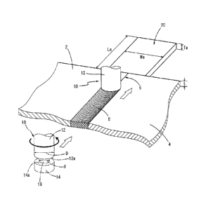
bobbin tool and a self-reacting tool, which has two shoulder members and which
is
configured to perform a friction stir welding operation so that the members to
be joined
together are interposed between the two shoulder members, and a pressure is
applied to
those members through the two shoulder members.
BACKGROUND ART
[0002] A
friction stir welding (FSW) method has been recently proposed in
JP-T-7-505090, for example. The friction stir welding method is performed by
inserting
a rotary tool (specifically, a probe or a pin) into portions of two members to
be joined
together while rotating the rotary tool, to stir materials of those members
and force the
materials to flow by utilizing a friction heat, whereby those members are
joined together
in solid states without their fusion. A thermal strain is not likely to be
generated by the
friction stir welding method, since an amount of heat generated in an area
welded by the
friction stir welding method is smaller than an amount of heat generated in an
area
welded by a conventional fusion welding method. Further, the friction stir
welding
method permits joining of the members in the solid states, without phase
transition which
is characteristic of the fusion welding method in which the members to be
joined together
are molten and then solidified. For the above-described reasons, the friction
stir
welding method permits formation of a sound welded area. Accordingly, the
friction stir
welding method has been attracting attention, and employed in wider fields,
particularly
for joining together members formed of aluminum materials. The friction stir
welding
method greatly contributes to an increase of applications of the aluminum
materials
which are frontrunner materials that permit weight reduction. For
instance, the
aluminum materials can be used for structural members of transportation
vehicles such
as an automobile and a railway car, and housings of IT equipment, by
performing the
friction stir welding method for production of the structural members and
housings.
[0003] By
the way, the rotary tool used in the friction stir welding method
described above generally has a structure in which a protrusion which is
called the probe
and which has a predetermined length is provided in a central part of a distal
end portion
of a cylindrical shoulder member. The friction stir welding method is
performed by
CA 02921320 2016-02-12
2
inserting a distal end of the probe into portions of the members to be joined
together
while rotating the shoulder member of the rotary tool about its axis, and
joining together
those members along a line or at a spot while applying a pressure to the
above-described portions through a shoulder surface of the shoulder member, as
disclosed in JP-T-7-505090 described above. However, in the friction stir
welding
method using the rotary tool constructed as described above, it is necessary
to dispose a
backing plate such as a surface plate on the back side of the portions which
are to be
joined together and into which the probe is to be inserted, so that a pressing
force
applied by the rotary tool to the above-described portions during the joining
operation is
received by the backing plate. Otherwise, the members to be joined together
would be
deformed by the pressure applied by the rotary tool, giving rise to a problem
of failure of
joining of those members. Therefore, it has been difficult to employ the
friction stir
welding method for joining of hollow members, since it is difficult to dispose
the backing
plate with respect to the hollow members.
[0004] Under
the above-described circumstances, there has been proposed a
rotary tool which does not require the use of the backing plate. The rotary
tool has a
cylindrical first shoulder member, and a second shoulder member which is
provided at
the distal end of the probe projecting from the first shoulder member, and
which is
opposed to the first shoulder member. The rotary tool is configured to perform
a friction
stir welding operation by simultaneously applying a pressure to both of the
front and
back surfaces of the portions of the members to be joined together, through
the
respective two shoulder members described above. For instance, there has been
disclosed a friction stir welding method using a so-called bobbin tool having
a structure in
which the two shoulder members are fixedly connected with each other through
the
probe, in JP-A-2003-154471, for example.
Further, JP-A-2003-181654 and
JP-A-2009-18312, for example, propose so-called self-reacting tools in which
one of the
two shoulder members is configured so as to be movable with respect to the
probe in its
axial direction, so that a distance between the two shoulder members can be
changed.
By using the rotary tools described above, the hollow members and the like can
be
joined together without using the backing plate, whereby applications of the
friction stir
welding method have been further increased.
[0005] By
the way, among aluminum members to be joined together, members
formed of a cast aluminum alloy and 2000 series, 4000 series, 5000 series and
7000
series aluminum alloys according to JIS are considered difficult to be joined
together by
the friction stir welding method, since metals of those members are difficult
to be
friction-stirred, and are not sufficiently forced to flow by a friction-
stirring action. In the
case where the above-indicated aluminum members are joined together by the
friction
stir welding method by using the rotary tool having the two shoulder members,
such as
the bobbin tool and self-reacting tool described above, the metals of those
aluminum
CA 02921320 2016-02-12
3
members tend to stick to the circumferential surface of the probe of the
rotary tool.
Accordingly, when the friction stir welding operation is terminated and the
rotary tool is
removed from a welded area, the metals adhere or firmly stick to the
circumferential
surface of the probe of the rotary tool, giving rise to a problem that an
extra work is
required to remove the metals, and the rotary tool cannot be used for a
subsequent
friction stir welding operation, right after the last friction stir welding
operation. Further,
the metals of the aluminum members adhering to the rotary tool are removed
from
portions of the aluminum members where the rotary tool is removed from the
welded
area, resulting in formation of a large unwelded area in the above-described
portions.
Accordingly, it is necessary to cut off end portions of the members joined
together on the
side of termination of the welding operation, by a large amount, resulting in
a loss of the
materials.
PRIOR ART DOCUMENTS
PATENT DOCUMENTS
[0006] Patent Document 1: JP-T-7-505090
Patent Document 2: JP-A-2003-154471
Patent Document 3: JP-A-2003-181654
Patent Document 4: JP-A-2009-18312
SUMMARY OF THE INVENTION
TECHNICAL PROBLEM
[0007] The present invention was made in view of the background arts
described above. It is an object of the invention to provide a method of
joining together
two members formed of the same material or respective different materials
selected from
a cast aluminum alloy and 2000 series, 4000 series, 5000 series and 7000
series
aluminum alloys which are considered difficult to be joined together by the
friction stir
welding method, by performing a friction stir welding operation using a rotary
tool having
two shoulder members, so that metals of the members to be joined together are
advantageously prevented from sticking to the rotary tool at the time of
termination of the
friction stir welding operation, to effectively improve efficiency of use of
the rotary tool.
SOLUTION TO PROBLEM
[0008] The above-described object of the invention can be achieved
according
to the principle of the invention, which provides a friction stir welding
method comprising:
joining together joining portions of a first member and a second member by a
friction stir
welding operation performed by moving a probe of a rotary tool in a direction
of
extension of the joining portions, while rotating the probe in the form of a
rod by rotation
of the rotary tool together with two shoulder members which are provided on
the probe
so as to be spaced apart from each other by a predetermined distance in an
axial
direction of the probe, and applying a pressure to the joining portions
through the two
shoulder members, wherein the first and second members are formed of the same
CA 02921320 2016-02-12
4
material or respective different materials selected from a group consisting of
a cast
aluminum alloy and 2000 series, 4000 series, 5000 series and 7000 series
aluminum
alloys; disposing a termination tab member formed of a 1000 series, 3000
series, 6000
series or 8000 series aluminum alloy in abutting contact with end faces of the
joining
portions of the first and second members on the side of termination of the
friction stir
welding operation; and terminating the friction stir welding operation by
moving the probe
of the above-described rotary tool from the joining portions of the first and
second
members into the termination tab member.
[0009] In a preferred form of the friction stir welding method according
to the
invention, the termination tab member is a planar member having a length not
shorter
than four times a diameter of the shoulder members, in a direction of welding
of the first
and second members by the rotary tool, and a width not shorter than twice the
diameter
of the shoulder members, in a direction perpendicular to the direction of
welding of the
first and second members.
[0010] In a preferred form of the friction stir welding method according
to the
invention, the termination tab member has a thickness not larger than a half
of a
diameter of the probe of the rotary tool.
[0011] The friction stir welding method according to the invention is
practiced,
for example, by butting the joining portions of the first and second members
on each
other to provide an abutting part, and performing the friction stir welding
operation with
respect to the abutting part. Alternatively, the friction stir welding method
according to
the invention is practiced by superposing the joining portions of the first
and second
members on each other, and performing the friction stir welding operation with
respect to
an overlapping part in which the joining portions are superposed on each
other.
[0012] The rotary tool preferably used in the present invention is
generally a
bobbin tool in which the two shoulder members are fixedly provided on the
probe, with
the predetermined distance therebetween. Alternatively, the rotary tool
preferably used
in the present invention is a self-reacting tool in which one of the two
shoulder members
is fixed to the probe, and the other of the two shoulder members is configured
so as to be
movable in the axial direction of the probe, so that the distance between the
two
shoulder members can be changed.
ADVANTAGEOUS EFFECTS OF THE INVENTION
[0013] In the present invention, when the joining portions of the
members
formed of the specific aluminum materials which are not easily joined together
by the
friction stir welding method are joined together by the friction stir welding
method by
using the rotary tool having the two shoulder members, the termination tab
member
formed of one of 1000 series, 3000 series, 6000 series and 8000 series
aluminum alloys
according to JIS, whose metals can be easily friction-stirred, is disposed in
abutting
contact with the end faces of the above-described joining portions of the
members on the
CA 02921320 2016-02-12
side of termination of the welding operation, and after the friction stir
welding operation
with respect to the above-described joining portions is performed, the rotary
tool is
inserted from the above-described joining portions into the termination tab
member,
while the rotary tool is rotated, and moved through the terminating tab
member, while the
termination tab member is friction-stirred by the rotary tool. Accordingly,
metals firmly
stuck to the circumferential surface of the probe of the rotary tool during
the friction stir
welding operation with respect to the above-described joining portions can be
effectively
removed by friction-stirring of the metal of the termination tab member.
Therefore,
when the rotary tool is removed out of the termination tab member, almost no
metal
adheres to the rotary tool, so that there is no need to perform an operation
for removing
the metal from the rotary tool, and the rotary tool can be used for a
subsequent friction
stir welding operation, without being subjected to any operation.
[0014] Moreover, in the presence of the termination tab member according
to
the present invention, it is possible to smoothly shift the friction-stirring
operation by the
rotary tool from a friction-stirring operation with respect to the metals of
the joining
portions of the first and second members, to a friction-stirring operation
with respect to
the metal of the termination tab member, since the metal of the termination
tab member
can be easily friction-stirred, whereby the metals can be effectively supplied
to the end
parts of the joining portions of the first and second members on the side of
termination of
the welding operation, resulting in effective prevention of generation of a
void and an
unwelded area in the above-indicated end parts. Accordingly, there is no need
to cut off
the end parts of the joining portions on the side of termination of the
welding operation,
by a large amount, whereby a loss of the materials can be advantageously
reduced.
BRIEF DESCRIPTION OF THE DRAWINGS
[0015] Fig. 1 is a schematic perspective view showing an example of a
state of
a friction stir welding method according to the invention, on the side of
termination of a
welding operation;
Fig. 2 is a schematic plan view showing a movement of a rotary tool
used for the friction stir welding method on the side of termination of the
welding
operation shown in Fig. 1;
Figs. 3 are schematic axial cross sectional views showing examples of
the rotary tool used in the invention, in which Fig. 3(a) is a schematic axial
cross
sectional view of an example of a bobbin tool, and Fig. 3(b) is a schematic
axial cross
sectional view of an example of a self-reacting tool; and
Fig. 4 is a schematic perspective view showing another example of the
friction stir welding method according to the invention.
MODE FOR CARRYING OUT THE INVENTION
[0016] To clarify the invention more specifically, a friction stir
welding method
according to the invention will be described by reference to the drawings.
CA 02921320 2016-02-12
6
[0017] Referring first to Fig. 1, there is shown a state of the friction
stir welding
method according to the invention on the side of termination of a welding
operation. In
the embodiment shown in Fig. 1, a first member 2 and a second member 4 are
butted on
each other in their planar portions to form an abutting part 6, and the
friction stir welding
operation is performed with respect to the abutting part 6, whereby the first
and second
members 2 and 4 are joined together along a line, to obtain a product in the
form of a
one-piece body of those members 2 and 4.
[0018] Each of the first and second members 2 and 4 to be joined
together is
formed of any one of a cast aluminum alloy, a 2000 series (Al-Cu-based)
aluminum alloy,
a 4000 series (Al-Si-based) aluminum alloy, a 5000 series (Al-Mg-based)
aluminum alloy
and a 7000 series (Al-Zn-Mg-based) aluminum alloy according to JIS, which
materials
are difficult to be joined together. The first and second members 2 and 4 may
be
formed of the same material or respective different materials. As the member
formed of
the cast aluminum alloy, there is used a cast member which has a planar
portion and
which is obtained by a conventional casting process by using an aluminum alloy
represented by "AC" and a digit and one or two alphabetic character or
characters
following "AC", according to JIS, and a cast member which has a planar portion
and
which is obtained by a die casting process by using an aluminum alloy
represented by
"ADC" and one or two digit or digits following "ADC", according to JIS, for
example. On
the other hand, the members formed of the 2000 series, 4000 series, 5000
series and
7000 series aluminum alloys indicated above are used in the form of various
wrought
products having a planar portion, such as a rolled sheet member and an
extruded
member.
[0019] A rotary tool 10 as shown in Fig. 1 is used in the friction stir
welding
method, to join together joining portions of the above-described first and
second
members 2 and 4 which cooperate to provide the abutting part 6. Namely, the
rotary
tool 10 used in this embodiment is a bobbin type tool having a structure
similar to that of
the conventional bobbin type tool, and has an upper shoulder member 12 and a
lower
shoulder member 14, which have the same diameter (D), and which are connected
with
each other through a probe 16 in the form of a rod, such that the upper and
lower
shoulder members 12 and 14 are coaxially opposed to each other with a
predetermined
distance therebetween, and integrally rotatable about their axes. Thus, the
rotary tool
is configured such that in the friction stir welding operation, the probe 16
is inserted
into the abutting part 6 of the first and second members 2 and 4, while the
probe 16 is
rotated and while a pressure is applied to the abutting part 6 interposed
between an
upper shoulder surface 12a of the upper shoulder member 12 and a lower
shoulder
surface 14a of the lower shoulder member 14, in the downward and upward
directions
through the respective upper and lower shoulder surfaces 12a and 14a, whereby
metals
of the two members 2 and 4 are friction-stirred and forced to flow in the
abutting part 6,
CA 02921320 2016-02-12
7
and the two members 2 and 4 are joined together.
[0020] By the way, in the case where the friction stir welding operation
is
performed by inserting the probe 16 of the bobbin type rotary tool 10
described above
into the abutting part 6 of the first and second members 2 and 4 whose metals
are not
easily friction-stirred and forced to flow, and by moving the probe 16 in the
direction
(welding direction) of extension of the abutting part 6 to join together the
first and second
members 2 and 4 along a line, the metals of the first and second members 2 and
4 tend
to stick to the circumferential surface of the probe 16 of the rotary tool 10.
Accordingly,
when the friction stir welding operation is terminated and the rotary tool 10
is removed
from the abutting part 6, the metals firmly stick to the circumferential
surface of the probe
16 of the rotary tool 10, giving rise to a problem that an extra work is
required to remove
the metals. Further, the metals are not supplied to an end portion of the
abutting part 6
on the side of termination of the welding operation, resulting in generation
of an
unwelded area in the above-described end portion. Accordingly, it is necessary
to cut
off the above-described unwelded area from the obtained product, giving rise
to a
problem of a significant loss of the materials, for example.
[0021] Therefore, in the present invention, in order to solve the above-
described
problems at the time of termination of the friction stir welding operation, a
termination tab
member 20 formed of a specific aluminum alloy material which is easily forced
to flow by
the friction-stirring action is disposed in abutting contact with end faces of
the joining
portions of the first and second members 2 and 4 (in the abutting part 6), on
the side of
termination of the welding operation, as shown in Fig. 1, and the probe 16 of
the bobbin
type rotary tool 10 is moved from the abutting part 6 into the termination tab
member 20,
to terminate the friction stir welding operation.
[0022] As the termination tab member 20 disposed in abutting contact
with the
end faces of the joining portions of the members 2 and 4 on the side of
termination of the
welding operation, there is used a member which is formed of a 1000 series
aluminum
alloy (pure aluminum), a 3000 series (Al-Mn-based) aluminum alloy, a 6000
series
(Al-Mg-Si-based) aluminum alloy or an 8000 series aluminum alloy according to
JIS, and
which has a suitable shape and suitable dimensions. Generally, a planar
rectangular
member as shown in Fig. 1 is preferably used as the termination tab member 20.
All of
the above-indicated specific aluminum alloys giving the termination tab member
20
exhibit sufficiently high fluidity when they are friction-stirred. Therefore,
by inserting the
probe 16 of the rotary tool 10 from the abutting part 6 of the first and
second members 2
and 4 into the termination tab member 20 formed of the material described
above, and
moving the probe 16 through the termination tab member 20, the metals firmly
sticking to
the circumferential surface of the probe 16 of the rotary tool 10 are
effectively removed
while the probe 16 is moved through the termination tab member 20.
[0023] Namely, after the abutting part 6 of the first and second members
2 and 4
CA 02921320 2016-02-12
8
has been friction-stir-welded by moving the rotary tool 10 relative to the
first and second
members 2 and 4 along the abutting part 6, while the rotary tool 10 is rotated
about its
axis and while the pressure is applied to the abutting part 6 by the upper and
lower
shoulder members 12 and 14, the rotary tool 10 is inserted into the
termination tab
member 20 from the welding-terminal edge of the abutting part 6, and
successively
moved through the termination tab member 20, while the rotary tool 10 is
rotated so as to
friction-stir the metal of the termination tab member 20, whereby the metals
firmly stuck
to the circumferential surface of the probe 16 or the other parts of the
rotary tool 10
during the friction stir welding operation performed with respect to the
abutting part 6 of
the first and second members 2 and 4 are effectively removed by the friction-
stirring of
the metal of the termination tab member 20 while the rotary tool 10 is moved
through the
termination tab member 20. As a result, when the rotary tool 10 is removed out
of the
termination tab member 20, almost no metal adheres to the rotary tool 10.
Accordingly,
there is no need to perform a cumbersome operation for removing the metals
from the
rotary tool 10, and the rotary tool 10 can be repeatedly used for a subsequent
friction stir
welding operation, without being subjected to any operation after its use,
whereby
efficiency of use of the rotary tool 10 can be advantageously increased.
[0024] Moreover, when the probe 16 of the rotary tool 10 is inserted
into the
termination tab member 20 from the abutting part 6 of the first and second
members 2
and 4, the metal of the termination tab member 20 can be effectively forced to
flow
toward the welding-terminal edge of the abutting part 6 by the friction-
stirring action by
the rotary tool 10, since the termination tab member 20 is formed of the
specific
aluminum alloy material having sufficiently high fluidity, resulting in
effective prevention
of generation of an unwelded area in the end portion of the abutting part 6 on
the side of
termination of the welding operation. Accordingly, sound welding can be
performed on
the side of termination of the welding operation, resulting in effective
reduction of an
amount of stock required to be cut off from the above-described end portion,
leading to
advantageous reduction of a loss of the materials.
[0025] By the way, the first and second members 2 and 4 to be subjected
to the
friction stir welding operation are generally butted on each other in their
planar portions
having a substantially equal thickness (t), to form the abutting part 6, and
the thickness
(Te) of the termination tab member 20 disposed in abutting contact with the
end faces of
those members 2 and 4 in the abutting part 6 on the side of termination of the
welding
operation is set so as to be substantially equal to the thickness (t) of the
first and second
members 2 and 4 in the abutting part 6. Although the dimensions of the
termination tab
member 20 are adequately selected such that the object of the invention can be
achieved, the length (Le) of the termination tab member 20 in the direction of
extension
of the abutting part 6, i.e. in the direction of welding of the first and
second members 2
and 4 shown in Fig. 1 is preferably set so as to be not shorter than four
times the
CA 02921320 2016-02-12
9
diameter (D) of the shoulder members 12 and 14 of the rotary tool 10, in other
words, not
shorter than four times the diameter of the shoulder surfaces 12a and 14a of
the
respective shoulder members 12 and 14. Further, the width (We) of the
termination tab
member 20 in the direction perpendicular to the direction of its length (Le)
in the welding
direction is preferably set so as to be not shorter than twice the diameter
(D) of the
shoulder members 12 and 14 of the rotary tool 10. The size and shape of the
termination tab member 20 are adequately determined so as to meet the
above-described requirements regarding its length (Le) and width (We).
Further, the
thickness (Te) of the termination tab member 20 is preferably set so as to be
not larger
than a half of the diameter (d) of the probe 16 of the rotary tool 10, whereby
the friction
stir welding operation according to the invention can be more advantageously
performed.
[0026] In this embodiment, the shoulder members 12 and 14 of the rotary
tool
have the same diameter. However, it is also possible to set the diameters of
the
shoulder members 12 and 14 at respective different values. In this case, it is
desirable
to set the diameter of the upper shoulder member 12 so as to be larger than
that of the
lower shoulder member 14. Where the diameters of the shoulder members 12 and
14
are different from each other, the diameter of one of the two shoulder members
12 and
14 whose shoulder surface has a larger diameter than the shoulder surface of
the other
of the two shoulder members 12 and 14 is defined as the diameter (D) described
above.
The above-described diameter (D) of the shoulder members 12 and 14 is
generally set
so as to be larger than the diameter (d) of the probe 16 by at least 4mm.
Further, in the
case where the diameters of the shoulder members 12 and 14 are set at
respective
different values as described above, the diameter of one (shoulder member 14)
of the
two shoulder members 12 and 14 which is smaller than that of the other of the
two
shoulder members is set so as to be not smaller than a sum of the diameter (d)
of the
probe 16 and 2mm.
[0027] By the way, as the rotary tool 10 used for the friction stir
welding
operation described above, it is possible to adequately use various kinds of
known rotary
tool configured to perform the friction stir welding operation by its rotary
motion while
applying a pressure to the abutting part 6 (joining portions) of the first and
second
members 2 and 4 through the two shoulder members 12 and 14 which are provided
on
the probe in the form of a rod so as to be spaced apart from each other by a
predetermined distance. For instance, it is possible to use a so-called bobbin
tool 10
having a structure in which the upper shoulder member 12 and the lower
shoulder
member 14 are coaxially and fixedly connected with each other through the
probe 16,
such that the upper and lower shoulder members 12 and 14 are opposed to each
other
and spaced apart from each other by the predetermined distance, as shown in
Fig. 3(a).
In the bobbin tool 10, the lower shoulder member 14 is screwed on the probe
16,
CA 02921320 2016-02-12
whereby the length of the probe 16 between the two shoulder members 12 and 14
is
defined. Further, the lower shoulder member 14 is fixed in position by a
locking nut 18
screwed on the probe 16 to prevent displacement of the lower shoulder member
14.
Alternatively, it is also possible to use a so-called self-reacting tool 11
having a structure
in which a probe 17 is coaxially fixed to a lower shoulder member 15 of two
shoulder
members, and inserted through the upper shoulder member 13 so as to extend in
its
axial direction, as shown in Fig. 3(b), such that the probe 17 is movable in
its axial
direction with respect to the upper shoulder member 13, so that the distance
between
the upper and lower shoulder members 13 and 15 can be changed.
[0028] The distance (length of the probe 16, 17) between the two
shoulder
members 12 and 14, and 13 and 15 is set so as to be smaller by a suitable
amount than
the thickness of the abutting part 6 (termination tab member 20), so that an
adequate
pressing action can be applied to the abutting part 6 in which the two members
2 and 4
are joined together. Further, the self-reacting tool 11 may be configured such
that its
upper and lower shoulder members 13 and 15 are rotated in the same direction,
or in
respective different directions. The friction stir welding operation performed
by using
the rotary tool 10 according to the invention, such as the above-described
bobbin tool 10
and self-reacting tool 11, is advantageously employed in the case where the
thickness of
the joining portions, for example, the thickness (t) of the first and second
members 2 and
4 is not smaller than 2mm. In the present invention, the upper limit of the
thickness (t)
of the first and second members 2 and 4 is generally set at about lOmm.
[0029] In the above-described embodiment, the friction stir welding
operation is
performed with respect to the abutting part 6 of the first and second members
2 and 4, to
join together those members 2 and 4 along a line. However, the present
invention is
also applicable to a method of performing the friction stir welding operation
with respect
to an overlapping part 36 in which a planar flange portion 32a of an upper
member 32
(first member) having a hat-like cross sectional shape and a planar flange
portion 34a of
a lower member 34 (second member) having a hat-like cross sectional shape are
superposed on each other, so that the upper and lower members 32 and 34
cooperate to
form a hollow body 30, as shown in Fig. 4. In this embodiment, a termination
tab
member 24 having a thickness similar to that of the overlapping part 36 of the
planar
flange portions 32a and 34a is held in abutting contact with a longitudinal
end face of the
overlapping part 36, and the friction stir welding operation is terminated
after the rotary
tool 10 has been moved from the overlapping part 36 into the termination tab
member 24.
Accordingly, the rotary tool 10 is inserted from the overlapping part 36 into
the
termination tab member 24, while being rotated about its axis, to terminate
the friction stir
welding operation. At this time, the metals firmly sticking to the probe 16 of
the rotary
tool 10 can be effectively removed by moving the rotary tool 10 through the
termination
tab member 24 by a predetermined distance according to the invention, whereby
CA 02921320 2016-02-12
11
substantially the same effects as achieved in the above-described embodiment
can be
achieved.
[0030] In the embodiment shown in Fig. 4, the termination tab member 24
is
disposed in abutting contact with the longitudinal end face of the overlapping
part 36 of
the flange portions 32a and 34a. However, it is also possible to dispose the
termination
tab member (24) in abutting contact with a widthwise end face of the
overlapping part 36,
and perform the friction stir welding operation by changing the direction of
movement of
the rotary tool 10 by 90 to move the rotary tool 10 from an end portion of
the overlapping
part 36 on the side of termination of the welding operation into the
termination tab
member (24). In this case too, substantially the same effects as achieved in
the
above-described embodiments can be achieved.
[0031] By terminating the friction stir welding operation as described
above, it is
possible to obtain a product having a sound end portion in a friction-stir-
welded area 8,
38, on the side of termination of the welding operation, while preventing the
metals from
sticking to the probe 16 of the rotary tool 10. In this respect, it is noted
that the
termination tab member 20 adheres to the thus obtained product through the
friction-stirred metals, on the side of termination of the welding operation.
However, the
termination tab member 20 can be easily mechanically broken off from the
product, so
that the product having the sound welded area 8, 38 can be easily obtained. In
the
present invention, it is also advantageous to cut and remove the metals
adhering to the
end faces of the first and second members 2 and 4 by using a machining device
such as
a grinder to finish those end faces, as necessary, after removing the
termination tab
member 20 as described above.
[0032] The product obtained by the friction stir welding method
described above
has the improved welded area, so that the present invention can be
advantageously
applied to a technique of producing a large member by joining together wrought
products
in the form of sheet members, extruded members, or the like, and cast members.
Further, the thus obtained product can be advantageously used as a structural
member
of a railway car and a structural member of an automobile, such as a subframe,
for
example, which exhibit required properties.
EXAMPLES
[0033] To clarify the invention more specifically, examples of the
invention will
be described. However, it goes without saying that the invention is by no
means limited
to the details of the illustrated examples. Further, it is to be understood
that the
invention may be embodied with various changes, modifications and
improvements,
which are not illustrated herein and which may occur to those skilled in the
art, without
departing from the spirit of the invention.
[0034] ¨ Example 1 ¨
A planar first member (2) and a planar second member (4) each of which
CA 02921320 2016-02-12
12
is formed of one of various aluminum materials indicated in Tables 1 and 2
given below,
and has a thickness (t) of 2.8-9.2mm, a width of 300mm and a length of 5000mm
were
butted on each other at their side faces which are opposed to each other in
the direction
of their width, to provide an abutting part (6). The first and second members
(2, 4) were
fixed on a table having a gap provided so as to be located below the abutting
part (6) of
the two members (2, 4). A planar termination tab member (20) which is formed
of one
of various aluminum materials indicated in Tables 1 and 2 and has a thickness
(Te), a
length (Le) in a welding direction and a width (We) in a direction
perpendicular to the
welding direction, as indicated in Tables 1 and 2, was held in abutting
contact with an
end portion of the abutting part (6) of the two members (2, 4) on the side of
termination of
the welding operation, as shown in Fig. 1, and fixed on the table, like the
above-described two members (2, 4).
[0035] On the other hand, a bobbin tool having two shoulder members (12,
14)
and a probe (16) as shown in Fig. 3(a) was used as the rotary tool (10). The
diameter
(D) of the two shoulder members (12, 14), the length of the probe (16) between
two
shoulder surfaces (12a, 14a) and the diameter (d) of the probe (16) are
indicated in
Tables 1 and 2. A friction stir welding operation was performed with respect
to the
abutting part (6) of the first and second members (2, 4) under conditions of a
rotational
speed and a welding speed indicated in Tables 1 and 2, by moving the bobbin
tool (10)
along the abutting part (6), while applying a pressure to the abutting part
(6) in the
upward and downward directions. Then, the bobbin tool (10) was inserted from
the
welding-terminal edge of the abutting part (6) into the termination tab member
(20), and
further moved through the termination tab member (20) in its longitudinal
direction, as
shown in Fig. 2, whereby the friction stir welding operation was terminated.
[0036] When the friction stir welding operation was terminated as
described
above, the bobbin tool (10) was observed to examine a degree of adhesion of
metals to
the bobbin tool (10). Further, the friction stir welding operation was
performed again as
described above, by using the bobbin tool (10) that had been used once for the
friction
stir welding operation, without subjecting the bobbin tool (10) to any other
treatment after
its use. Percentages of success of the second friction stir welding operation
are shown
in Tables 1 and 2. The friction stir welding operation was evaluated in terms
of the
degree of adhesion of the metals to the bobbin tool (10), as "Good" where
almost no
metal adhered to the bobbin tool (10), "Average" where adhesion of the metals
to the
bobbin tool (10) was recognized, and "Poor" where considerable adhesion of the
metals
to the bobbin tool (10) was recognized.
CA 02921320 2016-02-12
13
[0037] Table 1
FSW Example
1 2 3 4 5
CZ
JIS material 7075 7050 5182 5052 4343
I Temper T76 T7451 0 0 0
a)
E _____________________________________________________________________
E' Thickness: t(mm) 3.2 6.6 6.2 4.9 8.0
JIS material 7075 5052 5182 6063 6061
1
, ______________________________________________________________________
Temper T76 0 0 T6 T6
7:3 -
c
0
(..)
a) Thickness:t(mm) 3.2 6.6 6.2 4.9 8.0
u)
JIS material 8011 1200 3003 3105 6082
.0
g c'L-I Thickness: Te(mm) 3.2 6.6 6.2 4.9
8.0
iT1 15 ___________________________________________________________
c
--- E Length: Le(mm) 80 63.9 71.0 50.5 75.3
E a)
145 E ____________________________________________________________
I-
Width :We(mm) 40 32.6 40.4 22.7 39.7
Diameter: D
(mm) of shoulder 15 18.9 22.9 16.3 24.6
a
members
75 ____________________________________________________________________
o Length
(3' (mm) of probe 3 6.1 6.1 4.7 7.6
ct Diameter : d
8 14.2 17.0 11.2 16.9
(mm) of probe
Rotational speed
u) 1000 1500 1200 1100 900
cy) c
c .Eco (rpm)
Welding speed
500 1000 600 800 500
(mm/min.)
Adhesion of metals Good Good Good Good Good
Percentage (%) of success of
100 100 100 100 100
the second FSW
CA 02921320 2016-02-12
14
(Table 1 continued)
FSW Example
6 7 8 9 10
JIS material 4004 2024 2219 ADC3 ADC12
16 ________________________________________________________________ .
f
a) Temper 0 T3 T6 T6 0
E _________________________________________________________________
E, Thickness : t(mm) 3.2 2.8 3.7 6.8
3.6
4-)
-? JIS material 2014 2024 7003 ADC3 6N01
a)
E -4- Temper T4 T3 T5 T6 T4
-0 -
c
o
c.)
a) Thickness : t(mm) 3.2 2.8 3.7 6.8
3.6
(n
JIS material 6101 6061 6063 3004 6N01
_a
co a ______________________________________________________________
co ----" Thickness : Te(mm) 3.2 2.8 3.7
6.8 3.6
a) _o _____________________________________________________________
c
Length : Le(mm) 32.9 35.3 44.6 76.4 45.1
16 E ______________________________________________________________
I-
Width :We(mm) 14.6 21.7 18.7 34.7 26.8
Diameter: D
6- (mm) of shoulder 11.3 12.9 17.3 21.4
19.4
members
-6 ________________________________________________________________
o Length
3.2 2.6 3.5 6.4 3.6
a3 (mm) of probe
'f(2.
Diameter: d
6.7 8.6 9.3 17.0 10.4
(mm) of probe
Rotational speed
ci)
0) c 900 800 800 1000 900
c
' 'Po (rpm)
6
Welding speed
(.) 500 300 400 500 500
(mm/min.) _ __________________________________
Adhesion of metals Good Good Good Good Good
Percentage ( /0) of success of
100 100 100 100 100
the second FSW
CA 02921320 2016-02-12
[0038] Table 2
FSW Example
11 12 13 14 15
JIS material AC4C 7075 7075 7050 5182
4-) ___________________________________________________________________
1) Temper T6 T76 T76 T7451 0
E _____________________________________________________________________
rn
Thickness:t(mm) 8.9 3.2 3.2 9.2 7.8
1 JIS material 7N01 7075 7075 5052 5182
a.)
Temper T6 T76 T76 H34 0
-0 ---
c
o
0
a) Thickness:t(mm) 8.9 3.2 3.2 9.2 7.8
co
_ ______________________________________________________________________
JIS material 1100 - 7075 5182 5182
2 a _____________________________________________________________
g
-- Thickness: Te(mm) 8.9 - 3.2 9.2 7.8
2 -0
.E E Length: Le(mm) 87.2 - 80 96.5 82.1
1¨
Width :We(mm) 47.4 - 40 52.0 42.8
Diameter: D
a (mm) of shoulder 25.6 15 15 30.9 24.5
members
"5 ____________________________________________________________________
0 Length
cs' (mm) of probe 8.4 3 3 9.0 7.6
15)
w Diameter: d
20.6 8 8 23.2 19.0
(mm) of probe __________________________________________________________ .
Rotational speed
0,
0) c 800 1000 1000 1500 1200
c
f .io (rpm)
i. g, ___________________________________________________________
cS Welding speed
400 500 500 1000 600
0
(mm/min.)
Adhesion of metals Good Poor Average Average Poor
Percentage (%) of success of
100 10 20 60 70
the second FSW
CA 02921320 2016-02-12
16
(Table 2 continued)
FSW Example
16 17 18 19 20
iNT
JIS material 5052 4343 4004 2024 ADC3
8 _____________________________________________________________________
t
a) Temper 0 0 0 T3 T6
E
17i
Thickness :t(mm) 3.5 9.0 5.7 8.5 2.8
8 JIS material 6063 6061 2014 2024 ADC3
1
Temper T6 T6 T4 T3 T6
-0 -
c
o
0
w Thickness:t(mm) 3.5 9.0 5.7 8.5 2.8
w
8
1 JIS material ADC3 AC4C 7075 2024 2014
E
Jo Thickness : Te(mm) 3.5 9.0 5.7 8.5 2.8
Zl 6-
c (NI
0
=_p Length : Le(mm) 44.1 82.6 60.7
75.9 46.6
ca
.o
E
8 Width :We(mm) 18.8 43.7 35.5 43.1 26.5
}-
Diameter: D
a (mm) of shoulder 17.3 26.9 20.7 24.2 16.3
members
-5 ____________________________________________________________________
O Length
Z' 3.2 9.0 5.6 8.5 2.5
a, (mm) of probe
Diameter: d
9.0 20.4 13.7 17.0 9.9
(mm) of probe
Rotational speed
co
cr) c 1100 900 900 800 1000
C
i5 F0 (rpm)
, ________________________________________________________________
a) -a Welding speed
(5 800 500 500 300 500
(mm/min.)
Adhesion of metals Poor Poor Poor Poor Poor
Percentage (%) of success of
30 40 20 30 40
the second FSW
[0039] As is
apparent from the results in Tables 1 and 2, sticking of the metals to
the bobbin tool (10) can be effectively reduced or prevented by using one of
the 1000
CA 02921320 2016-02-12
17
series, 3000 series, 6000 series and 8000 series aluminum alloys, as the
material of the
termination tab member (20), as in the FSW Examples 1-11, whereby the bobbin
tool
(10) that has been used for the friction stir welding operation can be
successively used to
perform the friction stir welding operation with respect to another set of two
members (2,
4).
[0040] ¨ Example 2 ¨
The friction stir welding operation was performed as in the FSW
Example 1 of the above-described Example 1, except that the thickness of the
first and
second members (2, 4), the thickness of the termination tab member (20), the
length (Le)
of the termination tab member (20) in the welding direction, and the width
(We) of the
termination tab member (20) in the direction perpendicular to the welding
direction were
set as indicated in Table 3 given below. The friction stir welding operation
was
terminated after moving the bobbin tool (10) through the termination tab
member (20).
Further, a second friction stir welding operation was performed by using the
bobbin tool
(10) that had been used once for the friction stir welding (FSW) operation,
without
subjecting the bobbin tool (10) to any other treatment after its use, as in
the Example 1.
After the first friction stir welding operation was terminated, the bobbin
tool (10) was
observed and evaluated in terms of the degree of adhesion of metals to the
bobbin tool
(10), as in the Example 1. Results of the evaluation are indicated in Table 3
together
with the results of the second FSW operation.
CA 02921320 2016-02-12
18
[0041] Table 3
FSW Example
21 22 23 24 25
i 5 J I S material 7075 7075 7075 7075 7075
Temper T76 T76 T76 T76 T76
E Thickness:t(mm) 3.2 6.6 6.2 4.9 8.0
JIS material 7075 7075 7075 7075 7075
12 'er)
8 t ,--F Temper T76 T76 T76 T76 T76
a) (I)
Cl) E Thickness:t(mm) 3.2 6.6 6.2 4.9 8.0
c to JIS material 6061 6061 6061 6061 6061
o A
iE .-Thickness:Te(mm) 3.2 3.2 3.2 3.2 3.2
. a)0
E E ¨ Length: Le(mm) 60 70 80 80 60
1¨ (u Width:We(mm) 40 40 30 35 30
Diameter: D
a (mm) of shoulder 15 15 15 15 15
members
-5
o Length
3 3 3 3 3
0 (mm) of probe
o
x Diameter: d
8 8 8 8 8
(mm) of probe _ ________________
Rotational speed
u)
0) c 1000 1000 1000 1000 1000
c
f fo (rpm)
i
ii) ,c, Welding speed
-" t.') 500 500 500 500 500
(mm/min.)
Adhesion of metals Good Good Good Good Good
Percentage (%) of success of
100 100 100 100 100
the second FSW
CA 02921320 2016-02-12
19
(Table 3 continued)
FSW Example
26 27 28 29 30
(Si JIS material 7075 7075 7075 7075 7075
43 ____________________________________________________________________
ITemper T76 T76 T76 T76 T76
E _____________________________________________________________________
1.72 Thickness :t(mm) 3.2 3.2 9.2 7.8 3.5
it.
1 JIS material 7075 7075 7075 7075 7075
Temper T76 T76 T76 T76 T76
c
0
0
(1) Thickness:t(mm) 3.2 3.2 9.2 7.8 3.5
co
16 . _________
1 JIS material 6061 6061 6061 6061
6061
E
SD Thickness :Te(mm) 3.2 3.2 3.2 3.2 3.2
¨Q ____________________________________________________________________
0
.¨ Length: Le(mm) 70 55 57 80 80
(13
.c
E
ir) Width :We(mm) 40 40 40 28 26
Diameter: D
-6-, (mm) of shoulder 15 15 15 15 15
members
75 ____________________________________________________________________
o Length
3 3 3 3 3
as (mm) of probe
0
cc Diameter: d
8 8 8 8 8
(mm) of probe
Rotational speed
(f)
0) c 1000 1000 1000 1000 1000
c
1 F0 (rpm)
0 , ________________________________________________________________
'1) -?, Welding speed
.' `c-.5 500 500 500 500 500
(mm/min.)
Adhesion of metals Good Average Average Average
Average
Percentage (%) of success of
100 60 80 83 76
the second FSW
[0042] As is
apparent from the results in Table 3, it is recognized that sticking of
the metals to the bobbin tool (10) can be effectively reduced or prevented by
setting the
CA 02921320 2016-02-12
length (Le) of the termination tab member (20) in the welding direction so as
to be not
shorter than four times the diameter (D) of the shoulder members (12, 14) of
the bobbin
tool (10), and setting the width (We) of the termination tab member (20) in
the direction
perpendicular to the welding direction so as to be not shorter than twice the
diameter (D)
of the shoulder members (12, 14).
NOMENCLATURE OF REFERENCE SIGNS
[0043] 2: First member 4: Second member
6: Abutting part 8: Friction-stir-welded area
10: Rotary tool (bobbin tool) 11: Self-reacting tool
12, 13: Upper shoulder member 14, 15: Lower shoulder member
12a: Upper shoulder surface 14a: Lower shoulder surface
16, 17: Probe 18: Locking nut
20, 24: Termination tab member 30: Hollow body
32: Upper member 32a, 34a: Flange portion
34: Lower member 36: Overlapping part