Note: Descriptions are shown in the official language in which they were submitted.
CA 02921332 2017-01-30
CA 2,921,332
Blakes Ref: 11053/00007
1 MULTI-CONTROLLER DATA BUS ADAPTOR OPERABLE BASED UPON DATA
2 BUS ADAPTOR COMMUNICATION DETERMINED ADAPTOR CODES AND
3 RELATED METHODS
4
Technical Field
6 [0001] The present application is related to the field of control
systems, and, more
7 particularly, to vehicle control systems and related methods.
8
9 Background
[0002] Vehicle security systems are widely used to deter vehicle theft,
prevent theft of
11 valuables from a vehicle, deter vandalism, and to protect vehicle owners
and occupants.
12 A typical automobile security system, for example, includes a central
processor or
13 controller connected to a plurality of vehicle sensors. The sensors, for
example, may
14 detect opening of the trunk, hood, doors, windows, and also movement of
the vehicle or
within the vehicle. Ultrasonic and microwave motion detectors, vibration
sensors, sound
16 discriminators, differential pressure sensors, and switches may be used
as sensors. In
17 addition, radar sensors may be used to monitor the area proximate the
vehicle. The
18 controller typically operates to give an alarm indication in the event
of triggering of a
19 vehicle sensor. The alarm indication may typically be a flashing of the
lights and/or the
sounding of the vehicle horn or a siren. In addition, the vehicle fuel supply
and/or
21 ignition power may be selectively disabled based upon an alarm
condition.
22
23 [0003] A typical security system also includes a receiver associated
with the controller
24 that cooperates with one or more remote transmitters typically carried
by the user as
disclosed, for example, in U.S. Pat. No. 4,383,242 to Sassover et al. and U.S.
Pat. No.
26 5,146,215 to Drori. The remote transmitter may be used to arm and disarm
the vehicle
27 security system or provide other remote control features from a
predetermined range
28 away from the vehicle. Also related to remote control of a vehicle
function U.S. Pat. No.
29 5,252,966 to Lambropoulos et al. discloses a remote keyless entry system
for a vehicle.
1
23070546.1
CA 02921332 2017-01-30
CA 2,921,332
Blakes Ref: 11053/00007
1 The keyless entry system permits the user to remotely open the vehicle
doors or open
2 the vehicle trunk using a small handheld transmitter.
3
4 [0004] In addition to vehicle security and remote keyless entry
functions, another type
of desirable vehicle remote control function is remotely starting the vehicle
engine when
6 the owner is away from the vehicle. Such remote starting can be used in
cold climates
7 to warm the engine and/or run the passenger compartment heater, to
thereby prevent
8 freezing or for the user's comfort. Conversely, remote engine starting
can enable the air
9 conditioning to run to cool the vehicle's interior before the vehicle
user enters the
vehicle.
11
12 [0005] Unfortunately, many older vehicle security systems needed to be
directly
13 connected by wires to individual vehicle devices, such as the vehicle
horn or door
14 switches of the vehicle. In other words, older conventional vehicle
security systems
were hard-wired to various vehicle components, typically by splicing into
vehicle wiring
16 harnesses or via interposing T-harnesses and connectors. More recently,
vehicle
17 manufacturers have moved to decrease the wiring complexity by using one
or more
18 data buses extending throughout the vehicle and interconnecting various
vehicle
19 devices. Moreover, the assignee of the present invention has made a
number of
significant developments in the vehicle data bus area, particularly as may be
helpful to
21 the adaptation of aftermarket vehicle remote control systems to vehicles
including a
22 data bus. For example, some of these innovations are disclosed in U.S.
Pat. Nos.
23 6,756,885 and 6,346,876.
24
[0006] Indeed one of the significant advances disclosed in the Flick patents
is the
26 concept of a multi-vehicle compatible controller that may be provided by
using a
27 conventional remote control device coupled to the data bus by a data bus
adaptor
28 device. The data bus adaptor device is able to translate the codes or
language
29 generated by the vehicle devices on the data bus into a format that may
be read by the
2
23070546.1
CA 02921332 2017-01-30
CA 2,921,332
Blakes Ref: 11053/00007
1 remote control device, and/or is able to translate command information or
codes from
2 the remote control device into data bus codes to control the vehicle
devices.
3
4 [0007] Despite the advances provided by the migration of manufacturers to
vehicle
data bus technology, and the significant advances provided by the Flick
patents for
6 multi-vehicle compatibility with the data bus, there are still other
compatibility
7 shortcomings that may need further efforts. In particular, manufacturers
of aftermarket
8 security and remote start systems may be using proprietary output
formats, such as in
9 the form of coded serial outputs that will interface with their own data
bus modules, but
not with the data bus modules of other manufacturers.
11
12 Summary
13 [0008] A remote control system may be for a vehicle of a type including
a data
14 communications bus extending throughout the vehicle and connecting a
plurality of
vehicle devices within the vehicle. The vehicle devices may be operable with a
given
16 set of vehicle device codes from among a plurality of different sets of
vehicle device
17 codes for different vehicles. The remote control system may include a
vehicle controller
18 being responsive to a remote transmitter and comprising a controller
data link interface,
19 and a data bus adaptor having stored therein the given set of vehicle
device codes.
The data bus adaptor may include an adaptor data link interface cooperating
with the
21 controller data link interface to provide a communication link for
adapting the vehicle
22 controller to communicate with at least one vehicle device via the data
communications
23 bus. The data bus adaptor may be operable based upon a given set of
adaptor codes
24 from among a plurality of different sets of adaptor codes for different
adaptors. The
vehicle controller may include an adaptor code determining circuit for
determining the
26 given set of adaptor codes based upon communication with the data bus
adaptor.
27 Accordingly, the remote control system may provide communication between
the data
28 link adaptor and the vehicle controller for providing an interface
between the remote
29 transmitter and the vehicle devices, for example.
3
23070546.1
CA 02921332 2017-01-30
CA 2,921,332
Blakes Ref: 11053/00007
1 [0009] The adaptor code determining circuit may determine the given set
of adaptor
2 codes based upon at least one code received from the data bus adaptor,
for example.
3 The vehicle controller may include a processor and a memory coupled
thereto for
4 storing the given set of adaptor codes. The data bus adaptor may include
a processor
and a memory coupled thereto for storing the given set of vehicle device
codes.
6
7 [0010] The controller link interface and the adaptor link interface may
establish a serial
8 communication link therebetween, for example. The vehicle controller may
include a
9 vehicle positioning determining device, at least one wireless
communications device,
and a processor coupled to the vehicle position determining device, the
wireless
11 communications device, and the controller data link interface. The
processor may
12 cooperate with the vehicle position determining device and the at least
one wireless
13 communications device to wirelessly send vehicle position information,
for example.
14
[0011] The vehicle controller may be for performing a vehicle starting
function
16 responsive to the remote transmitter. The vehicle controller may be for
performing a
17 vehicle security function responsive to the remote transmitter, for
example. The vehicle
18 controller may be for performing a vehicle convenience function
responsive to the
19 remote transmitter.
21 [0012] The data bus adaptor may include an adaptor download interface
for
22 downloading the given set of vehicle device codes. The vehicle
controller may include a
23 controller housing and controller circuitry carried thereby, and the
data bus adaptor may
24 include an adaptor housing and adaptor circuitry carried thereby, for
example.
26 [0013] A method aspect is directed to a method of using a remote control
system for a
27 vehicle of a type including a data communications bus extending
throughout the vehicle
28 and connecting a plurality of vehicle devices within the vehicle. The
vehicle devices
29 may be operable with a given set of vehicle device codes from among a
plurality of
different sets of vehicle device codes for different vehicles. The remote
control system
4
23070546.1
CA 02921332 2017-01-30
CA 2,921,332
Blakes Ref: 11053/00007
1 may include a vehicle controller being responsive to a remote transmitter
and including
2 a controller data link interface, and a data bus adaptor having stored
therein the given
3 set of vehicle device codes and comprising an adaptor data link interface
cooperating
4 with the controller data link interface to provide a communication link
for adapting the
vehicle controller to communicate with at least one vehicle device via the
data
6 communications bus. The data bus adaptor may be operable based upon a
given set of
7 adaptor codes from among a plurality of different sets of adaptor codes
for different
8 adaptors. The vehicle controller may include an adaptor code determining
circuit. The
9 method may include using the vehicle controller with the given set of
adaptor codes
determined from the adaptor code determining circuit based upon communication
with
11 the data bus adaptor to operate the data bus adaptor.
12
13 Brief Description of the Drawings
14 [0014] FIG. 1 is a schematic block diagram of a remote control system in
accordance
with the present invention.
16
17 [0015] FIG. 21s a schematic block diagram of a remote control system in
accordance
18 another embodiment of the present invention.
19
[0016] FIG. 3 is a flow chart of a method of operating a remote control system
in
21 accordance with an embodiment of the present invention.
22
23 Detailed Description
24 [0017] The present invention will now be described more fully
hereinafter with
reference to the accompanying drawings, in which preferred embodiments of the
26 invention are shown. This invention may, however, be embodied in many
different forms
27 and should not be construed as limited to the embodiments set forth
herein. Rather,
28 these embodiments are provided so that this disclosure will be thorough
and complete,
29 and will fully convey the scope of the invention to those skilled in the
art. Like numbers
5
23070546.1
CA 02921332 2017-01-30
CA 2,921,332
Blakes Ref: 11053/00007
1 refer to like elements throughout, and prime notation is used to refer to
like elements in
2 different embodiments.
3
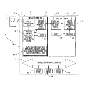
4 [0018] Referring initially to FIG. 1, a remote control system 10 for a
vehicle
illustratively includes a data communications bus 15 extending throughout the
vehicle
6 and connecting a plurality of vehicle devices 16a-16c within the vehicle
34. For
7 example, such vehicle devices 16a-16c may be associated with starter
motor relays,
8 headlight relays, sirens, the body control module, the engine control
module, the
9 powertrain control module, and/or one or more vehicle sensors. Those
skilled in the art
will recognize other vehicle devices that may be connected to the data bus 15.
11
12 [0019] The remote control system 10 illustratively includes a remote
transmitter 11 and
13 a vehicle controller 12 being responsive to the remote transmitter. The
remote
14 transmitter 11 may be a small portable unit including a housing,
function control
switches carried by the housing, a battery within the housing, and the
associated
16 transmitter circuitry. This type of remote handheld transmitter is
commonly used in
17 conventional vehicle security systems, remote start systems, and remote
keyless entry
18 systems. The communications from the remote transmitter 11 to the
vehicle controller
19 12 at the vehicle is typically a direct radio frequency link, that is,
there is no intervening
communications links. However, in other embodiments, the remote transmitter 11
may
21 indirectly communicate with the vehicle controller 12 via other
communications
22 infrastructure, such as via satellite, or cellular communications, via
the public switched
23 telephone network (PSTN) and/or over the world wide web or Internet, as
will be
24 appreciated by those skilled in the art.
26 [0020] The remote transmitter 11 may also include one or more central
station
27 transmitters, such as may be provided by a satellite transmitter or
cellular telephone
28 transmitter, for example. Such a central station transmitter may also be
connected to
29 other communications infrastructure as will be appreciated by those
skilled in the art.
6
23070546.1
CA 02921332 2017-01-30
CA 2,921,332
Blakes Ref: 11053/00007
1 [0021] The vehicle controller 12 includes controller circuitry carried by
a controller
2 housing 26. The controller circuitry includes a wireless communications
device 31 and
3 a processor 32 coupled thereto. The processor 32 is coupled to a
controller data link
4 interface 13 that, in turn, is connected to the data bus adaptor 14. A
vehicle controller
memory 18 is also coupled to the processor 32. Although the vehicle controller
memory
6 18 is illustrated as a separate device, those skilled in the art will
recognize that the
7 memory may alternatively be embedded on the same integrated circuit as
the
8 processing circuitry of the vehicle controller processor 32. The wireless
9 communications device 31 may include one or more transmitters and/or
receivers for
communicating at different frequencies, or different formats, for example.
11
12 [0022] Referring now to FIG. 2, in another embodiment, the vehicle
controller 12' may
13 also include a vehicle position determining device 41' coupled to the
processor 32'.
14 The processor 32' may cooperate with the vehicle position determining
device 41', for
example, a GPS receiver, and the wireless communications device 31' to
wirelessly
16 send vehicle position information. The vehicle position information may
be received by
17 a remote device remotely from the vehicle, for example, by a central
monitoring station
18 or mobile device (e.g., cellular telephone). The wireless communications
device 31'
19 may cooperate with the processor 32' to receive and process commands
from the
remote device, for example, to remotely control one of the vehicle devices
16a'-16c'.
21
22 [0023] Referring again to HG. 1, the vehicle controller 12, and more
particularly, the
23 vehicle controller processor 32 may be configured to cooperate with one
or more
24 vehicle devices 16a-16c to perform a vehicle starting function
responsive to the remote
transmitter 11. The vehicle controller 12 may also be also be for performing a
vehicle
26 security function such as arming a vehicle alarm system and/or a vehicle
convenience
27 function, for example, opening the windows or locking the doors. Of
course, the vehicle
28 controller 12 may perform other and/or additional functions.
29
7
23070546.1
CA 02921332 2017-01-30
CA 2,921,332
Blakes Ref: 11053/00007
1 [0024] The data bus adaptor 14 illustratively includes an adaptor housing
25 and
2 adaptor circuitry carried by the adaptor housing. The data bus adaptor
circuitry
3 illustratively includes a data bus adaptor processor 33 coupled between a
data adaptor
4 download interface 22 and an adaptor data link interface 21. The data bus
adaptor 14
is for adapting the vehicle controller 12 to communicate via the data
communications
6 bus 15. The adaptor data link interface 21 is coupled to the data bus
adaptor processor
7 33 and cooperates therewith to perform communication with the controller
data link
8 interface 13. More particularly, the adaptor link interface 21 cooperates
with the
9 controller data link interface 13 to provide a communication link for
adapting the vehicle
controller 12 to communicate with the vehicle devices 16a-16c via the data
11 communications bus 15.
12
13 [0025] Communication between the controller data link interface 13 and
the adaptor
14 data link interface 21 (i.e., the communication link) may be a serial
data
communications link. The serial data communications link is often a
proprietary digital
16 link for each manufacturer of the vehicle remote function controller.
The controller data
17 link interface 13 may be a wired controller data link interface, and the
adaptor data link
18 interface 21 may be a wired adaptor data link interface such that a
wired communication
19 link is established therebetween. In other embodiments, the controller
data link
interface 13 may be a wireless controller data link interface, and the adaptor
data link
21 interface 21 may be a wireless adaptor data link interface. Thus, a
wireless
22 communication link, such as a Bluetooth link, is established
therebetween. The vehicle
23 controller 12 is advantageously operable with a given set of adaptor
codes from among
24 different sets of adaptor codes for different adaptors 14 to thereby
provide compatibility
with different manufacturers.
26
27 [0026] The given set of adaptor codes is determined by an adaptor code
determining
28 circuit 36 of the vehicle controller 12. The adaptor code determining
circuit 36 is
29 coupled to the vehicle processor 32 and determines the given set of
adaptor codes
based upon communications with the data bus adaptor. For example, the adaptor
code
8
23070546.1
CA 02921332 2017-01-30
CA 2,921,332
Bakes Ref: 11053/00007
1 determining circuit 36 may determine the given set of adaptor codes from
one or more
2 codes received by the data bus adaptor. The given set of adaptor codes
may be stored
3 in the vehicle controller memory 18. For example, the adaptor code
determining circuit
4 36 and the vehicle controller processor 32 may cooperate to compare a
received data
bus adaptor code to those already stored in a look-up table in the vehicle
controller
6 memory 18 to thereby identify the particular manufacturer and/or code set
being used
7 by the data bus adaptor 14. Alternatively, the communication with data
bus adaptor 13
8 may include some other identifying code, voltage level, or other protocol
characteristic
9 that permits the adaptor code determining circuit 36 to determine the
proper code set.
While the adaptor code determining circuit 36 and the vehicle controller
processor 32
11 have been described as separate devices, it should be appreciated that
the functions of
12 the adaptor code determining circuit may be performed by the vehicle
controller
13 processor or be part of the same circuitry.
14
[0027] Turning now to another advantageous feature of the system 10, the
vehicle 34
16 may operate with a desired set of vehicle device codes from among a
plurality of
17 different sets of vehicle device codes for different vehicles. The
vehicle device codes
18 may be unique to each vehicle or vehicle manufacturer. Advantageously,
the data bus
19 adaptor 14 may include an adaptor download interface 22 for downloading
the given set
of the vehicle device codes. The adaptor download interface 22 may be wired or
21 wireless. The vehicle device codes may be downloaded prior to
installation in the
22 vehicle 34, for example.
23
24 [0028] Vehicle device codes from among a plurality of different sets of
vehicle device
codes for vehicles can be stored in a data bus adaptor memory 23 of the data
bus
26 adaptor 14. The memory 23 may be a plug-in IC, a PROM chip, a removable
FLASH
27 memory, or any other memory, as will be appreciated by those skilled in
the art.
28 Although the data bus adaptor memory 23 is illustrated as a separate
device, those
29 skilled in the art will recognized that the memory may alternately be
embedded on the
same integrated circuit as the processing circuitry of the data bus adaptor
processor 33.
9
23070546.1
CA 02921332 2017-01-30
CA 2,921,332
Blakes Ref: 11053/00007
2 [0029] Turning now additionally to the flowchart 100 of FIG. 3, a method
aspect is
3 described relating to operating the remote control system 10. After the
start at Block
4 102, codes, for example, adaptor codes are read or received from the data
bus adaptor
14 (Block 104). Based on the codes, a corresponding set of adaptor codes are
6 determined based upon the adaptor code determining circuit 36 (Block
106). For
7 example, the received code may be compared to sets of adaptor codes
stored in the
8 vehicle controller memory 18 to determine which set is to be used. The
vehicle
9 controller 12 operates the data bus adaptor 14 based using the given set
of adaptor
codes (Block 108). The method ends at Block 110
11
12 [0030] Many modifications and other embodiments of the invention will
come to the
13 mind of one skilled in the art having the benefit of the teachings
presented in the
14 foregoing descriptions and the associated drawings. Therefore, it is
understood that the
invention is not to be limited to the specific embodiments disclosed, and
that,
16 modifications and embodiments are intended to be included within the
scope of the
17 appended claims.
18
19
10
23070546.1