Note: Descriptions are shown in the official language in which they were submitted.
CA 02921419 2016-02-12
WO 2015/034757
PCT/US2014/053287
1
Construction for an Implantable Medical Device Employing an
Internal Support Structure
CROSS-REFERENCE TO RELATED APPLICATIONS
[0001] This
application is related to an application entitled "Construction for an
Implantable Medical Device Having a Battery Affixed to the Case," U.S.
Provisional Patent
Application Serial No. 61/874,197, filed September 5, 2013.
FIELD OF THE INVENTION
[0002] The
present invention relates to implantable medical devices, and more
particularly to an improved design and method of construction for an
implantable medical
device.
BACKGROUND
[0003]
Implantable stimulation devices deliver electrical stimuli to nerves and
tissues for
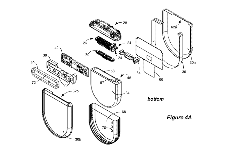
the therapy of various biological disorders, such as pacemakers to treat
cardiac arrhythmia,
defibrillators to treat cardiac fibrillation, cochlear stimulators to treat
deafness, retinal
stimulators to treat blindness, muscle stimulators to produce coordinated limb
movement,
spinal cord stimulators to treat chronic pain, cortical and deep brain
stimulators to treat motor
and psychological disorders, and other neural stimulators to treat urinary
incontinence, sleep
apnea, shoulder subluxation, etc. The description that follows will generally
focus on the use
of the invention within a Spinal Cord Stimulation (SCS) system, such as that
disclosed in
U.S. Patent 6,516,227. However, the present invention may find applicability
with any
implantable medical device or in any implantable medical device system.
[0004] A SCS
system typically includes an Implantable Pulse Generator (IPG) which has
a biocompatible device case formed of a conductive material such as titanium,
for example.
The case typically holds the circuitry of the IPG and a battery to provide
power to the
circuitry. Depending on the particular needs and circumstances of the patient
who will be
using the IPG, the battery can be either rechargeable or a non-rechargeable
primary battery.
[0005] Although
many IPGs use rechargeable batteries, there are situations in which use
of a primary battery may be advantageous. A primary battery is one in which
the
CA 02921419 2016-02-12
WO 2015/034757
PCT/US2014/053287
2
electrochemical reaction is not reversible by passing a charging current
therethrough, thus
rendering the battery non-rechargeable. Primary batteries use up the materials
in one or both
of their electrodes and thus have a limited life span, but they are typically
cheaper than
rechargeable batteries, and may not suffer from the same reliability concerns.
As such, the
use of primary batteries in a medical implantable device is preferred when
appropriate, for
example, when the expected life of the primary battery would be expected to
exceed the
patient's life expectancy, or in situations where patients with physical or
mental limitations
would have difficulty charging the battery. Use of a primary battery in an
IPG, however,
creates a challenge in the design and construction of the IPG, as a primary
battery is generally
larger in size than a rechargeable one, and it is not optimal to increase the
size of the IPG.
SUMMARY OF THE INVENTION
[0006] The
disclosed implantable medical device, in one example, includes a case; a
support structure within the case; an antenna within the case affixed to the
support structure;
a battery within the case affixed to the support structure; and a circuit
board within the case
affixed to the support structure, the circuit board comprising circuitry
configured to
implement the functionality of the implantable medical device. The antenna and
battery are
electrically coupled to the circuit board.
[0007] The
implantable medical device may comprise a primary battery, and the support
structure may comprises a single plastic piece. The battery may be affixed to
the support
structure by a first adhesive, and at a battery terminal face of the battery.
The support
structure may be affixed to the case using a second adhesive, and may be
affixed to only a
first side of the case. The battery may also be affixed to only the first side
of the case using
the second adhesive.
[0008] The
antenna in the implantable medical device may be recessed in the support
structure, and electrically coupled to the circuit board by pins passing
through the support
structure. The antenna may comprise a communication coil, a charging coil, or
a combined
communication and charging coil. The antenna and the circuit board may be
parallel and on
opposite sides of the support structure, and the battery may be affixed to the
support structure
at a battery terminal face of the battery, such that the battery terminal face
is perpendicular to
the antenna and the circuit board.
[0009] The
battery may occupy a first area within the case, while the combination of the
support structure, circuit board, and antenna together occupy a second non-
overlapping area
of the case. The battery may have a first thickness, while the combination of
the support
CA 02921419 2016-02-12
WO 2015/034757
PCT/US2014/053287
3
structure, circuit board, and antenna together comprise a second thickness
equal to or less
than the first thickness.
[0010] The
implantable medical device may also include a plurality of feedthrough pins
passing through the case, in which the feedthrough pins are electrically
coupled to the circuit
board, and in which the support structure comprises a sidewall gap for
accommodating the
plurality of feedthrough pins. At least one lead connector external to the
case may also be
included comprising a plurality of electrode contacts, with the feedthrough
pins electrically
coupled to the electrode contacts.
BRIEF DESCRIPTION OF THE DRAWINGS
[0011] Figure 1
shows an improved Implantable Pulse Generator (IPG) and the manner in
which electrode leads are affixed to the IPG.
[0012] Figure 2 shows bottom and top views of the improved IPG with its
case removed.
[0013] Figure 3
shows bottom and top perspective views of the improved IPG with its
case removed.
[0014] Figures
4A and 4B respectively show bottom and top perspective exploded views
of the components of the improved IPG.
[0015] Figure 5
shows bottom and top perspective views of a support structure used in
the improved IPG.
[0016] Figures
6A and 6B respectively show top and cross-sectional views of a
subassembly of the improved IPG at one stage of its construction.
[0017] Figure 7
shows positioning of a battery cover over the battery in the subassembly
at another stage of construction.
[0018] Figure 8
shows placement of glue drops on an IPG case portion corresponding to
locations of glue holes in the subassembly at another stage of construction.
[0019] Figure 9
shows affixing the subassembly to the case portion using the glue drops,
and encompassing the subassembly in the IPG case, at another stage of
construction.
[0020] Figure
10A shows cross sections of the completed IPG, and Figure 10B shows the
manner in which the glue drops adhere the battery and the support structure to
the case.
DETAILED DESCRIPTION
[0021] This
disclosure provides an improved design and method of construction for an
implantable medical device, and in particular an implantable medical device
having a larger
primary battery. However,
the design and method of construction are not limited to
CA 02921419 2016-02-12
WO 2015/034757
PCT/US2014/053287
4
implantable medical devices that use primary batteries, and can be used with
rechargeable-
battery IPGs as well. This improved design is easy to construct, mechanically
robust, and
uses few parts.
[0022] Figure 1
shows a SCS system having an IPG 10. The IPG 10 includes a
biocompatible device case 30 that holds the circuitry and battery 34 (Fig. 2)
necessary for the
IPG to function. The IPG 10 is coupled to electrodes 16 via one or more
electrode leads 14
that form an electrode array 12. The electrodes 16 are carried on a flexible
body 18, which
also houses the individual signal wires 20 coupled to each electrode. The
signal wires 20 are
connected to the IPG 10 at one or more lead connectors 24 fixed in a header
28, which can
comprise an epoxy for example. In the illustrated embodiment, there are
sixteen electrodes
split between two leads 14, although the number of leads and electrodes is
application
specific and therefore can vary. In a SCS application, electrode leads 14 are
typically
implanted on the right and left side of the dura within the patient's spinal
cord. The proximal
ends 22 of the leads 14 are then tunneled through the patient's flesh to a
distant location, such
as the buttocks, where the IPG case 30 is implanted, at which point they are
coupled to the
lead connector(s) 24.
[0023] Figures
2, 3, and 4A and 4B show various perspectives of the bottom side (the
side proximate a communication coil 40) and top side (the side proximate to a
printed circuit
board (PCB) 42) of the improved IPG 10. The case 30, which in the depicted
example is
formed as two case portions 30a and 30b, is removed in Figures 2 and 3 so that
certain
internal components can be seen, some of which are introduced now prior to
discussion of the
construction of the IPG 10.
[0024] As
shown, the majority of the room inside the case 30 is taken up by a battery 34
which, in this example, is a permanent, non-wirelessly-rechargeable battery.
The remainder
of the room in the case 30 is largely taken up by a support structure 38,
communication
antenna 40, which is this example comprises a coil, and a PCB 42. The
communication coil
40 enables communication between the IPG 10 and a device external to the
patient (not
shown), thus allowing bidirectional communication to occur by magnetic
induction. The
PCB 42 includes circuitry configured to implement the functionality of the
implantable
medical device. The lead connectors 24 are coupled to the PCB 42 by
feedthrough pins 48,
which proceed through a feedthrough 32 that is ultimately welded to the case
30 prior to
securing the header 28 to the IPG 10, as explained below. Suture holes 41 and
43 in the
header are used to suture the IPG to a patient's body during an operation.
CA 02921419 2016-02-12
WO 2015/034757
PCT/US2014/053287
[0025]
Construction of the IPG 10 begins with the discussion of the support structure
38,
which is shown in bottom and top perspective views in Figure 5. The support
structure 38
provides many benefits to the IPG 10. The support structure 38 comprises a
single piece for
receiving, holding, and protecting both the coil 40 and PCB 42. The coil 40,
PCB 42, and
battery 34 are affixed to the support structure 38, which integrates the
connections of these
components and results in a mechanically-robust IPG subassembly 92 (Fig. 6A)
resistant to
shock and vibration. Support structure 38 also provides electrical isolation
between the coil
40 and the PCB 42 (excepting the coil pins 44 explained below); between the
battery 34
(particularly, the positive terminal 46a of the battery 34) and the coil 40,
PCB 42, or
feedthrough pins 48; and between the feedthrough pins 48 and the coil 40, and
thus prevents
unwanted shorting of these components.
[0026] The
support structure 38 also provides one or more case contact surfaces 76 with
at least one glue hole 60 to allow the support structure 38, and hence the
already-robust IPG
subassembly 92, to be adhered to the case 30. The IPG subassembly 92 may
additionally be
adhered to the case 30 by the battery 34, as discussed below.
[0027] The
support structure 38 includes a recess 74 into which the coil 40 is affixed.
The coil 40 was earlier wound around a bobbin (not shown). The coil 40 is
preferably
recessed below the case contact surfaces 76 of the support structure 38 to
protect it and to
offset the coil 40 from the case 30 once the IPG 10 is constructed, as
discussed further below.
The ends of the coil 40 are soldered to coil pins 44 on the bottom side of the
support structure
38, which coil pins 44 pass through the support structure 38 and are
preferably molded into
the support structure 38 during its construction. Later in the construction
process, the other
(top) side of coil pins 44 will be soldered to the PCB 42 on the top side of
the support
structure 38 to electrically couple the coil to the electronics on the PCB 42
such as
modulation and/or demodulation circuitry. Coil 40 may be further affixed
within the recess
74 using an epoxy or other adhesive. Coil 40 may be covered with tape 72 as
shown to
electrically isolate the coil 40 from the feedthrough pins 48, which later
during construction
will be located within a gap 84 in a sidewall 80 of the support structure 38.
[0028] The
support structure 38 is preferably made of a material with high melting
temperature able to withstand soldering of the coil pins 44 to the coil 40 and
to other
structures as subsequently explained. The material for the support structure
38 is also
preferably mechanically rigid to provide mechanical robustness, and should
have a low
moisture content consistent with its use with electrical components and in an
implantable
medical device. In one embodiment, the material comprises a Liquid Crystal
Polymer (LCP).
CA 02921419 2016-02-12
WO 2015/034757
PCT/US2014/053287
6
[0029] Several
features of the support structure 38 that provide some of the benefits
discussed earlier are noticeable in Figure 5. For example, the top of the
support structure 38
includes support ribs 86 and mounting pins 88 that help to support and
position the PCB 42
that will be affixed to the support structure 38 later during construction.
The support
structure 38 also includes cavities 78, which provides space for taller
components on the PCB
42. The cavities 78 also help to define the recess 74 for the coil 40, and
provide two case
contact surfaces 76 with glue holes 60 on the bottom side of the support
structure 38, which
as already noted is useful in adhering the support structure to the IPG' s
case 30. The sidewall
80 of the support structure 38 again helps to define the recess 74 and isolate
the coil 40, and
additionally comprises a portion 82 to which the battery 34 will be affixed,
as explained later.
An isolation structure 90 and gap 83 in the sidewall will accommodate the
positive and
negative terminals 46a and 46b of the battery 34 later during construction.
Jig mounting
holes 106 can also be seen on the bottom of the support structure 38, whose
function is later
explained.
[0030] After
formation of the support structure 38, various pieces of the IPG 10¨for
example, the support structure 38, the PCB 42, the battery 34 and a lead
connector
subassembly 95 (explained below)¨can be electrically and mechanically attached
to form an
IPG subassembly 92, as shown in top and cross-sectional views of Figures 6A
and 6B.
[0031]
Construction begins by adhering double sided tape 58 to the face 57 of the
battery
34 that contains the battery terminals (Figs. 4A and 4B). The other side of
the double sided
tape 58 is adhered to the sidewall portion 82 of the support structure 38. As
noted earlier, the
support structure 38 preferably already contains the coil 40 pre-soldered to
the coil pins 44,
but the coil could also be affixed to the support structure at this time or
later during
construction, such as when soldering of components to the PCB 42 subsequently
occurs.
Because the case contact surfaces 76 on the bottom of the support structure 38
and the bottom
surface of the battery 34 are preferably planar, support structure 38 and
battery 34 can be
affixed with the double sided tape 58 by sliding them together on a flat
surface. It is not
strictly necessary to use double sided tape 58 to affix the battery 34 to the
support structure
38, and glue or other adhesives could be used as well.
[0032] The
terminals 46a and 46b of the battery 34 are bent at 90 degrees relative to the
flat battery terminal surface of the battery 34 and so are now pointing
upward, as best shown
in the top view of Figure 5. Notice in Figure 5 that the negative terminal 46b
passes through
the gap 83 in the sidewall 80 of the support structure 38, and that the
positive terminal 46a of
the battery 34 is at least partially surrounded by the isolation structure 90
formed in the
CA 02921419 2016-02-12
WO 2015/034757
PCT/US2014/053287
7
support structure 38. As such, the support structure 38, in addition to other
functions, serves
to isolate the positive battery terminal 46a from shorting to the negative
battery terminal 46b
and other components in the IPG 10, such as the coil 40 and the PCB 42.
Isolation structure
90 could be made in differing manners. The negative battery terminal 46b could
also be
isolated using an isolation structure 90.
[0033] Next,
the combined support structure 38 and battery 34 is placed in an assembly
jig 94 as shown in Figure 6B, which has recesses conforming to the shape of
these pieces it
receives to align and hold them during construction. As shown, the jig 94 can
have mounts
98 designed to mate with the jig mounting holes 106 on the bottom side of the
support
structure 38 to securely hold the combined support structure 38 and battery 34
in the jig 94.
Other means of support with the jig 94 could be used as well.
[0034] Next, a
lead connector subassembly 95 is positioned within the jig 94. The lead
connector subassembly 95 includes the lead connectors 24, the electrode
contacts 26, a carrier
64 (used to house and support the electrode contacts 26; see Figs. 4A and 4B),
the
feedthrough pins 48, and the feedthrough 32, and may be pre-formed prior to
this step in
construction. For example, lead connector subassembly 95 can be formed by
slipping the
feedthrough pins 48 through the feedthrough 32, soldering one end of the
feedthrough pins 48
to appropriate electrode contacts 26 in the lead connectors 24, and (if
necessary) soldering the
feedthrough pins 48 in the feedthrough 32 in a hermetic manner. Notice that
the free end of
the feedthrough pins 48 are bent at 90 degrees relative to the feedthrough 32
(as best seen in
Fig. 4B), and so when placed in the jig 94 are now pointing upward. Notice
also that the
feedthrough pins 48 will be positioned in the gap 84 in the sidewall 80 of the
support
structure 38 (Fig. 5), as discussed earlier.
[0035] Next,
the PCB 42¨preferably pre-fabricated with its electrical components¨is
affixed to the top side of the support structure 38. In this regard, PCB 42
includes coil solder
pin holes 50, battery terminal solder holes 52, feedthrough pin solder holes
54, and support
structure mounting holes 56, which are respectively slipped over and brought
into contact
with the upward-pointing coil pins 44, feedthrough pins 48, battery terminals
46a and 46b,
and mounting pins 88 of the support structure 38. Once the PCB 42 is slid over
these
structures, it comes to rest on the support ribs 86 (Fig. 5), which provides
suitable mechanical
support to keep the PCB 42 from flexing. The coil pins 44, feedthrough pins
48, battery
terminals 46a and 46b are then soldered to the coil solder pin holes 50,
feedthrough pin solder
holes 54, and battery terminal solder holes 52 respectively to electrically
couple them to the
PCB 42. The combined effect of the support ribs 86, mounting pins 88, and the
soldered
CA 02921419 2016-02-12
WO 2015/034757
PCT/US2014/053287
8
connections yields a PCB 42 that is firmly affixed to and protected by the
support structure
38 to complete the IPG subassembly 92. Although not shown, the PCB 42 can also
be
recessed in the support structure 38 to further electrically isolate it form
other structures and
for further mechanical protection.
[0036] Once IPG
subassembly 92 has been constructed, it is removed from the jig 94, and
a battery cover 68 is slipped over the battery 34, as shown in Figure 7. The
battery cover 68
typical comprises a thin plastic sleeve, and is used to electrically isolate
the battery 34's case
from the case 30 of the IPG 10, which may be at different potentials. The
battery cover 68
includes at least one battery cover glue hole 70 through which the battery 34
can be adhered
to the case 30 while still providing the desired electrical isolation.
[0037] The
battery cover 68 may completely surround the battery 34, but as shown it only
partially surrounds the battery 34, covering all surfaces of the battery 34
except the battery
terminal face 57. However, the battery cover 68 is not limited, and other
insulators may be
used as well. For example, an insulative coating might be provided on the case
of the battery
34, masked as necessary to form the glue holes 70 in the coating.
Alternatively an insulating
layer or sheet may be used that intervenes between the battery 34's case and
the IPG case 30
where they come into contact or are close to doing so. This alternative of use
of a single
insulting layer or sheet might be a good option for use in the IPG 10, because
as discussed
further below with respect to Figures 10A and 10B, the battery 34 is affixed
to the bottom
side of the case 30 and an air gap "x" exists between the battery and the top
side of the case,
and thus an insulator may not be necessary on this side as the battery 34 and
the case 30 are
less likely to short by virtue of this air gap. The battery cover 68 or other
insulator may also
cover other portions of the IPG subassembly 92, such as the support structure
to which the
coil 40 and the PCB 42 are affixed to also prevent these structures from
shorting to the case
30.
[0038] As shown
in Figure 8, glue drops 96 are placed at multiple locations inside the
bottom case portion 30b corresponding with the position of the support glue
holes 60 in the
support structure 38 and battery cover glue holes 70 in the battery cover 68.
The IPG
subassembly 92 is positioned in the bottom case portion 30b, as shown in
Figure 9, which
causes the glue drops 96 to penetrate through the glue holes 70 in the battery
cover 68 to
come in contact with the battery 34, and through the glue holes 60 in the
support structure 38,
as further discussed below with respect to Figure 10B. Alternatively, glue
drops 96 could be
placed on the IPG subassembly 92 at the holes 60 and 70, which is then
positioned in the
bottom case portion 30b. Glue drops 96 suitable for this application include
NuSi1TM Med3-
CA 02921419 2016-02-12
WO 2015/034757
PCT/US2014/053287
9
4213 silicone, but other types of glues or other adhesives may be used as
well. For example,
double sided tape could be used in place of glue drops 96. The adhesive used
at this step
could comprise the same adhesive (58) used to affix the battery 34 to the
support structure 38.
[0039] As
further shown in Figure 9, after the IPG subassembly 92 is affixed to the
bottom case portion 30b via the glue drops 92, the top case portion 30a is
positioned to
surround at least part of the IPG assembly 92 (but not lead connector
subassembly 95) in the
case portions 30a and 30b, and to meet the feedthrough 32 at cutouts 62a and
62b (Figs. 4A
and 4B) in the case portions 30a and 30b. (Note that an applicator 66 (Figs.
4A and 4B) is
used as an aid to properly align the case). The case portions 30a and 30b are
then preferably
laser welded together and laser welded to the feedthrough 32, although other
sealing methods
could be used, such as brazing, or the use of hermitic glues or other
adhesives.
[0040] Top and
bottom case portions 30a and 30b with parallel top and bottom sides are
not required, and instead the case 30 could comprise a uniform structure
generally resembling
a "cup" into which the subassembly 92 is placed and affixed. Such a cup-shaped
case may
also have parallel top and bottom sides. A cap, which may include the
feedthrough 32, can
then be welded to the open end of the cup.
[0041]
Thereafter, the epoxy header 28 (Fig. 1) is affixed to the case 30 around the
lead
connectors 24 and the feedthrough 32 to from a hermetic seal in standard
fashions, at which
point construction of the IPG 10 is complete.
[0042] Figure
10A shows a cross section of the fully constructed IPG 10, which allows
certain aspects and benefits of the design of the IPG to be appreciated. The
bottom side of
the battery 34 and the case contact surfaces 76 of the support structure 38
are planar and both
are affixed to the bottom case portion 30b as is preferable to add mechanical
robustness.
However, this is not strictly necessary, and instead only one of the battery
34 and support
structure 38 can be so affixed. Likewise, it is also not necessary that the
bottom sides of the
battery 34 and the case contact surfaces 76 of the support structure 38 are
planar. Note the
case contact surfaces 76 of the support structure 38 offset the coil 40 from
the bottom case
portion 30b to prevent short circuiting of the coil.
[0043] As
shown, the relatively-large primary battery 34 occupies first area 11 a in the
case 30, while the support structure 38, coil 40, and PCB 42 occupy a second
smaller area
llb in the case 30. The areas 11 a and 1 lb preferably do not overlap. This is
advantageous
because the support structure 38, coil 40, and PCB 42 do not require the
battery 34 to be
thinned, as would occur if these structures overlapped. Because
the battery 34 is not
constrained by the thickness of these structures, the thickness of the battery
34 is allowed to
CA 02921419 2016-02-12
WO 2015/034757
PCT/US2014/053287
substantially equal the thickness of the case 30 (e.g., within 15%). Coil 40
and PCB 42 are
parallel and overlap each other in the second area 1 lb, and are parallel to
the top and bottom
sides of the case 30, and perpendicular to the battery terminal face 57 of the
battery 34 and
feedthrough 32. As shown, the support structure 38, coil 40, and PCB 42 can
all be made to
fit equal to or less than the thickness of the battery 34, which again does
not constrain the
thickness that the battery 34 can have inside the case 30. Although, this is
not strictly
necessary.
[0044] A small
air gap "x" intervenes between the top side of the battery 34 and support
structure 38 and the top case portion 30a, which is useful to protecting the
battery 34 from
heat during welding of the two case portions 30a and 30b. As a further
protection against this
heat, a back-up band 36 (not shown in Fig. 3) can be provided around the
periphery of the
IPG assembly 92, as best shown in Figure 9. However, use of an air gap x is
not strictly
necessary. For example, the battery 34 could be affixed (e.g., glued) to both
the top and
bottom case portions 30a and 30b to leave no air gap, which would require
battery cover glue
holes 70 on both sides of the battery cover 68.
[0045] Figure
10B is magnified illustration of the glue holes 70 in the battery cover 68
and the glue holes 60 in the case contact surfaces 76. Preferably enough glue
96 is provided
to penetrate completely through the glue holes 60 to the other side of the
support structure 38,
thus creating a mushroom-shaped when dried, to anchor the support structure 38
to the
bottom side case portion 30b. This preference though is not strictly
necessary, and indeed the
case contacts surfaces 76 can be glued or affixed to the bottom case portion
30b even if holes
60 are not present.
[0046] Figure
10B also illustrates how glue 96 penetrates the glue holes 70 in the battery
cover 68 to adhere the battery 34 to the bottom case portion 30b. Glue holes
70 are
particularly advantageous in this case, because the material of the battery
cover 68 is
generally not suitable for adhesion. Because the material of the glue 96 is
insulative, the
battery 34 is affixed to the case 30 (despite the intervening battery cover
68) but is still
electrically insulated therefrom, which as noted earlier is desired because
they may be at
different potentials.
[0047] It
should be noted that the above construction steps are merely examples of how
the IPG 10 as designed can be constructed, and other manners are also
possible. For
example, construction steps can occur in different orders, or involve
different sub-steps or the
consolidation of steps.
CA 02921419 2016-02-12
WO 2015/034757
PCT/US2014/053287
11
[0048] While
the disclosed IPG design and method of construction were inspired by the
use of larger primary batteries, the disclosed design and methods could also
be used for an
IPG having a rechargeable battery. In such a case, the IPG might have an
additional antenna
(not shown), such as another coil to wirelessly receive a charging field that
is rectified to
charge the battery. Such additional charging coil, like communication coil 40,
could also be
affixed to the disclosed support structure 38. Alternatively, the disclosed
coil 40 could
comprise a combined communication/charging coil capable of performing both
communication and charging functions.
[0049] Although
particular embodiments of the present invention have been shown and
described, it should be understood that the above discussion is not intended
to limit the
present invention to these embodiments. It will be obvious to those skilled in
the art that
various changes and modifications may be made without departing from the
spirit and scope
of the present invention. Thus, the present invention is intended to cover
alternatives,
modifications, and equivalents that may fall within the spirit and scope of
the present
invention as defined by the claims.