Note: Descriptions are shown in the official language in which they were submitted.
SYSTEM FOR SEPARATING CONTAMINANTS FROM FLUIDS
BACKGROUND OF INVENTION
RELATED APPLICATIONS
[0001] This patent application claims the benefit of earlier filed US
Provisional
Patent Application No. 61/881,366 filed on September 23, 2013 and titled
SYSTEM FOR REMOVING CONTAMINANTS FROM WATER.
TECHNICAL FIELD
[0002] The present invention relates generally to filtration systems for
separating and removing contaminants from fluids.
BACKGROUND ART
[0003] Fluid is defined as a continuous, amorphous substance where
molecules move freely past one another and that has the tendency to
1
CA 2921434 2017-09-22
CA 02921434 2016-02-12
WO 2015/042443
PCT/US2014/056624
assume the shape of its container. Many substances are fluids including
but not limited to water. For purposes of this patent disclosure the fluid
is described as being water but it is to be expressly understood the
fluids described herein are not limited to water. Water at the molecular
level is formed of two Hydrogen (H) atoms bonded to one Oxygen (0)
atom. The chemical formula for water is H20. Water is one of the most
abundant substances on Earth and is essential for animal life and plant
life. Most life and particularly animal life requires water that is free from
contaminants and more particularly free from harmful contaminants.
There are a variety of known processes for separating contaminants from
water, and such processes may be as simple as a screen filter and as
complex as reverse osmosis. Generally it is the type of contaminant that
is to be removed from the water, and the subsequent use of the water
that dictates the complexity of the process used to remove the
contaminants. For example, if human consumption (potable water) is the
desired end product, the system/process must remove all harmful
2
CA 02921434 2016-02-12
WO 2015/042443
PCT/1jS2014/056624
contaminants and such systems can be both complex and expensive.
Conversely, if the desired end product is water suitable for industrial
purposes, the system may not need to be so complex, robust and
expensive.
[0004] One industrial process that produces large volumes of
contaminated fluid as a byproduct is induced hydraulic fracturing.
Induced hydraulic fracturing or hydro-fracturing, sometimes termed
"fracking", is a technique in which water is mixed with sand and
chemicals, and the mixture is injected at high-pressure into a well bore
to create small fractures (typically less than 1 mm), along which desirable
fluids including gas, petroleum and hydrocarbons may migrate to the
well for collection and harvesting.
[0005] The hydraulic fractures are created by pumping fracturing fluid
into the well bore at a rate sufficient to increase down-hole pressure
above the fracture gradient (pressure gradient) of the rock. The rock
cracks and the fracturing fluid continues propagating into the rock,
3
CA 02921434 2016-02-12
WO 2015/042443
PCT/1jS2014/056624
extending the crack still further. Introducing a proppant, such as grains
of sand, ceramic, or other particulates into the fracturing fluid prevents
the fractures from closing upon themselves when the pressure of the
fluid is removed.
[0006] During the fracturing process, some amount of fracturing fluid is
lost through "leak-off" when the fracturing fluid permeates into the
surrounding rock. If not adequately controlled, fracturing fluid leak off
can exceed 70% of the injected volume. The portion of the fracturing
fluid that is not lost through "leak off" returns to the surface through the
well and is called "waste water", "flow back water" or "produced water".
The waste water may be heavily contaminated.
[0007] Hydraulic fracturing equipment usually consists of a slurry
blender and one or more high-pressure high-volume fracturing pumps, a
monitoring unit and associated equipment including, but not limited to,
fracturing fluid tanks, units for the storage and handling of proppant, a
variety of testing, metering and flow rate equipment and storage tanks
4
CA 02921434 2016-02-12
WO 2015/042443
PCT/1jS2014/056624
and/or ponds for contaminated waste water. Typically, fracturing
equipment operates in high-pressure ranges up to approximately 15,000
psi and at volume rates of approximately 9.4 ft.3 per second. This is
approximately 100 barrels fluid per minute at 42 gallons per barrel.
(4200 gallons per minute).
[0008] The fracturing fluid injected into the well is typically a slurry of
water, proppants, poly-coagulants and chemical additives comprising
approximately 90% water, approximately 9.5% sand and approximately
0.5% chemical additives. A typical fracturing fluid composition, many of
which are proprietary and considered industrial trade secrets, uses
between three (3) and twelve (12) chemical additives which may include:
acids, sodium chloride, poly acrylamide, ethylene glycol, sodium
carbonate, potassium carbonate, flutaraldehyde, guar gum, citric acid
and isopropanol. Some portion
of the additives maybe charged
particulates and/or ionic molecules.
CA 02921434 2016-02-12
WO 2015/042443
PCT/1jS2014/056624
[0009] A typical fracturing process requires between approximately two
million and five million gallons of water per well. Approximately 10%-
40% of the fracturing fluid pumped into the well returns to the surface as
wastewater and commonly contains a variety of contaminants including,
but not limited to, hydrocarbons, carbon dioxide, hydrogen sulphide,
nitrogen, helium, iron, manganese, mercury, arsenic, lead, particulates,
chemicals and salts as well as the chemical additives added to the
fracturing fluid before injection into the well. Wastewater production
commonly averages between approximately 3,000 barrels and 5,000
barrels per day at 42 gallons per barrel. (126,000-210,000 gallons).
[0010] The wastewater flowing back to the surface and exiting the well
bore is collected and pumped into wastewater storage tanks or into
wastewater ponds that are lined with plastic or the like to prevent the
wastewater from leaching into the ground. After the fracking operation
is complete, the wastewater storage tanks and/or wastewater storage
6
CA 02921434 2016-02-12
WO 2015/042443
PCT/1jS2014/056624
ponds are drained and the wastewater therein is transported to salt water
dumps (SWDs) or hazardous waste sites for permanent disposal.
[0011] Beginning in 2015, a United States Government Environmental
Protection Agency (EPA) regulation will require a "paper-trail" that
documents when and where all hydraulic fracturing wastewater originates
and where the wastewater is taken for disposal. These new regulations
create additional expenses and increase future potential liabilities of
drillers and fracking operators.
[0012] In the Marcellus Shale deposit of North Dakota USA, it is
estimated to cost more than approximately $3 per barrel (42
gallons/158.98 liters) to dispose the wastewater and approximately $7 to
$10/per barrel (42 gallons/158.98 liters) to transport wastewater to an
approved disposal site. There is also a cost for sweet water (fresh water)
needed for conducting the hydraulic fracturing operation. In arid and
semi-arid areas fresh water is an additional cost factor. For example the
hydraulic fracturing of a horizontal well may use approximately 4.2
7
CA 02921434 2016-02-12
WO 2015/042443
PCT/1jS2014/056624
million gallons (15.89 million liters) of fresh water which must be
purchased and available for the fracking operation.
[0013] Fresh water sourcing is becoming a revenue business as some
municipalities and landowners in the Western United States are selling
water rights to the petroleum drilling industry for hydraulic fracturing.
[0014] For example, Texas has small amounts of available fresh water
but has the geography to properly dispose of contaminated wastewater.
Pennsylvania, on the other hand, has abundant supplies of fresh water
but has no place to dispose of wastewater. In the Northeast United
States, disposal of wastewater is problematic and as a result wastewater
disposal has moved generally West toward Ohio and Indiana and Virginia
where the wastewater is being dumped into pits. It is estimated in the
near future, wastewater "dumpers" may have to pay as much as
approximately $5,000 to $6,000 per truckload in disposal site charges
not including the cost of transporting the waste water to the dump site.
8
CA 02921434 2016-02-12
WO 2015/042443
PCT/1jS2014/056624
[0015] There are four primary methods for dealing with hydraulic
fracturing wastewater. A first method reuses the untreated wastewater in
the hydraulic fracturing process. Unfortunately, reuse is problematic as
high levels of contaminants tend to plug the well with "residual
chemicals", particulates, or shale fines" which may negatively impact
production of the well.
[0016] A second method is "deep well injection," which entails drilling a
deep disposal well into which the wastewater is pumped for permanent
disposal. Deep well injection is problematic as seismologists and the
scientific community have alleged earthquakes "were almost certainly
induced by the disposal of fracking wastewater in deep disposal wells."
The drilling of a disposal well is also expensive and such disposal
increases the volume of fresh water required for fracturing operations as
the wastewater is not re-used.
[0017] A third method is on-site treatment of the wastewater which
removes the most harmful chemicals and contaminants from the
9
CA 02921434 2016-02-12
WO 2015/042443 PCT/1jS2014/056624
wastewater. Some portion of the treated water may then be reused in the
fracturing. On-site treatment generally has negligible transportation
costs, but with known systems and known technology is more expensive
than other options due to the high maintenance costs of know systems
and the need to repeatedly shut the system down for cleaning and
backwashing. Further, such known systems and technology operate
under high pressures typically exceeding 250 psi, are readily known for
being easily damaged and even destroyed by small amounts of
hydrocarbons that may accidentally pass through the system to filter
membranes. Such filter membranes have a limited amount of membrane
surface area available for filtration, are expensive, and difficult to
replace. Further, membrane replacement is a time consuming process
during which the system must be shut down.
[0018] The fourth method is off-site treatment and disposal of the
wastewater. Similar to deep well
injection, off site treatment and
disposal increases the volume of fresh water required for fracturing
CA 02921434 2016-02-12
WO 2015/042443
PCT/1jS2014/056624
operations as the wastewater is not reused or recycled. This fourth
option is the most expensive as transportation costs and disposal costs
may be enormous.
[0019] One industry estimate places the cost of treating wastewater,
including costs for equipment, operation, labor, chemicals, and sludge
handling, at up to approximately $20 per barrel. Because hydraulic
fracturing may produce upwards of 3,000-5,000 barrels (126,000 -
210,000 gallons, or 476,961 -794,936 liters) of wastewater per well, per
day, this cost may be as high as $60,000-$100,000 per day.
[0020] The huge volume of fresh water necessary for fracturing
operations, many of which occur in arid and semiarid areas, is another
significant cost that must be recouped. Any ability to reuse or recycle
wastewater can offset some portion of the cost. Water, be it the
acquisition of fresh water, the handling of the wastewater, and the
ultimate disposal of the wastewater is a significant and burdensome cost
that is necessarily borne in the cost of the well. Further, because the
CA 02921434 2016-02-12
WO 2015/042443
PCT/1jS2014/056624
wastewater may be so contaminated with pollutants, chemicals, salts and
the like, the wastewater may be characterized as "hazardous waste" that
must be inventoried, tracked, and handled with extreme care prior to,
during and after disposal. Further, disposal of "hazardous waste" leads
to more hazardous waste sites that permanently damage the
environment.
[0021] Any means by which wastewater may be filtered or otherwise
treated to remove contaminants and allow reuse and/or recycling of the
water, or disposal of the water in sites other than "hazardous waste sites"
or "saltwater dumps" will reduce the cost of bringing wells into
production and will reduce the hazardous byproducts and environmental
impacts of hydraulic fracturing operations.
[0022] The instant invention resolves various of these known problems
by providing a mobile truck mounted system comprising a combination
of known and new filtration and separator technology and salt removal
technology for wastewater generated as a byproduct of hydraulic
12
CA 02921434 2016-02-12
WO 2015/042443
PCT/1jS2014/056624
fracturing operations, wastewater from industrial processes and
wastewater from agricultural operations, including, but not limited to
feedlots.
[0023] The instant invention allows the wastewater to be recycled for
re-use by separating and removing contaminants in a series of steps
which provides savings by reducing the need for fresh water and
reducing costs of transportation to and from fresh water sources,
reducing the need to transport wastewater to dump sites, reduction in
dump fees and by reducing the amount of wastewater that requires
governmental regulated disposal.
[0024] The removal of contaminants, including but not limited to solids,
oils, BTEX compounds, diesel, benzene, toluene, xylene, ethyl-benzene,
distillates, dissolved salts, phosphates, iron, manganese, arsenic, poly-
coagulants, fertilizers and animal waste is achieved through use of the
instant inventor system.
13
CA 02921434 2016-02-12
WO 2015/042443
PCT/1jS2014/056624
[0025] The instant contaminant removal system is modular and is
carried on trailers allowing the entire system to be mobile. The kilowatt
(KW) requirement for the complete system is approximately 500KW which
may be supplied by portable skid mounted generator sets.
[0026] The performance of the instant system for removal of
contaminants and recovery of the fluid is between approximately 350
gallons per minute (GPM) and approximately 450 GPM.
[0027] The instant system for separating contaminants from fluid
removes even small amounts of oil that destroy Poly-Pan filtration
membranes of salt removal systems which are costly to repair, replace
and maintain.
[0028] Some or all of the problems, difficulties and drawbacks
identified above and other problems, difficulties, and drawbacks may be
helped or solved by the inventions shown and described herein. The
instant invention may also be used to address other problems,
difficulties, and drawbacks not set out above or which are only
14
CA 02921434 2016-02-12
WO 2015/042443
PCT/1JS2014/056624
understood or appreciated at a later time. The future may also bring to
light currently unknown or unrecognized benefits which may be
appreciated, or more fully appreciated, in the future associated with the
novel inventions shown and described herein.
CA 02921434 2016-02-12
WO 2015/042443
PCT/1jS2014/056624
BRIEF SUMMARY OF THE INVENTION
[0029] A system for
separating contaminants from fluids provides a
modular continuously operable mobile system having an oil-water
separator, an optimizer, a dwell tank, a waste tank, a first particulate
filter, a parallel second particulate filter, a first step down membrane
filter, a parallel second step down membrane filter, a mixing station, a
sensor array and a totalizer. An ultra-
filtration system, a reverse
osmosis filter and a chemical blender may be optionally added to the
system to further contaminant removal.
[0030] In providing such a system for the separation of contaminants
from fluids it is:
[0031] a principal object to provide a modular mobile system that is
continuously operable even when components are being backwashed.
[0032] a further object to provide a modular mobile system that
removes hydrocarbons.
16
CA 02921434 2016-02-12
WO 2015/042443
PCT/1jS2014/056624
[0033] a further object to provide a modular mobile system that
provides a means for blending treated/filtered fluid with water to attain
the desired standards.
[0034] a further object to provide a modular mobile system that will
process acids and alkaline fluid through pH neutralization and balancing
to attain desired standards.
[0035] a further object to provide a modular mobile system that
provides an adjustable bypass where 100% of the fluid need not pass
through the entire system.
[0036] a further object to provide a modular mobile system that allows
the pH to be adjusted to desired standards to facilitate effective
flocculation, coagulation, precipitation and contaminant
se paration/ removal.
[0037] a further object to provide a modular mobile system that
separates/removes micron size contaminants.
17
CA 02921434 2016-02-12
WO 2015/042443
PCT/1jS2014/056624
[0038] a further object to provide a modular mobile system that
provides a variety of sensors and gauges to monitor head pressure, flow
rate, flow volume and system performance.
[0039] a further object to provide a modular mobile system having
parallel filter paths for continuous operation.
[0040] a further object to provide a modular mobile system that
operates at low-pressure of approximately between 60 PSI and 100 PSI.
[0041] a further object to provide a modular mobile system that utilizes
magnetic fields and electric fields between filter elements to exert ionic
influences on charged and ionic particulates.
[0042] a further object to provide a modular mobile system that uses
low pressure membranes to separate contaminants from fluids.
[0043] a further object to provide a modular mobile system that uses a
''step down" process through plural fluidically interconnected bodies to
facilitate continuous operation using membrane filters.
18
CA 02921434 2016-02-12
WO 2015/042443
PCT/1jS2014/056624
[0044] a further object to provide a modular mobile system having an
optional ultra filtration manifold using replaceable filter cartridges.
[0045] a further object to provide a modular mobile system having an
optional chemical blender to modify, buffer and pH balance the fluids.
[0046] a further object to provide a modular mobile system having an
optional reverse osmosis filter.
[0047] a further object to provide a modular mobile system that
provides an optional dwell tank to facilitate flocculation, precipitation
and settling of contaminants and particulates.
[0048] a further object to provide a modular mobile system having a
chemical meter for precisely metering additives into the fluids to
facilitate and promote flocculation, coagulation, settling and precipitation
and contaminant removal.
[0049] a further object to provide a modular mobile system that
oxygenates fluids.
19
CA 02921434 2016-02-12
WO 2015/042443
PCT/1jS2014/056624
[0050] a further object to provide a modular mobile system that
supplies ozone to the fluids.
[0051] a further object to provide a modular mobile system having
filtration vessels that utilize a variety of filter medias.
[0052] a further object to provide a modular mobile system having
filtration vessels that utilize crushed glass filter media.
[0053] a further object to provide a modular mobile system having
filtration vessels that utilize IMA-65 as a filter media.
[0054] a further object to provide a modular mobile system that
provides for continuous and "on demand" addition of chemicals to
enhance and facilitate separation of contaminants and coagulation and
precipitation of contaminants.
[0055] a further object to provide a modular mobile system having
easily replaceable membrane filters.
[0056] a further object to provide a modular mobile system having
variable membrane filter surface area.
CA 02921434 2016-02-12
WO 2015/042443
PCT/1jS2014/056624
[0057] a further object to provide a modular mobile system having a
magnetic field and an electric field to exert magnetic field and electric
field influences on charged and ionic particles within the fluids.
[0058] a still further object to provide a modular mobile system that
provides a means to heat the fluid.
[0059] Other and further objects of the instant system for separating
contaminants from fluids will appear from the following specification and
accompanying drawings which form a part hereof. In carrying out the
objects of the invention it is to be understood that its structures and
features and steps are susceptible to change in design and arrangement
and order with only one preferred and practical embodiment of the best
known mode being illustrated in the accompanying drawings and
specified as is required.
21
CA 02921434 2016-02-12
WO 2015/042443
PCT/1jS2014/056624
BRIEF DESCRIPTION OF THE DRAWINGS
[0060] Preferred forms, configurations, embodiments and/or diagrams
relating to and helping to describe preferred aspects and versions of my
invention are explained and characterized herein, often with reference to
the accompanying drawings. The drawings and features shown herein
also serve as part of the disclosure of my invention, whether described in
text or merely by graphical disclosure alone. The drawings are briefly
described below.
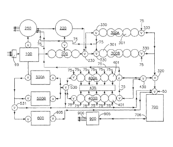
[0061] Figure 1 is a block diagram of the instant inventive system for
separating contaminants from fluids showing the relationship of the
various components with fluid flow thereth rough indicated by arrows.
[0062] Figure 2 is an orthographic cross section of an oil water
separator with arrows showing the direction of fluid flow therethrough.
22
CA 02921434 2016-02-12
WO 2015/042443
PCT/1jS2014/056624
[0063] Figure 3 is an orthographic partial cutaway side view of one
optimizer body with arrows showing the direction of fluid flow
thereth rough.
[0064] Figure 4 is an orthographic partial cutaway side view of one
particulate filter showing the filter medias therein with arrows showing
the direction of fluid flow therethrough.
[0065] Figure 5 is an orthographic partial cutaway side view of a step
down membrane filter showing a membrane filter cartridge therein with
arrows showing the direction of fluid flow therethrough.
[0066] Figure 6 is an exploded orthographic side view of a membrane
filter cartridge.
[0067] Figure 7 is an orthographic plan view of an optional ultra-
filtration manifold carrying plural screw on filter cartridges.
[0068] Figure 8 is an orthographic partial cross section view of an ultra
filtration canister carrying a paper filter cartridge therein taken on line 8-
8 of Figure 7.
23
CA 02921434 2016-02-12
WO 2015/042443
PCT/1jS2014/056624
[0069] Figure 9 is an orthographic cross section view of an optional
reverse osmosis filter.
[0070] Figure 10 is an orthographic partial cutaway side view of a dwell
tank with arrows showing the direction of fluid flow therethrough.
[0071] Figure 11 is an orthographic partial cutaway side view of a waste
tank.
24
DETAILED WRITTEN DESCRIPTION
Introductory Notes
[0072] The readers of this document should understand that dictionaries were
used in the preparation of this document. Widely known and used in the
preparation hereof are The American Heritage Dictionary, (4th Edition 2000),
Webster's New International Dictionary, Unabridged, (Second Edition 1957),
Webster's Third New International Dictionary, (0 1993), The Oxford English
Dictionary (Second Edition 1989), and The New Century Dictionary, ( 2001-
2005), all of which are to be referred to for interpretation of terms used
herein,
and for application and use of words defined in such references to more
adequately or aptly describe various features, aspects and concepts shown or
otherwise described herein using words having meanings applicable to such
features, aspects and concepts.
CA 2921434 2017-09-22
[0073] This document is premised upon using one or more terms with one
embodiment that may also apply to other embodiments for similar structures,
functions, features and aspects of the inventions. Wording used in the claims
is also descriptive of the inventions, and the claims should be given the
broadest interpretation consistent with the description as a whole.
[0074] The readers of this document should further understand that the
embodiments described herein may rely on terminology and features used in
any section or embodiment shown in this document and other terms readily
apparent from the drawings and language common or proper therefore. This
document is premised upon using one or more terms or features shown in
one embodiment that may also apply to or be combined with other
embodiments for similar structures, functions, features and aspects of the
inventions and provide additional embodiments of the inventions.
26
CA 2921434 2017-09-22
CA 02921434 2016-02-12
WO 2015/042443
PCT/1jS2014/056624
[0075] As used herein, the term "bottom" and its grammatical
equivalents means that portion of the system for removing contaminants
from fluids, or a component thereof, that is closest to a supporting
ground surface. The term "top" and its grammatical equivalents means
that portion of the system for removing contaminants from fluid, or a
component thereof, that is vertically distal from the supporting ground
surface.
[0076] A system for
separating contaminants from fluids generally
provides a modular mobile continuously operable multistage system
having an oil water separator 100, an optimizer 200, a dwell tank 220, a
waste tank 250, a particulate filter 300, a step down membrane filter
400, a mixing station 700 and a totalizer 900. Optionally, the system for
system contaminants from fluids may also provide an ultra filtration
system 500, a reverse osmosis filter 600 and a chemical blender 800.
[0077] In a most simple description, the instant system takes
contaminated fluid, such as but not limited to waste water from induced
27
CA 02921434 2016-02-12
WO 2015/042443
PCT/1jS2014/056624
hydraulic fracturing operations and/or waste water from agricultural
operations, or juice from fruit/vegetable pulping as an input, separates
contaminants from the fluid through multiple stages of coagulation,
precipitation and filtering and produces as an output, a fluid that is
reusable, and separated concentrated contaminants that are graduated
by particle site. The system is economical, continuously operable, is
modular and is mobile.
[0078] The oil-water separator 100, which may be a vertical tube
coalescing filter, or a gravimetric API filter, or a parallel plate separator
operating on the principals of specific gravity and Stokes Law is similar to
an oil-water separator manufactured by Oil Water Separator
Technologies, LLC of Florida USA. In the preferred embodiment the oil-
water separator 100 is a parallel plate separator. The oil-water separator
100 (Figure 2) comprises a body 101 defining an interior volume 102
carrying plural parallel angulated separator plates 108 therein. The body
101 defines a fluid inlet 103 at a one end portion through which
28
CA 02921434 2016-02-12
WO 2015/042443
PCT/1jS2014/056624
contaminated fluid enters the volume 102. A sludge catch basin 104 is
within the volume 102 proximate a bottom portion of the body 101.
Sludge drains 105 defined in the body 101 provide a means for removing
sludge and the like from the volume 102. A rotary skimmer 106 is
carried within the volume 102 proximate a top portion and spaced apart
from the fluid input 103. The rotary skimmer 106 rotates on an elongate
axis and removes contaminants agglomerating on an upper surface of
fluid within the volume 102. The plural parallel angulated plates 108 are
carried within the volume 102 spacedly below the rotary skimmer 106.
Contaminants such as oil agglomerate on bottom surfaces of the plural
parallel angulated plates 108. As the agglomerations of oil become
larger the agglomerations tend to move upwardly along the bottom
surface of the plural parallel angulated separator plates 108 and
ultimately "float free" from the plural parallel angulated separator plates
108 to rise to the surface of the fluid within the volume 102 to be
removed by the rotary skimmer 106. Sediments within the fluid fall onto
29
CA 02921434 2016-02-12
WO 2015/042443
PCT/1jS2014/056624
top surfaces of the plural parallel angulated separator plates 108 and
collect in the sludge basin 104. Adjustable wire plates 110 allow the
fluid levels to be adjusted as needed to promote contaminant removal. A
fluid outflow 109 is defined in the body 101 distal from the fluid input
103.
[0079] In the preferred embodiment, the oil-water separator 100 is
trailer mounted and is mobile. The oil water separator 100 fluidically
and electrically interconnects with the other components of the system
by known plumbing and electrical interconnections and apparatus. From
the oil water separator 100 the fluid flows through the fluid outflow 109
to the optimizer 200.
[0080] The optimizer 200 (Figures 1 and 3) comprises plural bodies
201 fluidically communicating with one another by known plumbing
apparatus. Each body 201 has a top 202, a bottom 203, a side portion
204 extending from the top 202 to the bottom 203 and defines an
interior volume 205. An inflow port 206 defined in the side portion 204
CA 02921434 2016-02-12
WO 2015/042443
PCT/1jS2014/056624
generally medially between the top 202 and bottom 203 communicates
with the interior volume 205 and allows fluids from the oil-water
separator 100 to flow into the volume 205. An outflow port 208 is
defined in the side portion 204 of each body 201 preferably at a position
vertically above the inflow port 206. A chemical input port 209
communicating with the volume 205 is defined in a top portion 202 of
each body 201. A chemical additives meter 214 communicates with the
chemical input port 209 to add/meter into the interior volume 205
precise amounts of chemical additives, such as but not limited to, pH
buffers, acids, bases, flocculants, poly-coagulants and the like which
may enhance coagulation and precipitation of contaminants within the
fluid.
[0081] The chemical additive meter 214 will automatically or manually
add various types of coagulants and/or other chemical additives to the
fluid within the optimizer 200. Coagulants (not shown) added to the
fluid within the optimizer 200 causes contaminants and small
31
CA 02921434 2016-02-12
WO 2015/042443
PCT/1jS2014/056624
particulates within the fluid to coagulate together and form floccules
which are more readily filtered from the fluid. A solids draw off port 207
is defined proximate the bottom 203 of the optimizer 200 to allow
coagulated and/or precipitated solids to be removed from the volume
205.
[0082] Heater 210 communicates with each body 201 proximate the
bottom 203 to heat fluid within each body 201 to a desired optimal
temperature for coagulation and precipitation. It is
anticipated the
heater would be electrically powered using heating elements (not shown)
but it is also possible the heater may be operated by other known means.
A diffuser plate 211 defining a plurality through holes therein is carried
within the interior volume 205 spaced above the bottom 203 and an air
input port 212 and an ozone input port 213 is defined in the body 201
below the diffuser plate 211 to allow air and/or ozone to be injected into
the interior volume 205 creating a plurality of bubbles to "bubble up"
through the diffuser plate 211 and the fluid within the interior volume
32
CA 02921434 2016-02-12
WO 2015/042443
PCT/1jS2014/056624
205 to enhance coagulation and precipitation of contaminants. The
addition of ozone to the fluid within the interior volume 205 provides the
added benefit of rapidly oxidizing a variety of chemicals and
contaminants and also killing various bacteria, algae and molds that may
be present in the contaminated fluid. The use of ozone reduces the need
for adding biocides and similar chemicals to kill plants and organisms
within the fluid.
[0083] A pump 215 communicates with plumbing means to move fluid
into and out of the interior volume 205 of each body 201. As shown in
Figure 1 plural bodies 201 are interconnected to provide an efficient
optimizer 200 that provides adequate time for metered-in chemical
additives, pH balancers, coagulants and the like to react with the fluid.
[0084] An optional dwell tank 220 (Figure 10) fluidically communicates
with the optimizer 200 and provides a location where the fluid, which has
had pH buffers, chemical additives, flocculent, precipitates, acids, bases
and the like added thereto may "rest" while precipitates "fallout'' of the
33
CA 02921434 2016-02-12
WO 2015/042443
PCT/1jS2014/056624
fluid column therein. The dwell tank 220 is preferably a generally
cylindrical and mobile tank having a top 221, a bottom 222, a side
portion 223 extending from the top 221 to the bottom 222 and defines
an interior volume 224. Inflow port 225 is defined in the dwell tank 220
spacedly between the top 221 and the bottom 222. An outflow port 226
is defined in the side portion 223 preferably at a position vertically above
the inflow port 225 so that precipitates and solids "falling out or
otherwise precipitating in the fluid column within the interior volume 224
may settle to the bottom 222 and not flow outwardly from the interior
volume 224 when the fluid is removed from the dwell tank 220. The
treated fluid within the dwell tank 220 is moved into the dwell tank 220,
and out of the dwell tank 220, by means of pump 215 and valves
communicating with known plumbing means.
[0085] A waste tank 250 (Figure 11) has a top 251, a bottom 252, a
side portion 253 extending from the top 251 to the bottom 252 and
defines an interior volume 254. An inflow port 255 communicates with
34
CA 02921434 2016-02-12
WO 2015/042443
PCT/1jS2014/056624
the interior volume 254 and provides an access through which waste,
sludge and the like may be deposited in the waste tank 250 interior
volume 254. An outflow port 256 is defined in the waste tank 250
proximate the bottom 252 and provides a means for draining, or
otherwise removing waste from within the interior volume 254. The
waste tank 250 fluidically communicates with the oil-water separator
100, with the optimizer 200, with the dwell tank 220 by means of known
plumbing interconnections and pumps and valves. The waste tank 250
provides a secure and safe location for storage of hazardous chemicals
and waste products filtered out of the fluid passing through the instant
system for removing contaminants from fluids. It is anticipated waste
collected within the waste tank 250 would be transported, on an as
needed basis, to a hazardous waste site, or other approved disposal site
for waste chemicals. The waste tank 250, because it defines a
completely enclosed volume 204 prevents evaporation and volatization
CA 02921434 2016-02-12
WO 2015/042443
PCT/1jS2014/056624
of chemicals and additives therein and also protects the environment,
wildlife and surroundings.
[0086] The outflow port 208 defined in the optimizer 200, and the
outflow port 226 defined in the dwell tank 220 each communicate with a
selector valve 230 for directing the fluid from the optimizer 200 to the
particulate filter 300 and fluid from the dwell tank 220 to the particulate
filter 300.
[0087] The particulate filter 300 (Figures 1 and 4) has two parallel filter
assemblies which are herein referred to as a first particulate filter 300A
and a parallel second particulate filter 300B. Fluids to be filtered may
flow through either the first particulate filter 300A, or through the
parallel second particulate filter 30013 or through both particulate filters
300A, 30013 by operation valve 230. Because the particular filters 300A,
30013 are similar to one another, only the first particulate filter 300A will
be described in detail herein.
36
CA 02921434 2016-02-12
WO 2015/042443
PCT/1jS2014/056624
[0088] The particular filter 300 comprises plural fluidically
interconnected filter bodies 301, each having a top 302, a bottom 303
and a side portion 304 extending from the top 302 to the bottom 303.
Each body 301 defines an interior volume 305. In the
preferred
embodiment, each body 301 is an approximately sixty inch (152.4 cm)
diameter "vertical barrel type" filter canister such as those made by
Yardney , Inc. of California USA. The bodies
301 are fluidically
interconnected with one another by known plumbing apparatus and
connections.
[0089] Each body 301 (Figure 4) defines an inflow port 306 and a
spaced apart outflow port 307. The interior volume 305 of each filter
body 301 contains plural filter medias preferably a first filter media 310,
a second filter media 311, a third filter media 312, and a fourth filter
media 313. Each filter media 310, 311, 312, 313 is particulated and the
particulates have different sizes and different weights so that the filter
medias 310, 311, 312, 313 vertically stack automatically - by gravity due
37
CA 02921434 2016-02-12
WO 2015/042443
PCT/1jS2014/056624
to weight - and will generally "re-stack" automatically subsequent to any
backwash cleaning process.
[0090] The first filter media 310 is preferably particulated small
diameter anthracite coal and the particulates thereof form a first upper
most layer within the filter body 301 and is between approximately 3
inches (7.5 cm) in depth and 18 inches (46 cm) in depth. The anthracite
coal particles preferably have a particle size of approximately between
0.5mm to 1.15mm in diameter.
[0091] The second filter media 311 positioned vertically below the first
media 310 is preferably particulated garnet and the particulates are
preferably approximately 0.25mm to 0.5mm in diameter. Because the
particulated garnet is heavier than the anthracite coal it creates a
"medial'' layer within the filter body 301 and is between approximately 3
inches (7.5 cm) in depth and 18 inches (46 cm) in depth.
[0092] The third filter media 312 is preferably either particulated garnet
or silica having an average particulate size of approximately between
38
CA 02921434 2016-02-12
WO 2015/042443
PCT/1jS2014/056624
1.15mm to 2.0mm in diameter. Because the particulates of the third
filter media 312 are larger than those of the second filter media 311 the
third media particulates 312 will tend to stack vertically below the second
filter media 311. The third filter media 312 preferably has a depth of
between approximately 6 inches (15cm) and 36 inches (92 cm).
[0093] The fourth filter media 313 is preferably particulated rock, the
particulates having an average particulate size of approximately between
0.3 inches (0.7 cm) and 0.85 inches (2.2 cm) in diameter. The fourth
filter media 313 is the bottom layer of the filter medias 310, 311, 312,
313 within the filter body 301 and preferably has a depth of between
approximately 6 inches (15 cm) and 36 inches (92 cm) inside the volume
305 of the filter body 301. A septum (not shown) or other known
apparatus retains the filter medias 310, 311, 312, 313 within the volume
305 and prevents the filter medias 310, 311, 312, 313 from passing
through the outflow port 307 during filtration.
39
CA 02921434 2016-02-12
WO 2015/042443
PCT/1jS2014/056624
[0094] In a second preferred embodiment, at least one of filter medias
310, 311, 312, 313 is crushed glass. The use of crushed glass as a
particulated filtration media 310, 311, 312, 313 allows filtration of
smaller/finer particles from the fluid due to the configurations and edge
portions of the glass particles. Use of crushed glass as the filter media
allows the instant system for removing contaminants from fluids to
remove particles down to approximately 8 microns in size.
[0095] In a still further preferred embodiment, at least one of filter
medias 310, 311, 312, 313 is a filter media commercially known as IMA-
65" which is manufactured by YardneyTm Water Filtration Systems of
Riverside CA, USA. IMA-65 has a unique property of chemically reacting
with contaminants such as, but not limited to, Iron (Fe), and Manganese
(Mg), and Arsenic (Ar), and is effective in removing these and other
contaminants from the fluid. Further, IMA-65 reduces and/or eliminates
the necessity of adding potassium permanganate into the fluid stream to
cause effective coagulation, precipitation and filtration. In place of the
CA 02921434 2016-02-12
WO 2015/042443
PCT/1jS2014/056624
added potassium permanganate, use of IMA-65 as a filtration media 310,
311, 312, 313 allows small amounts of chlorine (Cl) to be used in place
of the potassium permanganate.
[0096] The plural filter bodies 301 are interconnected to one another in
parallel by known plumbing apparatus and fittings so that inflow of fluid
enters the inflow ports 306 of each of the plural bodies 301 generally
simultaneously and percolates through the filter medias 310, 311, 312,
313 and exits the outflow ports 307 generally simultaneously. Known
plumbing connections communicating with the outflow ports 307
thereafter communicate with selector valves 330 that may be actuated to
initiate backwash cleaning operations.
[0097] A variety of sensors (not shown) and gauges (not shown)
communicate with the volume 305 inflow port 306 and outflow port 307
of each body 301 to monitor head pressure, flow rates and conditions
within the volumes 305. Any increase in "head pressure" or decrease in
flow rate is indicative of the filter medias 310, 311, 312, 313 becoming
41
CA 02921434 2016-02-12
WO 2015/042443
PCT/1jS2014/056624
saturated or otherwise plugged with contaminants such that fluid
passage therethrough is reduced. When saturation or "plugging" occurs,
selector valve 230 may be manually or automatically activated which
directs the fluid input from the optimizer 200 and/or dwell tank 220 to
flow through known plumbing connections into the parallel second
particulate filter 3008 to maintain continuous filtration operations. While
the fluid is being filtered by the parallel second particulate filter 3003,
the first particulate filter 300A may be backwashed by forcing clean
water through valve 330 and through backwash in flow port 308 and
through the filter medias 310, 311, 312, 313 in a reverse direction which
causes the accumulated contaminants within the filter medias 310, 311,
312, 313 to flow outwardly through a backwash outflow port 309
whereupon the out flowing contaminants may be fluidically directed to
the waste tank 250 for collection, storage and ultimate disposal.
Depending upon the type of contaminants and/or particulates being
removed it may be desirable to direct the backwash from the particulate
42
CA 02921434 2016-02-12
WO 2015/042443
PCT/1jS2014/056624
filter 300 in to the optimizer 200 for further precipitation of particulates
in order to further save volumes of fluid.
[0098] The backwash cleaning function/operation is a conventional
operation well known to those familiar in the art of fluid filtration
systems and requires that the direction of fluid flow be reversed. Various
known manual and automatic valves and pumps are utilized to initiate
and perform the backwash function. The variety of valves isolate specific
components of the system allowing the fluid flow to be reversed only
through the selected components while fluid flow through the system in
the "filtering direction" continues through the non-backwashing
components of the system.
[0099] The continuous filtration of the coagulated fluids from the
optimizer 200 and/or dwell tank 220 continues in uninterrupted by using
the parallel second particulate filter 300B while the first particulate filter
300A is backwashed, flushed and cleaned. The process is repeated when
the parallel second particulate filter 300B becomes saturated, clogged,
43
CA 02921434 2016-02-12
WO 2015/042443
PCT/1jS2014/056624
=
plugged or the sensors indicate the flow rate is diminished or the "head
pressure" has increased to a predetermined level. Although not shown in
the accompanying Figures, it is expressly contemplated that additional
parallel particulate filters 300 similar to the first particulate filter 300A
and the parallel second particulate filter 300B may be plumbed in parallel
into the instant system for removing contaminants from fluids to provide
additional redundancy and contaminant removal capability. The mobile
truck mounted nature of the instant invention further allows the addition
of additional particulate filters 300 to be simple, efficient and
customizable for geological conditions and user needs.
[00100] Known plumbing apparatus and connections communicate with
the outflow ports 307 of the plural filter bodies 301 of the first
particulate filter 300A and the parallel second particulate filter 300B to
channel the fluid to subsequent components of the instant system for
removing contaminants from water.
44
CA 02921434 2016-02-12
WO 2015/042443
PCT/1jS2014/056624
[0100] A valve 320 (Figure 1) allows the fluid existing the first
particulate filter 300A and parallel second particulate filter 300B to
alternatively be directed to a water mixing station 700 or through
another valve 430 for directing the fluid to the step down membrane
filter 400.
[0101] The step down the membrane filter 400 has two parallel filter
assemblies which are referred to herein as a first step down membrane
filter 400A and a parallel second step down membrane filter 400B. Fluid
from the particulate filter 300 may flow through either or both the first
step down membrane filter 400A, and/or through the parallel second
step down membrane filter 4008 by means of valve 430. Because the
first step down membrane filter 400A and the second step down
membrane filter 400B are similar to one another, only the first step down
membrane filter 400A will be described in detail herein.
[0102] The step down membrane filter 400 (Figure 1) comprises plural
fluidically interconnected filter bodies 401, (Figure 5) each having a top
CA 02921434 2016-02-12
WO 2015/042443
PCT/1jS2014/056624
402, a bottom 403 and a side portion 404 extending from the top 402 to
the bottom 403. Each body 301 defines an interior volume 405. In the
preferred embodiment, each body 401 is an approximately sixty inch
(153 cm) diameter "vertical barrel type" filter canister such as those made
by Yardney", Inc. of California USA. The plural bodies 401 are fluidically
interconnected with one another by means of known plumbing apparatus
and connections.
[0103] Each body 401 defines an inflow port 406 an outflow port 407, a
backwash inflow port 408 and a backwash outflow port 409. All ports
406, 407, 408 and 409 communicate with the interior volume 405. An
access hatch (not shown) is defined in the body 401 and provides user
access to the interior volume 405 of the body 401 for maintenance,
inspection, membrane filter 413 replacement and the like.
[0104] A removable/replaceable membrane filter cartridge 417 is
carried within the interior volume 405 of each filter body 401. Each
removable/replaceable membrane filter cartridge 417 (Figure 6) has an
46
CA 02921434 2016-02-12
WO 2015/042443
PCT/1jS2014/056624
outer membrane cage 411 and an axially aligned diametrically smaller
inner membrane cage 412. The membrane cages 411, 412 are each
preferably elongate and tubular in configuration and each defines a
plurality of through holes 420 therein to allow fluid to flow therethrough.
A filter membrane 413 such as, but not limited to a Poly Nitryl (Poly-Pan)
low-pressure reverse osmosis membrane such as the AP SeriesTM of thin
film reverse osmosis membranes manufactured by GE" Power & Water of
Fairfield CT USA is wrapped circumferentially about an outer
circumferential surface of the inner membrane cage 412 in a series of
"wraps" to entirely cover the outer circumferential surface of the inner
membrane cage 412. The number of wraps may be varied
(increased/decreased) to adjust porosity, surface area, flow rate and the
like to suit the contaminated fluid requirements. Thereafter, the outer
membrane cage 411 is interconnected with the inner membrane cage
412 exterior of the wraps of filter membrane 413 so that the filter
membrane 413 is positionally secured between the inner membrane cage
47
CA 02921434 2016-02-12
WO 2015/042443
PCT/1jS2014/056624
412 and the outer membrane cage 411. The plurality of through holes
420 defined in the membrane cages 411, 412 allows fluid to pass
therethrough and into direct physical contact with the filter membrane
413. Septums (not shown) which may be electrically conductive may be
positioned between the wraps of the filter membrane 413 causing the
wraps of filter membrane 413 to be spaced apart from one another.
Alternatively, if less porosity is desired a series of filter membrane 413
wraps may be positioned in direct frictional contact with one another.
[0105] The filter membrane 413 is a low-pressure membrane operating
at between approximately 60 PSI and 100 PSI. This low-pressure is
sufficient to cause fluid flow through the filter membrane 413 from one
surface to the opposing surface. The filter membrane 413 separates
contaminants from the fluids by preventing the contaminants from
passing through the filter membrane 413 while allowing the fluid to pass
thereth rough.
48
CA 02921434 2016-02-12
WO 2015/042443
PCT/1jS2014/056624
[0106] The membrane filter cartridge 417 (Figure 6) carries a sealed cap
418 at each opposing end portion that interconnects the outer
membrane cage 411 to the inner membrane cage 412 with the filter
membrane 413 secured therebetween.
[0107] A first electrical lead 450 is connected to the inner membrane
cage 412 and a second electrical lead 451 is connected to the outer
membrane cage 411. Application of an electrical current to the electrical
leads 450, 451 creates a magnetic field between the two membrane
cages 411, 412 which permeates through the membrane filter 413 which
causes ionic molecules and charged particulates and poly-coagulants to
be attracted to one of the membrane cages 411, 412. In the preferred
amendment a voltage of approximately between 12 volts and 36 volts at
a current of approximately between 10 amps and 25 amps is applied to
the membrane cages 411, 412. If electrically conductive septums (not
shown) are carried within the membrane filter cartridge 417 between the
wraps of filter membrane 413, the electrical leads 450, 451 may similarly
49
CA 02921434 2016-02-12
WO 2015/042443
PCT/1jS2014/056624
be interconnected to the septums (not shown) to generate magnetic
fields and electric fields. The application of electrical current to the
membrane cages 411, 412 and septums (not shown) further enhances
the contaminant removal capability of the instant system by causing
ionically charged particulates and/or molecules to migrate towards one
of the membrane cages 411, 412. During backwashing/cleaning
functions the polarity of the electrical current is reversed to "drive'' the
ionic molecules and/or particulates away from the filter membrane 413
and membrane cages 411, 412 and septums (not shown) to be removed
during the backwash cleaning operation.
[0108] Filter connections 419 are carried by each body 401 within the
volume 405 and provide a watertight connection between the sealed caps
418 and top and bottom interior portions (not shown) of the filter body
401. Bottom filter connection 419 fluid ically communicates with the
outflow port 407 and top filter connection 419 provides a fluid tight seal
about the backwash inflow port 408. The watertight interconnection
CA 02921434 2016-02-12
WO 2015/042443
PCT/1jS2014/056624
between the sealed caps 418 and the filter connections 419 forces fluid
within the interior volume 405 to flow in a single direction through the
membrane filter cartridge 417. As shown by direction allows in Figure 5,
fluid enters the volume 405 through the inflow port 406 and physically
contacts the exterior surface of the membrane filter cartridge 417 and
exterior surface of the outer membrane cage 411. The fluid tight
engagement between the sealed caps 418 and the filter connections 419
prevent the fluid from communicating with the outflow port 407 without
having first passed through the membrane filter cartridge 417. The fluid
pressure within the bodies 401 forces the fluid through the filter
membrane 413 where the particulates and contaminants are separated
from the fluid by the filter membrane 413 and by the magnetic field
generated by the electrical current. The porosity of the filter membrane
413 is engineered so that only fluid, but not particulates, may pass
therethrough to the interior portion of the membrane filter cartridge 417
wherein the fluid may exit the body 401 through the outflow port 407.
51
CA 02921434 2016-02-12
WO 2015/042443
PCT/1jS2014/056624
[0109] Membrane type filters are known in the industry, but heretofore
have not been used to filter heavily contaminated fluids because
membrane filters generally require high pressures to force contaminated
fluid through the membrane material because only a small amount of
membrane surface area is available for contaminant removal due to the
high pressures required and because membranes are easily plugged,
damaged and destroyed by oils, hydrocarbons and the like. Further,
membrane filters have a well-recognized drawback of completely
preventing fluid pass-through once a contaminant saturation point has
been reached. For this reason, among others, membrane filters require
tremendous amounts of maintenance and observation during use and are
not well suited for heavily contaminated fluids or fluids that contain
hydrocarbons that will cause saturation points to be quickly reached.
[0110] The instant invention overcomes these and other known
drawbacks to membrane type filters by providing a "step down" series of
membrane filters that are operated in series and by providing multiple
52
CA 02921434 2016-02-12
WO 2015/042443
PCT/1jS2014/056624
times the amount of membrane surface area available for contaminant
separation. The "step down" configuration of the instant system for
separating contaminants from fluids is functional because a first step
down membrane filter body 401 carries a removable and replaceable
membrane filter cartridge 417 therein having a lesser number of
membrane "wraps" around the inner membrane cage 412. The filter
membrane 413 is relatively thin and relatively porous so that only larger
particulates and larger size contaminants are removed as the fluid passes
therethrough under low-pressure. A second step down membrane filter
body 401 fluidically communicates in series with the first step down
membrane filter body 401 by means of known plumbing connections
wherein the outflow port 407 of the first step down membrane filter body
401 communicates with the inflow port 406 of the second step down
membrane filter body 401. The membrane filter cartridge 417 within the
second step down membrane filter body 401 has a greater number of
filter membrane 413 "wraps" around its inner membrane cage 412 such
53
CA 02921434 2016-02-12
WO 2015/042443
PCT/1jS2014/056624
that the filter membrane 413 is less porous than the filter membrane 413
in the first step down membrane filter body 401. Each body 401
communicates with a next body 401 in the series with the same fluid
flow direction therethrough, namely the outflow port 407 of one body
401 communicating with the inflow port 406 of the next body 401.
Similarly, the membrane filter cartridges 417 of each successive body
401 in the series of filter bodies 401 has a greater number of "wraps"
around the inner membrane cage 412 so that as the fluid passes
successively through each body 401 and each membrane filter cartridge
417 the contaminates and particulates within the fluid are removed with
the larger contaminants and particulates being removed first, and
successively smaller contaminants and particulates being removed
through the successive membrane filters cartridges 417. Only a portion
of the particulates and contaminants are removed from the fluid in each
body 401.
54
CA 02921434 2016-02-12
WO 2015/042443
PCT/1jS2014/056624
(01111 Through this configuration of a series "step down" the fluid may
be continuously filtered, and the well-known drawback of membrane
filters becoming quickly saturated is overcome because each membrane
filter cartridge 417 in the series has a different porosity, and is only
separating out a portion of the contaminants and particulates within the
fluid. The series of membrane filters 417 configured, as described
herein, has the ability to ultimately remove contaminants and particulates
from the fluid down to approximately 6 microns in size.
[0112] This configuration of step-down membrane filters 400 also
provides an effective means to recover finely graduated particulates from
the fluid and such finely gradiated particulates may be commercialized as
a useful product. For example, if the fluid passing through the instant
system is fruit or vegetable juice, the fruit/vegetable pulp may be
gradiated by particulate size. The step-down configuration of the instant
step-down membrane filters 400 allows various sizes of pulp particulates
to be separated for commercialization, as it is well recognized that
CA 02921434 2016-02-12
WO 2015/042443
PCT/1jS2014/056624
particular sizes of pulp particulates are commercially desirable as food
additives, while the sizes are waste products. Further particulates of
minerals such as gold and silver which are canned in solution from each
mining operation may likewise be separated from the fluid and sized.
[0113] The collection of gradiated particulates is accomplished by
interconnecting the backwash outflow 409 of each body 401 separately
to a collection body 435 so that the backwash outflow from each body
401 flows into the collection body 435. Because each body 401 may be
backwashed independently from the other bodies 401 in the sizes of the
contaminants/particulates flowing into the collection body 435 from a
particular step-down membrane filter body 401 will be only the size
contaminants/particulates that one removed by the membrane filter
cartridge 417 of that particular body 401.
[0114] A variety of sensors (not shown) and gauges (not shown) that
sample for and measure characteristics such as, but not limited to, PH,
CI, Fe, 02, Phosphates and silt density (SDI) such as those manufactured
56
CA 02921434 2016-02-12
WO 2015/042443
PCT/1jS2014/056624
by Hawk Measurements of Middleton, MA, USA communicate with the
volume 405 of each body 401 to monitor head pressure and flow rates
within the volumes 405. An increase in "head pressure" or decrease in
flow rate is indicative of the membrane filter cartridges 417 becoming
saturated or otherwise plugged with contaminants such that fluid
passage therethrough is reduced. When saturation or "plugging" or flow
rate reductions occur, selector valve 430 may be activated which directs
the fluid to flow through known plumbing connections into the parallel
second step down membrane filter 40013 to maintain continuous filtration
operations. While the fluid is being filtered by the parallel second step
down membrane filter 400B, the first step down membrane filter 400A
may be backwashed 75 by forcing clean water through the membrane
filter cartridges 417 in a reverse direction which causes the accumulated
contaminants within the membrane filter cartridges 417 to flow
outwardly through a backwash outflow ports 409 and into the collection
body 435 by known means whereupon the contaminants, and
57
CA 02921434 2016-02-12
WO 2015/042443
PCT/1jS2014/056624
particulates may be collected for use and/or directed to the waste tank
250 for collection, storage and ultimate disposal. During the backwash
75 process the polarity of the voltage applied to the membrane cages
411, 412 is be reversed to drive charged particulates and ionic molecules
into the backwash flow for removal.
[0115] As noted previously, the backwash function/operation is a
conventional operation well known to those familiar in the art of fluid
filtration systems. In Figure 1 the backwash system is identified with the
numeral 75 and fluid input to operate the backwash system 75 is
identified with the numeral 50.
[0116] The continuous filtration of the fluid exiting the particulate
filters 300 may continue in uninterrupted fashion by using the parallel
second step down membrane filter 400B while the first step down
membrane filter 400A is backwashed, flushed or otherwise cleaned. The
process is repeated when the parallel second step down membrane filter
400B becomes saturated, clogged, plugged or the sensors indicate the
58
CA 02921434 2016-02-12
WO 2015/042443
PCT/1jS2014/056624
flow rate is diminished or the "head pressure" increases over a
predetermined level. Although not shown in the accompanying Figures,
it is expressly contemplated that additional parallel step down membrane
filters 400 similar to the first step down membrane filter 400A and the
parallel second step down membrane filter 40013 may be plumbed in
parallel into the contaminant removal system to provide additional
redundancy and contaminant removal capability. The mobile truck
mounted nature of the instant invention further allows the addition of
additional filter units to be simple and efficient and customizable for site
specific conditions.
[0117] Fluid exiting the outflow ports 407 of the step down membrane
filters 400 communicates with a valve 530 which directs the out flowing
fluid to either the mixing station 700 or to an optional ultra filtration
system 500.
[0118] The ultra filtration system 500 (Figures 7, 8) has a first ultra
filtration manifold 500A and a parallel second ultra filtration manifold
59
CA 02921434 2016-02-12
WO 2015/042443
PCT/1jS2014/056624
5008. Because the first ultra filtration manifold 500A and the parallel
second ultra filtration manifold 500B are similar, only the first ultra
filtration manifold 500A will be described in detail herein. As shown in
Figure 7, the ultra filtration manifold 500A is configured to threadably
receive plural filter cartridge bodies 502. Each of the plural filter
cartridge bodies 502 carries within a medial chamber 504 defined
therein, a replaceable filter cartridge 503 such as a paper filter cartridge
manufactured by Mann+Hummel, Inc. of Bloomfield Hills, MI, USA that is
capable of filtering even smaller micron size particles out of fluids
passing therethrough. Such filter cartridges 503 are generally not
tolerant of backwash cleaning operations and are instead replaced when
saturated/plugged with contaminants/particulates.
[0119] A valve 531 interconnected with outflow ports (not shown) of the
ultra filtration manifolds 500A, 500B receives filtered fluid therefrom and
thereafter directs the filtered fluid either to the metering station 700 or
to an inflow port 603 of the optional reverse osmosis filter 600.
CA 02921434 2016-02-12
WO 2015/042443
PCT/1jS2014/056624
[0120] The optional reverse osmosis filter 600 (Figure 9) is of a known
configuration, such as a reverse osmosis filter system designed and built
by General Electric Inc. (GE ). As shown in Figure 9, the reverse
osmosis filter 600 has a body 601 that defines an interior volume 602.
An inflow port 603 and an outflow port 604 are defined in the body 601
and communicate with the volume 602. In one preferred embodiment,
the reverse osmosis filter 600 carries a plurality of membrane filters 606
within the volume 602 that are preferably formed from a material such
as, but not limited to, Polyacryl Nitryl Pan Polymer (commonly known as
Poly-Pan membranes) which is known for its capability to remove
dissolved salts from fluids. The reverse osmosis filter 600 has a
continuous filtering volume capacity of approximately 600 GPM.
However, by adjusting valve 531 the amount of fluid flowing into the
reverse osmosis filter 600 may be adjusted below the maximum filtering
capacity with the remaining amount of fluid from the ultra filtration
61
CA 02921434 2016-02-12
WO 2015/042443
PCT/1jS2014/056624
manifold 500 passing directly to the mixing station 700 by known
plumbing means rather than to the reverse osmosis filter 600.
[0121] The use of the plural filter systems 100, 200, 220, 300, 400,
500 upstream from the reverse osmosis filter 600 is essential to the
maintenance and longevity of the reverse osmosis filter 600 which is
susceptible to damage and destruction by even miniscule amounts of
petroleum based contaminants, such as any hydrocarbons or oil
remaining in the fluid.
[0122] After the fluid has passed through the optional reverse osmosis
filter 600, the fluid exits the outflow port 604 and passes through an
outflow control valve 605 used to precisely control outflow. Known
plumbing apparatus and fittings interconnect the outflow control valve
605 to the water mixing station 700 at which point the wastewater
outflow from the reverse osmosis filter 600 may be mixed with fluid
coming from the first particulate filter 300A and/or the parallel second
particulate filter 3008. Fluid mixing at the mixing station 700 allows
62
CA 02921434 2016-02-12
WO 2015/042443
PCT/1jS2014/056624
fluid filtration to continue at a maximum rate while generating an
outflow that meets or exceeds specifications, standards and regulations
set forth by various governing authorities and/or users, such as but not
limited to, induced hydraulic fracturing operators. For example, if the
fluid outflow exiting the first particulate filter 300A and parallel second
filter particulate filter 300B has minimal amounts of dissolved salt, use of
the reverse osmosis filter 600 may not be necessary and therefore a
large percentage of the fluid outflow may pass directly from the first
particulate filter 300A and parallel second particulate filter 300B to the
mixing station 700. Alternatively, if the outflow from the first particulate
filter 300A and parallel second particulate filter 300B has high levels of
dissolved salts, it may be necessary to direct nearly all of the fluid
outflow through the ultra filtration system 500 and through the reverse
osmosis filter 600 to remove the dissolved salts. If the outflow from the
particulate filters 300A, 3008 has high levels of dissolved solids but not
dissolved salts, it may be desirable to direct the fluid outflow only to the
63
CA 02921434 2016-02-12
WO 2015/042443
PCT/1jS2014/056624
ultra-filtration system 500 and not the optional reverse osmosis filter
600.
[0123] The mixing station 700 defines an inflow port 701 and an
outflow port 702 and is fluid ically interconnected with the other
components of the system by known plumbing apparatus and fittings so
that fluid from the particulate filters 300, from the step down membrane
filters 400, from the optional ultra filtration manifolds 500A, 500B and
the optional reverse osmosis filter 600 passes into the inflow port 701.
The mixing station 700 has a sensor array (not shown) that allows the
filtered fluid outflow from the system to be tested with various sensors,
scanners, samplers and testing apparatus and, for example, allows the
pH of the water to be determined and thereafter and adjusted by addition
of various chemicals including buffers for controlled neutralization of
acids and the like. Other characteristics that are determined and may be
adjusted include, but are not limited to, Silt Density Index (SDI), Fe, Cl,
02, Mg, CO2, N2, NO and phosphates. The mixing station 700 allows
64
CA 02921434 2016-02-12
WO 2015/042443
PCT/1jS2014/056624
volumes of clean fluid, which may be water, to be added to the filtered
and treated fluid flow to dilute any contaminant concentrations in the
fluid.
[0124] Fluid exiting the mixing station 700 passes through the outflow
port 702 and thereafter through known plumbing apparatus to a totalizer
and sensor array 900. The totalizer and sensor array 900 defines an
inflow port 905 and defines an outflow port 906. Positioned between the
inflow port 905 and the outflow port 906 are various sensors (not show)
and meters (not shown) and samplers (not shown) to test and measure
and sample the fluid passing therethrough for components and
characteristics such as, but not limited to, temperature, pH, dissolved
solids, dissolved salts, mineral content, bacteria, oxygen content,
nitrogen content, silt density and the like. A sensor array such as those
manufactured by Hawk Measurements, Inc. is anticipated for use and
provides an automated means to continually test and monitor the fluid
output of the system. Information and data provided by the totalizer and
CA 02921434 2016-02-12
WO 2015/042443
PCT/1jS2014/056624
sensor array 900 will allow operators to determine when and if to
backwash and/or change filters and or alter chemical
additives/treatments to the fluid. The totalizer and sensor array 900
provides a means to measure the quality and quantity and volume of
fluid passing through the system which provides a means by which an
owner of the system may bill/invoice an operator/lessee of the system
on a volume basis of filtered fluid (by gallon, barrel, liter or other volume
measurement) or by gallon/barrel/liter per minute whichever calculation
means is agreed upon.
[0125] A volume meter 99 measures the volume of fluid flowing into
the oil-water separator 100 and provides a baseline measurement
against which can be compared the outflow volume determined by the
totalizer and sensor array 900.
[0126] Having described the structure of the system for separating
contaminants from fluid, its operation may be understood.
66
CA 02921434 2016-02-12
WO 2015/042443
PCT/1jS2014/056624
[0127] The oil-water separator 100, the optimizer 200, the dwell tank
220, the waste tank 250, the particulate filter 300, the step-down
membrane filter 400, the optional ultra filtration system 500, the
optional reverse osmosis filter 600, the mixing station 700 and the
totalizer and sensor array 900 are all mobile and preferably truck trailer
mounted or skid mounted. The various components are moved to the
desired location and positioned relative to one another so that fluid
interconnections between the various components can be established
with known plumbing apparatus. Electrical power to the system pumps,
sensors, valves and the like may be provided by a generator (not shown)
or by interconnecting the system components to the local electrical grid.
After the various components are interconnected, a pump (not shown) is
primed with the fluid to be filtered and treated and the fluid is pumped
to the volume meter 99 which is the fluid entry point for the system.
[0128] As fluid is pumped into the system the fluid passes through the
plumbing apparatus and connections and passes into the various
67
CA 02921434 2016-02-12
WO 2015/042443
PCT/1jS2014/056624
volumes 102, 205, 224, 305, 405, 504, 602 defined by the various
components. As the fluid flows through the interconnected components
the fluid is treated and filtered and is exposed to various additives,
chemicals, pressures, electric fields and filter membranes which remove
the contaminants and/or particulates from the fluid.
[0129] A first contaminant and/or particulate removal occurs within the
oil-water separator 100 which removes oils, hydrocarbons and sediment.
Floating oil agglomerations and the like are skimmed from the fluid
within the oil water separator 100 by the rotary skimmer 106. Sediment
sinks to the sludge basin 104. Fluid passing out of the oil water
separator 100 passes into the optimizer 200 where the fluid may be
treated with heat, ozone, oxygen and chemicals to facilitate precipitation,
flocculation and settling. Fluid flowing through the optimizer 200 may
be optionally directed into the dwell tank 220 if additional time is needed
for precipitation, flocculation and settling of particulates to occur.
68
CA 02921434 2016-02-12
WO 2015/042443
PCT/1jS2014/056624
[0130] Fluid from the optimizer 200, and from the dwell tank 220 after
further precipitation if further precipitation is needed, passes to and
through valve 230 and is directed to either the first particulate filter
300A or the parallel second particulate filter 300B for filtration through
the filter medias 310, 311, 312, 313 contained within the plural filter
bodies 301. If crushed glass filter media 310, 311, 312, 313 is used
within the filter bodies 301 contaminants and/or particulates within the
fluid having a size of approximately 8 microns are removed as the fluid
passes through the filter medias 310, 311, 312, 313. Sensors, samplers,
monitors and the like monitoring and testing fluid pressures, fluid flow
and head pressure within the particulate filter 300A bodies 301 monitor
for when the fluid pressures, head pressure and/or fluid flow reaches a
predetermined level which is indicative of the filter medias 310, 311,
312, 313 becoming plugged, clogged and/or saturated with
contaminants and/or particulates. Upon reaching such predetermined
level, valve 230 is activated and the fluid flow from the optimizer 200 is
69
CA 02921434 2016-02-12
WO 2015/042443
PCT/1jS2014/056624
directed into the parallel second particulate filter 3008 for filtration and
treatment of the fluid to continue uninterrupted. While the fluid from the
optimizer 200 is flowing into and through the parallel second particulate
filter 300B, valves 330 communicating with the first particulate filter
300A are activated allowing clean fluid, which may be water, to flow
through the first particulate filter 300A in a reverse direction, known as
backwashing 75, which forces accumulated contaminants, particulates
and the like out of the filter medias 310, 311, 312, 313 in a reverse
direction where the accumulated contaminants and/or particulates may
be directed to the waste tank 250. It is anticipated the backwash 75
procedure will take approximately three minutes. When the sensors,
samplers, monitors and the like detect the pressures, head pressure and
volume flow in the parallel second particulate filter 300B reach the
predetermined levels, valve 230 is again activated which directs the fluid
flow from the optimizer 200 back into the first particulate filter 300A
CA 02921434 2016-02-12
WO 2015/042443
PCT/1jS2014/056624
while the parallel second particulate filter 300B is backwashed 75 to
remove accumulated contaminants and particulates therein.
[0131] Fluid outflow from the particulate filter 300 passes to valve 320.
If the fluid flow from the particulate filters 300 has been treated and
filtered sufficiently to meet determined standards for purity and quality
control, the fluid may pass through valve 320 and into the mixing station
700. If the fluid needs additional treatment and/or filtration, valve 320
will direct some portion of the fluid or perhaps all of the fluid from the
particulate filter 300 to valve 430 and to the step-down membrane filter
400. Valve 430 directs the fluid flow to either the first step-down
membrane filter 400A or to the parallel second step-down membrane
filter 400B for filtration of the fluid through the membrane filter
cartridges 417 carried in each of the bodies 401. Because each of the of
the step-down membrane filter bodies 401 carry a membrane filter
cartridge 417 within the volume 405 defined thereby, and because each
of the membrane filter cartridges 417 in the series of step-down
71
CA 02921434 2016-02-12
WO 2015/042443
PCT/1jS2014/056624
membrane filter bodies 401 have an increasing number of "wraps" of low
pressure Poly-Pan filter membrane 413 between the metallic inner
membrane cage 412 and outer metallic membrane cage 411, the
porosity of the membrane filter cartridges 417 decreases as the fluid
flows through each of the step-down membrane filter cartridges 417 in
series. Each of the step-down membrane filter bodies 401 in the series
separates only a portion of the contaminants and/or particulates from
the fluid passing therethrough because each membrane filter cartridge
417 has a specific porosity that is determined by the number of "wraps"
of filter membrane 413 within the membrane filter cartridge 417.
Application of electrical current to the membrane cages 411, 412 also
creates a magnetic field between the membrane cages 411, 412 that
passes through the membrane filter 413 to exert ionic forces on charged
molecules and/or charged particles/contaminants within the fluid. The
magnetic fields tend to "drive" the charged particles/contaminants
and/or molecules toward or away from one of the membrane cages 411,
72
CA 02921434 2016-02-12
WO 2015/042443
PCT/1jS2014/056624
412. Because each step-down membrane filter body 401 only
separates/removes specific size contaminants and/or particulates from
the fluid, the separated contaminants and/or particulates are finely
gradiated by size and may be commercialized. Sensors, samplers and
monitors continuously monitor, sample and test fluid pressures, fluid
flow and head pressure within each step-down membrane filter body
401 for when the fluid pressures, head pressure and/or fluid flow
reaches a predetermined level which is indicative of the membrane filter
canisters 417 becoming plugged, clogged and/or saturated with
contaminants and/or particulates. Upon such determination, valve 430
is activated and the fluid flow from the particulate filter 300 is directed
into the parallel second step-down membrane filter 400B for filtration
and treatment of the fluid to continue uninterrupted. While the fluid
from the particulate filter 300 is flowing into and through the parallel
second step-down membrane filter 400B, valves communicating with
each of the first step-down membrane filter 400A bodies 401 are
73
CA 02921434 2016-02-12
WO 2015/042443
PCT/1jS2014/056624
activated allowing clean fluid, which may be water, to flow into and
through each of the first step-down membrane filter 400A bodies 401 in
a reverse direction, known as backwashing 75, which forces accumulated
contaminants, particulates and the like out of the membrane filter
canisters 417 in a reverse direction where the accumulated contaminants
and particulates are directed into the collection body 435. Concurrently
with the backwash 75, the polarity of the electrical current applied to the
membrane filter cages 411, 412 is reversed to exert ionic forces on the
charged particles and/or contaminants which will assist in cleaning the
membrane filter cartridges 417. Each of the step-down membrane filter
bodies 401 fluidically communicates separately with the collection body
435 which receives the backwash fluids and backwashed contaminants
and/or particulates during the backwash 75 operation. It is anticipated
the backwash operation 75 will take approximately three minutes and
such process is not harmful or damaging to the membrane filters 413.
Gradiated and/or sized contaminants and/or particulates collected within
74
CA 02921434 2016-02-12
WO 2015/042443
PCT/1jS2014/056624
the collection body 435 may be collected, removed and sold if desired.
Non-useful contaminants and/or particulates may be passed to the
waste tank 250 or otherwise removed for proper disposal. When the
sensors, samplers and monitors detect that the second parallel step-
down membrane filter 4008 is becoming plugged, clogged and/or
saturated valve 430 is activated and fluid flow is directed back through
the first step-down membrane filter 400A while the parallel second step-
down membrane filter 400B is backwashed 75 providing uninterrupted
operation and filtration of the fluid and collection of the finely gradiated
contaminants and/or particulates in the collection body 435.
[0132] If the fluid outflow from the step-down membrane filter 400
meets or exceeds desired standards and/or quality and/or purity
measurements, the fluid outflow may be directed to the mixing station
700 by valve 530. If the desired standards and/or quality and/or purity
of the fluid outflow does not meet or exceed desired standards, for
example contaminants and/or particulates having a diameter down to
CA 02921434 2016-02-12
WO 2015/042443
PCT/1jS2014/056624
approximately 6 microns still need to be removed, valve 530 may direct
the fluid outflow to the ultra filtration system 500.
[0133] Fluid entering the first ultra filtration manifold 500A passes into
and through a series of filter cartridges 503 carried within screw on filter
canisters 502 that fluidically communicate with the ultra filtration
manifold 500A. Because the ultra filtration cartridges 503 are preferably
formed of paper, the ultra filtration cartridges 503 are not amenable to
backwashing 75 which has the tendency to damage the paper filter
cartridges 503. Instead, when the sensors, samplers and monitors
determine and indicate the pressures, head pressures and/or fluid flow
through the ultra filtration manifold 500A reaches a predetermined level,
valve 530 is activated to direct the fluid flow through the parallel second
ultra filtration manifold 500B while the paper ultra filtration cartridges
503 of the first ultra filtration manifold 500A are removed and replaced.
Similarly, when the sensors, samplers and monitors determine and
indicate the pressures, head pressures and/or fluid flow through the
76
CA 02921434 2016-02-12
WO 2015/042443
PCT/1jS2014/056624
ultra filtration manifold 500B reaches a predetermined level, valve 530 is
activated to direct the fluid flow back through the first ultra filtration
manifold 500A for continuous operation.
[0134] If the fluid outflow from the ultra filtration manifolds 500A,
500B meets or exceeds desired standards and/or quality and/or purity
measurements, the fluid outflow may be directed to the mixing station
700 by valve 531. If the desired standards and/or quality and/or purity
of the outflow does not meet or exceed desired standards, for example
dissolved salts still need to be removed from the fluid, valve 531 may
direct the fluid outflow to the reverse osmosis system 600 where the
fluid is forced under high pressures, generated by fluid pumps (not
shown), though a plurality of Poly-Pan filter membranes 606 where
dissolved salts are removed from the fluid. Fluid exiting the reverse
osmosis filter 600 passes to the mixing station 700.
[0135] Fluid entering the mixing station 700 is tested, monitored,
sampled and analyzed, preferably automatically by automatic testing,
77
CA 02921434 2016-02-12
WO 2015/042443
PCT/1jS2014/056624
sampling, analysis and measuring systems and apparatus to sample,
determine and measure contaminant levels and the like to determine
whether the fluid meets and/or exceeds the desired necessary standards
for quality, safety, purity, and the like. If additional chemical treatment
is required additional chemical additives such as pH buffers and the like
may be added, automatically or manually at the mixing station 700.
Fluid exiting the mixing station 700 passes to the totalizer and sensor
array 900 for final analysis, sampling, testing and measuring to
determine the volume of fluid exiting the system. The volume of fluid
passing through the system, as determined by the totalizer 900 may be
compared against the volume of fluid entering the system as measured
by the volume meter 99 to determine system efficiency and pricing for
fluid treatment which may be invoiced/billed to a user/operator. Treated
and clean fluid exiting the system may be stored for future use or
plumbed to a destination for immediate use.
78
CA 02921434 2016-02-12
WO 2015/042443
PCT/1jS2014/056624
[0136] The above description has set out various features, functions,
methods and other aspects of my invention. This has been done with
regard to the currently preferred embodiments thereof. Time and further
development may change the manner in which the various aspects are
implemented.
[0137] The scope of protection accorded the inventions as defined by
the claims is not intended to be limited to the specific sizes, shapes,
features or other aspects of the currently preferred embodiments shown
and described. The claimed inventions may be implemented or
embodied in other forms while still being within the concepts shown,
described and claimed herein. Also included are equivalents of the
inventions which can be made without departing from the scope of
concepts properly protected hereby.
[0138] Having thusly described and disclosed a SYSTEM FOR
SEPARATING CONTAMINATES FROM WATER, I file this INTERNATIONAL
PATENT APPLICATION UNDER THE PATENT COOPERATION TREATY.
79