Note: Descriptions are shown in the official language in which they were submitted.
METHOD AND APPARATUS FOR PURIFYING CONTAMINATED
LIQUIDS SUCH AS SOUR WATER
[0001] This
application claims priority to provisional patent application Serial
Number 61/902,258, filed November 10, 2013.
FIELD OF THE INVENTION
[0002] The present
invention relates to purification of various liquids,
particularly water contaminated with sulfur compounds, volatile organic
chemicals,
crude oil, fracturing fluids, hydrocarbons, or other materials.
BACKGROUND OF THE INVENTION
[0003] Discovery,
acquisition, refinement, use, recovery, and remediation of
naturally occurring hydrocarbons such as petroleum products, minerals, and
other
materials can be complex, expensive, and environmentally challenging. Various
devices and methods have been developed over the years to solve or aid these
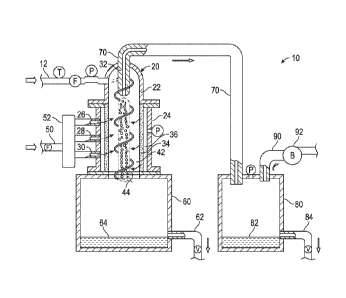
challenges and concerns.
[0004] In the area
of petroleum exploration and production from terrestrial
sources, pressurized fracturing fluids are sometimes used. The
pressurized
fracturing fluids are injected into putative or operational oil wells,
creating cracks in
geological formations at or near sources of petroleum products. The cracks
allow oil
and gas to escape from beneath the surface of the earth. The oil and gas are
collected with particularized apparatuses at the surface. The fracturing
fluids are
also released in the process. The hydraulic fracturing fluids are emitted from
the
earth as a mixture of water, various chemicals, hydrocarbons, natural
occurring
substances, and proppants. A goal in industry is to sufficiently cleanse water
from
used fracturing fluids for reuse in making fresh fracturing fluid for further
fracturing
operations. Another goal is to cleanse water found in used fracturing fluids
to a
degree where it is environmentally acceptable for disposal at an above-ground
location or facility. An ultimate goal is to cleanse water from used
fracturing fluid to a
point where it is in the form of potable water.
[0005] In addition
to fracturing fluids, water is often found in crude oil obtained
1
CA 2921868 2017-09-15
CA 02921868 2016-02-18
WO 2015/069686 PCT/US2014/063999
from an oil well. Separation of water from the crude oil is performed above
ground.
The separation technique used is typically a static gravity collection system
consisting of large holding tanks in combination with an oil ¨ water separator
system.
This process usually requires a long time for the oil and water mixture to
separate as
it resides in the large holding tanks. As a result, oil ¨ water separator
systems are
not particularly efficient or cost effective.
[0006] Water is also used to obtain crude oil, gas, and other petroleum
products from submarine locations. The water used in submarine, or off shore,
oil
production usually becomes contaminated with a variety of substances during
the
production process. Off shore oil wells produce a substantial amount of "sour
water"
in the course of pumping crude oil. The sour water is usually a mixture of
brackish
water, hydrogen sulfide, hydrogen sulfide ions, and various hydrocarbons. A
significant problem associated with using sour water is the sulfur content of
the sour
water. Sulfur in sour water is primarily found it two forms ¨ hydrogen sulfide
and
hydrogen sulfide ions. In addition to sulfur compounds in sour water,
hydrocarbons
and other petroleum products or compounds are problematic in sour water. If
sulfur
containing compositions, petroleum products, and volatile compounds could be
substantially removed from sour water, the sour water would be rendered
sufficiently
clean to be responsibly returned to the ocean or disposed of on land. In
addition,
water is often found in crude oil, gas, and other petroleum products obtained
in an off
shore production process. Separating water from these materials would enable
the
materials to be utilized rather than remaining of little or no use and in some
cases
hazardous.
[0007] One method of cleansing sour water or removing water from fracturing
fluids, petroleum, and petroleum products involves reacting or mixing a
gaseous
composition, such as air, carbon dioxide, or other appropriate gas with these
materials under certain conditions. In some circumstances, for example, an air
sparged hydrocyclone apparatus is used for the flotation or cleaning of coal,
for the
flotation or processing of tar sands, and for separating minerals from their
host
material by flotation. U.S. Patent Nos. 4,279,743; 4,397,741; and 4,399,027,
each
issued to Miller, disclose an air sparged hydrocyclone apparatus. While the
apparatuses of Miller and others may be able to separate solid materials from
water,
the solids are often recovered in relatively small amounts. In practice,
recovery of
2
CA 02921868 2016-02-18
WO 2015/069686 PCT/US2014/063999
small amounts of solid materials with these apparatuses and methods is usually
below the requirements of industry. Furthermore, Miller does not disclose an
apparatus or method capable of separating hydrocarbons, volatile organic
compounds, or sulfur ¨ containing compounds from water.
[0008] Shumeng, et al. disclose an air sparged hydrocyclone unit in published
Chinese patent application No. 200620148747.2 (Patent ID: CN 200981025 Y).
According to Shumeng, et al., the hydrocyclone unit is used for separating oil
from
water. In contrast with the present invention, the apparatus of Shumeng, et
al. does
not utilize negative pressure in conjunction with the apparatus. Nor does the
hydrocyclone unit of Shumeng et al. have unrestricted outflow through a lower
opening in the apparatus. Rather, a tapered outlet restricts outflow from the
unit.
[0009] Kalnins discloses a hydrocyclone unit in Published PCT application No.
WO 88/09696. The hydrocyclone unit utilizes a pressure-reducing device in the
form of a venturi positioned at the end of a fluid inlet where inflowing
contaminated
liquid is introduced to the lower end of the hydrocyclone unit. The negative
pressure created by the venturi increases the rate of flow of the inflowing
contaminated liquid. Kalnins
does not use negative pressure to separate
hydrocarbons, volatile organic compounds, or sulfur ¨ containing compositions
from
liquids, such as water. Nor does the hydrocyclone unit of Kalnins provide
unrestricted outflow of water and contaminants from the unit.
[0010] None of
these references discloses an apparatus or method capable of
eliminating or substantial reducing contaminants such as hydrocarbons,
volatile
organic compounds, sulfur, hydrogen sulfide, hydrogen sulfide ions, crude oil,
or
other petroleum products from water.
SUMMARY OF THE INVENTION
[0011] The present invention relates to an apparatus and method of removing
contaminants from water. In
particular, the present invention relates to a
specialized gas sparged hydrocyclone apparatus capable of cleansing or
purifying
liquid water contaminated with hydrocarbons, hydraulic fracturing fluids,
volatile
organic compounds, sulfur, hydrogen sulfide, hydrogen sulfide ions, crude oil,
or
other petroleum products. The invention also relates to a method of removing
hydrocarbons, hydraulic fracturing fluids, volatile organic compounds, sulfur,
3
CA 02921868 2016-02-18
WO 2015/069686 PCT/US2014/063999
hydrogen sulfide, hydrogen sulfide ions, crude oil, or other petroleum
products from
water, often in substantial amounts. Water cleansed or purified of these and
other
substances can often be reused in a particular process or used for a different
purpose.
[0012] The specialized gas sparged apparatus of the present invention
comprises a hydrocyclone top, or head portion, secured to a rigid container
located
below the hydrocyclone top. The hydrocyclone top has an inlet for accepting
and
directing contaminated liquid water into the hydrocyclone top. The
hydrocyclone
top has two outlets, referred to herein as an upper outlet and a lower outlet.
The
lower outlet directs the contaminated liquid water from the hydrocyclone top
downwardly into a sparger located below the hydrocyclone top. The upper outlet
is
positioned above the hydrocyclone unit. The upper outlet accepts and directs
upwardly flowing contaminates and residual water out of the sparger and
hydrocyclone combination.
[0013] The sparger is a porous substantially cylindrical element positioned
and retained inside the rigid container. In preferred embodiments, the sparger
is
made of sintered stainless steel. The rigid container has one or more inlets
traversing one or more walls of the rigid container. The inlets are in fluid
communication with a plenum positioned between inner walls of the rigid
container
and outer surfaces of the sparger. In use, an appropriate stripping gas is fed
under
pressure through the one or more inlets to the plenum. Once in the plenum, the
stripping gas flows from the plenum through the pores of the sparger into a
substantially cylindrical hollow interior area of the sparger. The hollow
interior area
of the sparger is located substantially in the center of the sparger. The
hollow
interior area of the sparger has an unrestricted opening at opposite ends,
referred
to herein as an upper opening and a lower opening. The unrestricted lower
opening in a lower, or bottom, portion of the hollow interior area permits
cleansed or
purified water to directly flow out of the sparger into a first reservoir
positioned
beneath the rigid container. The upper unrestricted opening in the hollow
interior
area of the sparger is in fluid communication with a vortex finder, or upper
nozzle,
located in the upper outlet of the hydrocyclone top. In use, contaminants and
residual water exit the sparger through the unrestricted upper opening and
vortex
finder. One end of a conduit is attached to the vortex finder. An opposite end
of
4
CA 02921868 2016-02-18
WO 2015/069686 PCT/US2014/063999
the conduit is attached to a second reservoir. Contaminants and residual water
are
conveyed from the sparger through the conduit to the second reservoir. A
source of
negative pressure or partial vacuum is provided to the second reservoir. The
source of negative pressure or partial vacuum is in fluid communication with
the
hollow interior area of the sparger and the first reservoir. Regulated outlets
are
provided to the first reservoir and the second reservoir.
[0014] In the process, contaminated liquid water is fed from a conduit through
the inlet of the hydrocyclone top. The hydrocyclone top causes the incoming
contaminated liquid water to acquire a circular flow and temporarily circulate
within
the hydrocyclone top. The circulating contaminated liquid water moves
downwardly
through the lower outlet of the hydrocyclone top in a spiraling or swirling
fashion to
form a vortex in the hollow interior area of the sparger. When the stripping
gas
passes, or percolates, into the hollow interior area of the sparger in the
presence of
contaminated liquid water, the stripping gas forms numerous bubbles in the
contaminated water. The vortex aids in mixing the bubbles with the
contaminated
liquid water in the hollow interior area of the sparger. A froth or foam of
stripping
gas and contaminated liquid water is formed as a result of the mixing action.
The
contaminants are captured and separated from most or all of the contaminated
liquid water by the bubbles in the froth or foam. Under the influence of
negative
pressure or partial vacuum present in the apparatus, a portion of the froth or
foam
collapses and transforms into a stream of liquid water substantially free of
contaminants. Collapse of the froth or foam occurs above the bottom of the
sparger. The stream of liquid water, stripped or otherwise substantially
removed of
contaminants, continues to flow downwardly through the unrestricted lower
opening
in the lower portion of the sparger directly into the first reservoir, or
storage vessel,
located beneath the hydrocyclone apparatus. Also with the aid of negative
pressure or partial vacuum present in the apparatus, contaminate ¨ containing
froth
or foam flows upwardly in the hollow interior area of the sparger. The
upwardly
flowing contaminate ¨ containing froth or foam flows out of the hollow
interior area
of the sparger through the vortex finder in the upper outlet in the
hydrocyclone top
and into the conduit. The contaminate ¨ containing froth or foam moves through
the conduit into the separate second reservoir. Once in the second reservoir,
the
froth or foam completely disintegrates or collapses. The contaminate ¨
containing
CA 02921868 2016-02-18
WO 2015/069686 PCT/US2014/063999
liquid water component of the froth or foam drops to a bottom portion of the
second
reservoir. The liquid water and any dissolved contaminates residing in the
bottom
of the second reservoir flow out of the second reservoir through a regulated
opening or conduit in the bottom of the second reservoir for appropriate
handling.
Volatile compounds, hydrocarbons, inorganic compositions, or other
contaminants
are also present in the froth or foam. As the froth or foam disintegrates in
the
second reservoir, volatile compounds, hydrocarbons, inorganic compositions, or
other contaminants present in the froth or foam separate from the froth or
foam.
Many of these materials enter a gaseous phase. The volatile compounds,
hydrocarbons, inorganic compositions, or other contaminants reside in an upper
portion of the second reservoir separate from the liquid water present in the
bottom
portion of the second reservoir. Negative pressure or partial vacuum in the
second
reservoir can also remove volatilizable materials remaining in the liquid
water. The
volatile compounds, hydrocarbons, inorganic compositions, or other
contaminants
flow out of the upper portion of the second reservoir through an opening or
conduit
where they are recovered for appropriate disposal or use.
[0015] Accordingly, one embodiment of the present invention relates to a
liquid purification apparatus comprising a hydrocyclone top, a rigid container
disposed beneath said hydrocyclone top, a sparger in said rigid container, a
plenum
between said rigid container and said sparger, at least one gas inlet in said
rigid
container in fluid communication with said plenum, a first reservoir beneath
said
sparger, wherein said sparger has a hollow interior area with open end in
unrestricted fluid communication with said first reservoir, a second reservoir
in fluid
communication with said hollow interior area of said sparger, and a vacuum
pump
attached to said second reservoir.
[0016] Another embodiment of the present invention relates to a liquid
purification apparatus comprising a containment vessel having at least one
rigid
wall, at least one gas inlet attached to said at least one rigid wall of said
containment vessel, wherein said containment vessel has at least one hollow
area
therein, wherein said containment vessel has a first end and a second end, a
rigid
substantially cylindrical microporous tube with a hollow interior and an
opening at
each end, wherein said tube is positioned in said at least one hollow area of
said
containment vessel and hermetically sealed to said containment vessel at each
end
6
CA 02921868 2016-02-18
WO 2015/069686 PCT/US2014/063999
of said tube, a housing attached to said first end of said containment vessel,
wherein said housing has an interior space delimited by a substantially curved
inner
wall, wherein said interior space has a center, an aperture in said
substantially
curved inner wall and a fluid inlet attached to said housing at an angle
relative to a
center point in said housing and in fluid communication with said aperture, a
first
outlet attached to said housing in fluid communication with said interior
space, a
second outlet attached to said housing at a substantially perpendicular angle
and in
fluid communication with said interior space, wherein said second outlet has a
central axis substantially aligned with said center of said interior space,
wherein
said first outlet is positioned on said housing substantially opposite said
second
outlet, wherein said second outlet is in fluid communication with one opening
of said
tube, a first reservoir attached to said second end of said containment vessel
and in
fluid communication with an open end of said tube, a fluid conduit having two
ends,
wherein one end of said fluid conduit is attached to said first outlet and
hermetically
sealed thereto, wherein a second end of said fluid conduit is attached to an
inlet of
a second reservoir and hermetically sealed thereto, and wherein said second
reservoir is attached to an inlet of a venturi vacuum system.
[0017] Another embodiment of the present invention relates to a method of
stripping contaminants from sour water comprising the steps of providing a
hydrocyclone unit including a hydrocyclone top, a rigid container disposed
beneath
said hydrocyclone top, a sparger in the rigid container, a plenum between said
rigid
container and said sparger, a first reservoir beneath said sparger, wherein
said
sparger has an open end in unrestricted fluid communication with said first
reservoir,
providing a flow of sour water to said hydrocyclone top and into said sparger,
providing a flow of stripping gas to said sparger, mixing said stripping gas
with said
sour water in the sparger to provide a sour water - containing froth and
stripped
water, capturing said sour water - containing froth from said hydrocyclone
unit,
separating stripping gas from said sour water - containing froth, disposing
said
stripping gas, and capturing said water stripped of sour water contaminants
from
said sparger.
BRIEF DESCRIPTION OF THE DRAWINGS
[0018] The accompanying drawings are included to provide a further
7
CA 02921868 2016-02-18
WO 2015/069686 PCT/US2014/063999
understanding of the invention and are incorporated in and constitute a part
of this
specification, illustrate embodiments of the invention, and together with the
description serve to explain the principles of the invention.
[0019] Figure 1 illustrates a schematic block diagram, with elements in
partial
section, of an air sparged hydrocyclone system suitable for use in the present
invention.
[0020] Figure 2 illustrates a cross-sectional view of an air sparger
suitable for
use in the present invention.
[0021] Figure 3 illustrates a schematic diagram of present invention in
the
form of a system. The system includes an apparatus of the present invention,
associated equipment, and indications of a method of using the apparatus.
DETAILED DESCRIPTION OF THE INVENTION
[0022] Figure 1 is a schematic block diagram of apparatus 10, portions of
which are in partial section. Figure 1 also illustrates a method of removing
hydrocarbons, hydraulic fracturing fluids, volatile organic compounds, sulfur,
hydrogen sulfide, hydrogen sulfide ions, crude oil, or other petroleum
products with
the apparatus 10. Water contaminated with hydrocarbons, hydraulic fracturing
fluids,
volatile organic compounds, sulfur, hydrogen sulfide, hydrogen sulfide ions,
crude
oil, or other petroleum products flows in a feed conduit 12 to a specialized
gas
sparged hydrocyclone unit 20. The flow rate in the conduit 12 may vary from
about
fifteen (15) gallons per minute to about thirty (30) gallons per minute. A
flow of about
fifteen (15) gallons per minute (gpm) is preferred.
[0023] Appropriate sensors, such as temperature, pressure, and flow rate,
and
valves, indicated respectively by T, P, F, and V, are associated with the
various
elements of the apparatus 10. Other appropriate valves and related equipment,
not
shown, are also associated with the conduit 12. Sensors and other control
devices
may be added as desired.
[0024] The unit 20 includes a hydrocyclone top 22 disposed at the top of a
rigid container 24. The rigid container 24 can have many forms including, but
not
limited to, straight and/or curved tubes of various cross-sections, spheres,
cubes,
rectangular boxes, cylinders, ovoids, and combinations thereof. The rigid
container
can be made of a variety of materials including, but not limited to, metals,
ceramics,
8
CA 02921868 2016-02-18
WO 2015/069686 PCT/US2014/063999
polymers, composites, and combinations thereof. A preferred material for the
rigid
container 24 is steel. The conduit 12 is connected to the hydrocyclone top 22.
Within the rigid container 24 is a sparger 34. The rigid container 24 and the
sparger
34 are secured to a first reservoir, "underflow drum," or "residual
disengagement
vessel" 60 positioned beneath, or under, the rigid container 24 and sparger 34
combination.
[0025] As illustrated in Figure 1, the sparger 34 is located within the
rigid
container 24. The inner diameter of the rigid container 24 is greater than the
outer
diameter of the sparger 34. Between the sparger 34 and the rigid container 22
is a
plenum 36. Gas inflowing from a conduit 50 and manifold 52 flows into the
plenum
36 under pressure through at least one input conduit, runner, or inlet.
Preferably, a
plurality of input conduits, runners, or inlets is used. Three such input
conduits,
runners, or inlets 26, 28 and 30 are illustrated in Figure 1. Gas flow to the
rigid
container 24 from the manifold 52 may vary in accordance with the flow rate in
the
feed conduit 12 of water contaminated with hydrocarbons, hydraulic fracturing
fluids,
volatile organic compounds, sulfur, hydrogen sulfides, hydrogen sulfide ions,
crude
oils, or other petroleum products. The gas flow rate is measured in standard
cubic
feet per minute (scfm). Gas flow to the rigid container 24 from the manifold
52 may
vary from about five (5) scfm to about fifteen (15) scfm. The reacting or
stripping gas
in the conduit 50 may be air, oxygen, carbon dioxide, nitrogen, argon, helium,
or
other appropriate gas. The sparger 34 is porous to the flow of a desired
stripping
gas. The positive pressure in the plenum insures the inwardly flowing
stripping gas
moves through the pores in the sparger 34 relatively uniformly along the
length of the
sparger. Uniform movement of stripping gas through the sparger 34 evenly mixes
the stripping gas with a downward spiraling flow of water contaminated with
hydrocarbons, hydraulic fracturing fluids, volatile organic compounds, sulfur,
hydrogen sulfides, hydrogen sulfide ions, crude oils, or other petroleum
products. In
preferred embodiments, the sparger 34 is porous through the entire sintered
tube.
Initially, stripping gas from the conduit 50 flows through one or more inlets
of the rigid
container 24 into the plenum 36. The stripping gas is at a pressure sufficient
to
cause the stripping gas to flow through the pores of the sparger 34. As the
stripping
gas flows from the plenum 36 through the pores in the sparger 34, the gas
enters a
chamber 42 in an interior area of the sparger.
9
CA 02921868 2016-02-18
WO 2015/069686 PCT/US2014/063999
[0026] The hydrocyclone top 22 induces a swirling or spiraling motion in
the
downwardly flowing contaminated water to form a vortex. As the stripping gas
enters
the interior area of the sparger in the presence of contaminated water,
numerous gas
bubbles are formed. The gas bubbles mix with the hydrocarbons, hydraulic
fracturing fluids, volatile organic compounds, sulfurs, hydrogen sulfides,
hydrogen
sulfide ions, crude oils, or other petroleum products in the contaminated
water. As a
result, a froth or foam is formed in the interior area of the sparger 34. The
froth or
foam contains a mixture of liquid water and hydrocarbon, hydraulic fracturing
fluid,
volatile organic compound, sulfur, hydrogen sulfide, hydrogen sulfide ion,
crude oil,
or other petroleum product contaminants.
[0027] A vacuum pump or blower 92 in the conduit 90 causes a negative
pressure or partial vacuum to be generated in the second reservoir, overflow
vessel,
separator, surge vessel, or drum 80. The negative pressure or partial vacuum
extends into conduit 70 through the hydrocyclone head 22 and into the interior
of the
sparger 34. With the application of negative pressure or partial vacuum, the
hydrocarbon, hydraulic fracturing fluid, volatile organic compound, sulfur,
hydrogen
sulfide, hydrogen sulfide ion, crude oil, or other petroleum product ¨
containing
portion of the froth or foam flows upwardly in the sparger, out of the
hydrocyclone top
22, through a vortex finder or upper nozzle 32 in the hydrocyclone top 22, and
into a
conduit 70. The upwardly flowing frothy or foamy mixture of residual water and
contaminates flows through the conduit 70 to a second reservoir, overflow
vessel,
separator, surge vessel, or drum 80. As the hydrocarbon, hydraulic fracturing
fluid,
volatile organic compound, sulfur, hydrogen sulfide, hydrogen sulfide ion,
crude oil,
or other petroleum product ¨ containing froth or foam enters the second
reservoir,
the froth or foam collapses or otherwise disintegrates under the influence of
negative
pressure or partial vacuum present in the second reservoir.
[0028] As the froth or foam collapses or disintegrates in the second
reservoir,
residual liquid water and any dissolved, suspended, admixed, or emulsified
materials
separate from the foam or froth and drop to a bottom portion of the second
reservoir,
overflow vessel, separator, surge vessel, or drum 80. The residual water and
any
dissolved, suspended, admixed, or emulsified materials flows outwardly from
the
bottom portion of the second reservoir, overflow vessel, separator, surge
vessel, or
drum 80 through a regulated conduit 84 for appropriate disposition. Large
arrows by
CA 02921868 2016-02-18
WO 2015/069686 PCT/US2014/063999
the respective conduits in Figure 1 show the direction of flow of the various
materials.
[0029] As residual liquid water and any dissolved, suspended, admixed, or
emulsified materials separate from the disintegrating or collapsing froth or
foam, the
hydrocarbon, hydraulic fracturing fluid, volatile organic compound, sulfur,
hydrogen
sulfide, hydrogen sulfide ion, crude oil, or other petroleum product
contaminants also
separate from the froth or foam. The hydrocarbon, hydraulic fracturing fluid,
volatile
organic compound, sulfur, hydrogen sulfide, hydrogen sulfide ion, crude oil,
or other
petroleum product contaminants occupy an upper portion of the second reservoir
apart from the liquid water residing in the bottom of the second reservoir.
The
hydrocarbons, hydraulic fracturing fluids, volatile organic compounds, sulfur,
hydrogen sulfides, hydrogen sulfide ions, crude oils, or other petroleum
products exit
the upper portion of the second reservoir through an opening or conduit 90
where
these and other volatile and/or gaseous materials are recovered for
appropriate
disposal or use.
[0030] The negative pressure or partial vacuum in the second reservoir,
overflow vessel, separator, surge vessel, or drum 80 also helps to disengage
any
remaining volatizable products from liquid water residing in the bottom
portion of the
second reservoir, overflow vessel, separator, surge vessel, or drum 80.
[0031] The downwardly flowing water, minus the contaminating hydrocarbons,
hydraulic fracturing fluids, volatile organic compounds, sulfur, hydrogen
sulfides,
hydrogen sulfide ions, crude oils, or other petroleum products which have been
captured in the upwardly flowing froth or foam within the sparger 34, freely
flows into
a first reservoir, "underflow drum," or "residual disengagement vessel" 60
through an
unrestricted opening in the bottom, or lower, end 44 of the sparger 34. Liquid
water
free of hydrocarbons, hydraulic fracturing fluids, volatile organic compounds,
sulfur,
hydrogen sulfides, hydrogen sulfide ions, crude oils, or other petroleum
products
flows out of the first reservoir, "underflow drum," or "residual disengagement
vessel"
60 through a conduit 62 and returns to a storage tank (not shown). An
appropriate
level of cleansed or purified liquid water is maintained in the first
reservoir,
"underflow drum," or "residual disengagement vessel" 60 by controlling outflow
of the
cleansed or purified liquid water into the conduit 62. The liquid water level
in the first
reservoir, underflow drum, or residual disengagement vessel 60 is indicated by
11
CA 02921868 2016-02-18
WO 2015/069686 PCT/US2014/063999
reference numeral 64.
[0032] The flow of the froth or foam from the chamber within the sparger 34
is
dynamically moved due to the differential pressure between the first
reservoir,
"underflow drum," or "residual disengagement vessel" 60 and the second
reservoir,
overflow vessel, separator, surge vessel, or drum 80.
[0033] The apparatus 10, including the hydrocyclone unit 20, with its
hydrocyclone top 22, the rigid container 24, and the upper nozzle or vortex
finder 32,
the first reservoir, "underflow drum," or "residual disengagement vessel" 60,
second
reservoir, overflow vessel, separator, surge vessel, or drum 80, and the
various
conduits comprise a sealed system. The negative pressure or partial vacuum in
the
system from the blower 92 is about six (6) inches of mercury (Hg).
[0034] The generally spiraling downward liquid flow in the sparger 34 is
schematically illustrated in Figure 1 by arrows and the generally upwardly
flow of the
foam or froth is also schematically illustrated in Figure 1 by arrows.
Similarly, the
flow of the stripping gas through the pores in the sparger is schematically
illustrated
in Figure 1 by small arrows. Figure 3 illustrates the present invention in
schematic
form. The schematic illustration shows a source of contaminated water (e.g.,
sour
water), a conduit transporting contaminated water to the gas reactor, a source
of
stripping gas and accompanying manifold and gas inlets, a first reservoir
(residual
disengagement vessel), an outlet from the first reservoir, a conduit
connecting the
gas reactor to a second reservoir (separator or surge drum), a conduit
connected to
a blower (i.e., a source of negative pressure or partial vacuum), and an
outflow
conduit for the second reservoir. Various meters or gauges and valves or
regulators
are also illustrated. Arrows in Figure 3 show the direction of flow of
contaminated
water, stripping gas, froth or foam, and reaction products in the system.
[0035] Figure 2 is an enlarged view in partial section through the sparger
34 of
Figure 1. For the following discussion, reference will primarily be made to
Figure 2,
but reference will also be made to Figure 1.
[0036] The sparger 34 comprises a tube or pipe made of one or more porous
materials. Suitable materials for the sparger 34 include, but are not limited
to,
sintered metallic particles, porous high density polyethylene, porous foil
mesh,
porous ceramic membrane made from aluminum oxide and/or silicon carbonate
membrane. Preferred sintered metallic particles are stainless steel. The pores
in
12
CA 02921868 2016-02-18
WO 2015/069686 PCT/US2014/063999
the sintered tube are of such a size as to permit the flow of a gas through
the tube or
pipe and into the interior of the sparger element, but not permit liquids to
pass
therethrough when gas is flowing through the sparger. Pores in the sintered
tube
range in size from about five microns (5pm) to about eighty microns (80 pm).
In
some embodiments, the pore size ranges from 15 about microns (15 pm) to about
45
microns (45 pm). In some embodiments, the pore size in the sintered tube
ranges
from about fifteen microns (15 pm) to about twenty-five microns (25 pm). In
other
embodiments, the pore size of the sintered tube ranges from about twenty-five
microns (25 pm) to about forty microns (40 pm). In other embodiments, the pore
size of the sintered tube ranges from about thirty microns (30 pm) to about
forty-five
microns (45 pm). In yet other embodiments, the pore size of the sintered tube
ranges from about thirty-five microns (35 pm) to about forty microns (40 pm).
[0037] Referring to Figure 2, the sparger 34 also includes a pair of
plates, a
top plate 38 and a bottom plate 40. The plates 38 and 40 are outwardly
extending
flanges which provide the elements for sealing and securing the sparger to the
hydrocyclone head 22, the rigid container 24, and the first reservoir,
"underflow
drum," or "residual disengagement vessel" 60.
[0038] Appropriate securing and sealing elements, such as bolts, o-rings,
welds, and the like have been omitted from the drawing figures. It is
understood the
various elements, including the various conduits and sensors, are
appropriately
secured and sealed in the apparatus and system.
[0039] The sparger element has been described in conjunction with the
stripping of contaminating products from water, it will be understood that
such
sparger may also be used in other applications. Another application is for the
removal of contaminates from water such as volatile organic compounds or
petroleum products.
[0040] It will be apparent to those skilled in the art that various
modifications
and variations can be made in the present invention without departing from the
spirit
or scope of the invention. Thus, it is intended that the present invention
cover the
modifications and variations of this invention provided they come within the
scope of
the appended claims and their equivalents.
13
CA 02921868 2016-02-18
WO 2015/069686 PCT/US2014/063999
EXAMPLES
[0041] Example 1
[0042] This example describes an embodiment of the present invention. In
this embodiment, a first component of a water purification apparatus, also
referred to
herein as a gas reactor, was constructed and attached to an upper portion of a
first
reservoir, "underflow drum," or "residual disengagement vessel". A second
reservoir,
"overflow vessel," separator, "surge vessel," or drum, was attached in fluid
communication to an outlet of the first component. An outlet from the second
reservoir was attached in fluid communication to an inlet of a venturi vacuum
system.
Optionally, a pressure reducing device such as a vacuum pump was attached to
the
second reservoir, overflow vessel, separator, surge vessel, or drum.
[0043] The first component, referred to as a containment vessel, rigid
container, or gas reactor had a main body made of two substantially identical
parts.
Each containment vessel part was constructed from a Standard Schedule 40, 316
S.S. pipe with an outer diameter of 10.16 cm (4.0 inch) and an inner diameter
of 9.02
cm (3.55 inch). The containment vessel part was cut to a length of 35.6 cm (14
inches). A machined stainless steel flat face plate, 15.24 cm (6.0 inch) in
diameter
and 1.27 cm (0.5 inch) thick, was welded to each end of each containment
vessel
part. Each flange had a 6.35 cm (2.5 inch) diameter hole through the center of
the
flange. Arrayed around each centrally located 6.35 cm (2.5 inch) diameter hole
were
four substantially equally spaced bolt holes drilled at a substantially ninety-
degree
(90 ) angle with respect to the flat surface of each flange. Each bolt hole
was sized
to accept a 0.95 cm (0.38 inch) by 3.81cnn (1.5 inch) stainless steel hex-head
bolt.
[0044] A rigid substantially cylindrical microporous tube with a hollow
interior
and an opening at each end was machined for each containment vessel. Each
microporous tube, also referred to herein as a sintered gas generator or gas
sparger,
was 5.1 cm (2 inches) in outer diameter and 34.3 cm (13.5 inches) in length.
The
wall of each microporous tube was 0.31 cm (0.125 inch) in thickness. Each
microporous tube was made of sintered stainless steel particles. Gas permeable
pores delimited by the sintered stainless steel particles traversed the wall
of each
microporous tube and had average diameters in a range from about twenty ¨ five
microns (25 pm) to about forty microns (40 pm).
14
CA 02921868 2016-02-18
WO 2015/069686 PCT/US2014/063999
[0045] A stainless steel support fitting in the form of a ring having a
6.67 cm
(2.63 inch) outer diameter, a 4.45 cm (1.75 inch) inner diameter, and a 1.27
cm (0.5
inch) thickness was welded to each end of each microporous tube. A microporous
tube with welded support fittings was placed inside each containment vessel
through
one of the 6.35 cm (2.5 inch) centrally located holes in the welded flanges of
the
vessel. Once a supported microporous tube was placed inside a containment
vessel, the support fittings were positioned inside the centrally located
holes in the
respective flanges. Distal surfaces of each support fitting were on the same
plane,
or flush, with exterior surfaces of each flange. A small space existed between
each
support fitting and the wall of each centrally located hole in each flange. An
appropriately sized rubber "0" ring was inserted into the space between each
support fitting and flange hole. Each microporous tube was thereby contained
within
and hermetically sealed to each containment vessel.
[0046] The first containment vessel was attached to the second containment
vessel with a 0.95 cm (0.38 inch) diameter by 3.81 cm (1.5 inch) stainless
steel hex-
head bolts placed through the bolt holes in the respective flanges at each end
of
each containment vessel. The entire length of the first containment vessel and
attached second containment vessel (i.e., gas reactor) was 71.1 cm (28
inches).
[0047] Each containment vessel had two (2) connection ports, or gas inlets,
1.9 cm (0.75 inches) in inner diameter (I.D.) welded to each side thereof. The
inlets
were in fluid communication with interior portions of each respective
containment
vessel and substantially equally spaced from each other. The inlets permitted
entry
of air or other gases into a space, or plenum, between inner walls of the
respective
containment vessels and outer surfaces of the respective microporous tubes
contained therein. A pressure gauge was attached to the containment vessel in
fluid
communication with the plenum area of the gas reactor. The pressure gauge was
rated at 0 ¨ 30 pounds per square inch gauge (psig). Once inside the
containment
vessels, air or other gases were free to enter and traverse pores of each
microporous tube. Air or other gases exiting the pores of each microporous
tube
entered an inner hollow area of each tube and were free to move through open
ends
of each tube.
[0048] The air or other gases introduced into the plenum of the gas reactor
were void of small particles, such as scale and/or dust. If such particles
were
CA 02921868 2016-02-18
WO 2015/069686 PCT/US2014/063999
present in the air or other gases, the particles could enter and obstruct the
pores of
the microporous tube. Accordingly, a filter having a ten micron (10 pm) pore
size
was placed inline of a hose, or conduit, supplying the air or other gases to
the gas
reactor. Pressure of the filtered air or other gases was controlled with a
pressure
regulator and fed downstream to a 0 ¨ 100 standard cubic feet per minute
(SCFM)
rotor meter. The filtered air or other gas moved at flow rate of twenty-five
(25) SCFM
and a pressure of ninety (90) psig.
[0049] The combined containment vessels and contained microporous tubes,
constituted a single containment vessel (i.e., gas reactor). When in a
vertical
orientation, the containment vessel, or gas reactor, had a top end and a
bottom end.
[0050] One end (i.e., bottom end) of the containment vessel was attached
with
bolts to a first reservoir or residual disengagement vessel. In this
embodiment, the
first reservoir was a standard fifty-five (55) gallon steel drum with a
corrosion-
resistant coating material on interior surfaces of the drum. The drum had a
standard
lock ring top. The first reservoir had an opening in an upper surface thereof
in fluid
communication with the hollow interior and unrestricted open end of the
microporous
tube located at the bottom of the containment vessel. In operation, fluids of
a
particular density or composition were able to freely move from within the
microporous tube and easily enter the first reservoir below the containment
vessel in
an unrestricted flow. The first reservoir was supplied with a 5.1 cm (2 inch)
manually
operated valve located near the bottom of the reservoir. The valve served to
permit
liquid retained in the first reservoir to exit the reservoir. The first
reservoir was
structurally modified to support the weight of the containment vessel,
microporous
tube, cyclone, and related components.
[0051] A Model U2 Krebs Cyclone FLS (The Krebs, Inc., Tucson, Arizona)
was attached to the opposite end (i.e., top end) of the containment vessel in
fluid
communication with the hollow interior portion of the microporous tube
contained
therein. The cyclone had one substantially cylindrical-shaped inlet attached
to one
side (i.e., side inlet) of the cyclone at an angle with respect to a center
point in the
cyclone. The cyclone also had two cylindrical outlets aligned substantially
perpendicular to the inlet and positioned substantially opposite one another
on the
cyclone housing. The outlets are referred to herein as an upper outlet and a
lower
outlet. The cyclone had an internal tube referred to herein as a vortex finder
placed
16
CA 02921868 2016-02-18
WO 2015/069686 PCT/US2014/063999
in the upper outlet of the cyclone.
[0052] The side inlet had a 3.8 cm (1.5 inch) outer diameter and was
attached
to a fitting with a 3.2 cm (1.25 inch) mechanical fitting to join pipes,
valves and
couplings to plastic, carbon steel/stainless steel and different type
fittings. The side
inlet served as an entry, or feed, nozzle for introducing contaminated
liquids, such as
sour water, in need of purification into the cyclone component of the present
invention. A feed line attached to the side inlet was used to introduce sour
water into
the apparatus through the entry nozzle. A manually operated liquid flow meter
was
installed in the feed line to enable the flow rate of the sour water to be
varied as
needed. In this example, a pressure of seventy (70) pounds per square inch
gauge
(psig) and a flow rate of fifty ¨ seven to one hundred fourteen (57 ¨ 114)
liters per
minute (LPM) or fifteen to thirty (15 ¨ 30) gallons per minute (GPM) was used.
An
inline globe valve and pressure gauge was installed downstream of the flow
meter.
[0053] The lower cyclone outlet had a 5.1 cm (2 inch) inner diameter and
was
placed directly over the 5.1cm (2 inch) hole in the flange and in fluid
communication
with one end (i.e., upper end) of the microporous tube. The cyclone was
mounted to
the welded flange at one end (e.g., top end) of the containment vessel with
four (4)
moveable clips. The cyclone was removable from the flange by loosening and
rotating the clips.
[0054] The upper outlet of the cyclone had an outer diameter of 3.8 cm (1.5
inch) and was connected directly to the vortex finder. The vortex finder was
connected to one end of a tubular fitting. The tubular fitting was bent at a
substantially right angle (i.e., 90 angle). The opposite end of the tubular
fitting was
to attach to a 3.2 cm (2.00 inch) diameter flexible reinforced fluid conduit
or hose.
When the present invention was in operation, the froth or foam containing
contaminants (i.e., dissolved gases, un-dissolved gases, hydrocarbons,
volatile
organic compounds, sulfur, inorganic compositions such as sulfur ¨ containing
compounds, crude oil, and other petroleum products) and residual water readily
moved upwardly from within the microporous tube through the vortex finder and
into
the flexible reinforced fluid conduit connected at an opposite end to a second
reservoir. The second reservoir was separate and distinct from the first
reservoir.
The opposite end of the flexible reinforced conduit was attached to the second
reservoir through a 5.1 cm (2 inch) outer diameter fitting attached to the top
of the
17
CA 02921868 2016-02-18
WO 2015/069686 PCT/US2014/063999
second reservoir. The flexible reinforced conduit was approximately 1.0 m (4.0
feet)
in length and maintained in a substantially straight, or linear, configuration
during
use. The substantially straight flexible reinforced conduit was positioned at
a slightly
sloping, or declining, angle from the cyclone top to the entry fitting of the
second
reservoir.
[0055] In this embodiment, the second reservoir was a standard fifty-five
(55)
gallon steel drum with a corrosion-resistant coating material on interior
surfaces of
the drum. The drum had a standard lock ring top. A venturi device referred to
as a
Tornado Air Powered Venturi BEM02893 (West Chicago, Illinois 60185) was
mounted in fluid communication with interior reservoir areas of the drum and
hermetically sealed to the top, or lid, of the drum. In use, the venturi
device reduced
gas pressure or otherwise created a partial vacuum in the second reservoir. In
operation, a partial vacuum or reduced pressure of 12.7 cm (5.0 inches) of
mercury
(Hg) was produced by the venturi device. The venturi device was driven by a
source
of air at a pressure of 60 pounds per square inch, gauge (psig).
Alternatively, a
vacuum pump was attached to the second reservoir in place of or in addition to
the
venturi device.
[0056] Once the froth or foam entered the second reservoir, the reduced
pressure or partial vacuum present therein caused the froth or foam to
disintegrate
or collapse and release various chemical compounds from the froth or foam. The
chemical compounds included, but were not limited to, petroleum oil, gaseous
compounds, hydrocarbons, sulfur, sulfur ¨ containing compounds, and volatile
organic compounds (VOC's). Disassociated concentrated vapors and volatile
compounds were discharged through an adaptor attached to the venturi or vacuum
unit. A 7.62 cm (3 inch) diameter hose was attached to the venturi vacuum unit
and
was used to transfer the disassociated concentrated vapors and volatile
compounds
to a container for appropriate treatment prior to disposal. Liquids in the
froth or foam
fell to the bottom of the second reservoir as the froth or foam disintegrated
or
collapsed and were collected through the aforementioned exit valve. Once
collected,
the liquid from the second reservoir was appropriately treated for disposal or
salvage.
[0057] It will be apparent to those skilled in the art that various
modifications
and variations can be made in the present invention without departing from the
spirit
18
CA 02921868 2016-02-18
WO 2015/069686 PCT/US2014/063999
or scope of the invention. Thus, it is intended that the present invention
cover the
modifications and variations of this invention provided they come within the
scope of
the appended claims and their equivalents.
19