Language selection

Search

Patent 2921967 Summary

Third-party information liability

Some of the information on this Web page has been provided by external sources. The Government of Canada is not responsible for the accuracy, reliability or currency of the information supplied by external sources. Users wishing to rely upon this information should consult directly with the source of the information. Content provided by external sources is not subject to official languages, privacy and accessibility requirements.

Claims and Abstract availability

Any discrepancies in the text and image of the Claims and Abstract are due to differing posting times. Text of the Claims and Abstract are posted:

  • At the time the application is open to public inspection;
  • At the time of issue of the patent (grant).
(12) Patent: (11) CA 2921967
(54) English Title: PROCESSING A NOISY ANALOGUE SIGNAL
(54) French Title: TRAITEMENT D'UN SIGNAL ANALOGUE BRUYANT
Status: Granted
Bibliographic Data
(51) International Patent Classification (IPC):
  • H04L 27/18 (2006.01)
(72) Inventors :
  • MAYO, RICHARD HAMMOND (United Kingdom)
(73) Owners :
  • HANWHA PHASOR LTD. (United Kingdom)
(71) Applicants :
  • PHASOR SOLUTIONS LIMITED (United Kingdom)
(74) Agent: NORTON ROSE FULBRIGHT CANADA LLP/S.E.N.C.R.L., S.R.L.
(74) Associate agent:
(45) Issued: 2020-08-25
(86) PCT Filing Date: 2013-08-23
(87) Open to Public Inspection: 2014-02-27
Examination requested: 2018-05-29
Availability of licence: N/A
(25) Language of filing: English

Patent Cooperation Treaty (PCT): Yes
(86) PCT Filing Number: PCT/GB2013/052235
(87) International Publication Number: WO2014/030016
(85) National Entry: 2016-02-22

(30) Application Priority Data:
Application No. Country/Territory Date
1215114.8 United Kingdom 2012-08-24

Abstracts

English Abstract

A device is provided for correlating at least one noisy analogue signal which is one of a plurality of signals obtained by a plurality of receivers. The device comprises a 1-bit quantisation element to which the noisy signal is supplied; a comparator configured to compare the quantised signal with a reference signal which is a consensus signal obtained by averaging data from the plurality of receivers; and an up/down counter that is configured to be incremented by a subset of the comparison signal.


French Abstract

L'invention concerne un dispositif conçu pour corréler au moins un signal analogique bruité faisant partie d'une pluralité de signaux obtenus par une pluralité de récepteurs. Le dispositif comporte un élément de quantification de 1 bit auquel est envoyé le signal bruité lors de l'utilisation; un comparateur configuré pour comparer le signal quantifié à un signal de référence qui est un signal consensus obtenu en calculant la moyenne des données de la pluralité de récepteurs; un compteur progressif/dégressif qui est configuré pour être incrémenté par un sous-ensemble du signal de comparaison.

Claims

Note: Claims are shown in the official language in which they were submitted.


CLAIMS
1. A method of correlating at least one noisy analogue signal, wherein the
noisy signal
is one of a plurality of signals obtained by a plurality of receivers; the
method comprising:
1-bit quantising the noisy signal by 1-bit quantising each of in-phase and
quadrature
components of the noisy signal;
comparing the quantised signal with a quantised reference signal by comparing
each
of the quantised in-phase and quadrature components of the noisy signal with
each of
quantised in-phase and quadrature components of the reference signal, wherein
the
reference signal is a consensus signal obtained by combining data from the
plurality of
receivers;
if the quantised in-phase components of the noisy signal and the reference
signal are
equal, incrementing or decrementing a first counter value in a first direction
and, if not,
incrementing or decrementing the counter value in a second direction;
if the quantised quadrature components of the noisy signal and the reference
signal
are equal, incrementing or decrementing the first counter value in the first
direction and, if
not, incrementing or decrementing the first counter value in the second
direction;
if the quantised in-phase component of the noisy signal and the quantised
quadrature
component of the reference signal are equal, incrementing or decrementing a
second
counter value in a first direction and, if not, incrementing or decrementing
the second
counter value in a second direction; and
if the quantised quadrature component of the noisy signal and the quantised in-
phase
component of the reference signal are equal, incrementing or decrementing the
second
counter value in the second direction and, if not, incrementing or
decrementing the second
counter value in the first direction.
2. The method according to claim 1 , comprising:
stopping incrementing or decrementing the first and second counter values when
one
of the first and second counter values reaches full scale.
3. The method according to claim 1 or 2, comprising:
determining the phase offset between the phase of the noisy signal and the
phase of
the reference signal by considering the first and second counter values;
altering the phase of the noisy signal in order to correct for the phase
offset; and
resetting the first and second counter values.

7

4. The method according to any one of claims 1 to 3, further comprising
inverting the
quantised signal if there is a strong negative correlation.
5. The method according to any one of claims 1 to 4, comprising excluding
the noisy
signal from the consensus signal if the noisy signal consistently sits beyond
a predetermined
range of the consensus signal.
6. The method according to any one of claims 1 to 5, wherein the reference
signal is
obtained by at least one of summing and averaging data from the plurality of
receivers.
7. A device for correlating at least one noisy analogue signal, wherein the
noisy signal
is one of a plurality of signals obtained by a plurality of receivers, the
device comprising:
a 1-bit quantisation element to which is supplied, in use, the noisy signal,
wherein the
1-bit quantisation element is configured to 1-bit quantise each of in-phase
and quadrature
components of the noisy signal;
a comparator configured to compare the quantised signal with a reference
signal to
generate a comparison signal, wherein the comparator is configured to compare
each of the
quantised in-phase and quadrature components of the noisy signal with each of
quantised
in-phase and quadrature components of the reference signal, the reference
signal is a
consensus signal obtained by combining data from the plurality of receivers;
and
first and second counters that are each configured to be incremented or
decremented by at least some of the comparison signal, wherein:
if the quantised in-phase components of the noisy signal and the reference
signal are equal, the first counter is configured to be incremented or
decremented in
a first direction and, if not, the first counter is configured to be
incremented or
decremented in a second direction;
if the quantised quadrature components of the noisy signal and the reference
signal are equal, the first counter is configured to be incremented or
decremented in
the first direction and, if not, the first counter is configured to be
incremented or
decremented in the second direction;
if the quantised in-phase component of the noisy signal and the quantised
quadrature component of the reference signal are equal, the second counter is
configured to be incremented or decremented in a first direction and, if not,
the
second counter is configured to be incremented or decremented in a second
direction; and
if the quantised quadrature component of the noisy signal and the quantised
in-phase component of the reference signal are equal, the second counter is
8

configured to be incremented or decremented in the second direction and, if
not, the
second counter is configured to be incremented or decremented in the first
direction.
8. The device according to claim 7, further comprising a sampling device
configured to
sample the comparison signal, and wherein the each counter is configured to be

incremented each time the sampling device samples the comparison signal.
9. The device according to claim 7 or 8, further comprising an oscillator
configured to
modify the phase of the quantised signal.
10. The device according to any one of claims 7 to 9, wherein the
comparator is an XOR
gate.
11. The device according to any one of claims 7 to 10, wherein:
the first and second counters are configured to be stopped when one of the
first and
second counters reaches full scale.
12. The device according to any one of claims 7 to 11, wherein:
the device is configured to determine the phase offset between the phase of
the
noisy signal and the phase of the reference signal from the values of the
first and second
counters and
the device comprises a control block configured to control an oscillator which
alters
the phase of the noisy signal in order to correct for the phase offset.
13. The device according to any one of claims 7 to 11, further comprising a
control block
configured to reset each of the first and second counters.
14. The device according to any one of claims 7 to 13, further comprising
an inverting
element configured to invert the quantised signal if there is a strong
negative correlation.
15. The device according to any one of claims 7 to 14, further comprising a
control circuit
configured to exclude the noisy signal from the consensus signal if the noisy
signal
consistently sits beyond a predetermined range of the consensus signal.
16. The device according to any one of claims 7 to 15, the reference signal is
obtained by at
least one of summing and averaging data from the plurality of receivers.
9


17. An apparatus comprising a plurality of receivers, each of the plurality
of receivers
comprising the device according to any one of claims 7 to 16.
18. A method of correlating at least one noisy analogue signal, wherein the
noisy signal
is one of a plurality of signals obtained by a plurality of receivers, the
method comprising:
1-bit quantising the noisy signal by 1-bit quantising each of in-phase and
quadrature
components of the noisy signal;
1-bit quantising a reference signal, wherein the reference signal is a
consensus
signal obtained by combining data from the plurality of receivers,
comparing the quantised noisy signal with the quantised reference signal by
comparing each of the quantised in-phase and quadrature components of the
noisy signal
with each of quantised in-phase and quadrature components of the reference
signal,
performing at least one of the following steps (a) and (b);
(a) incrementing or decrementing a first counter value as follows:
if the quantised in-phase components of the noisy signal and the reference
signal are equal, incrementing or decrementing the first counter value in a
first
direction and, if not, incrementing or decrementing the first counter value in
a second
direction, and
if the quantised quadrature components of the noisy signal and the reference
signal are equal, incrementing or decrementing the first counter value in the
first
direction and, if not, incrementing or decrementing the first counter value in
the
second direction;
(b) incrementing or decrementing a second counter value as follows:
if the quantised in-phase component of the noisy signal and the quantised
quadrature component of the reference signal are equal, incrementing or
decrementing the second counter value in a first direction and, if not,
incrementing or
decrementing the second counter value in a second direction; and
if the quantised quadrature component of the noisy signal and the quantised
in-phase component of the reference signal are equal, incrementing or
decrementing
the second counter value in the second direction and, if not, incrementing or
decrementing the second counter value in the first direction.
19. The method according to claim 18, further comprising inverting the
quantised noisy
signal if there is a strong negative correlation.


20. The method according to claim 18, further comprising excluding the
noisy signal from
the consensus signal if the noisy signal consistently sits beyond a
predetermined range of
the consensus signal.
21. The method according to claim 18, wherein the reference signal is
obtained by at
least one of summing and averaging data from the plurality of receivers.
11

Description

Note: Descriptions are shown in the official language in which they were submitted.


CA 02921967 2016-02-22
WO 2014/030016
PCT/GB2013/052235
PROCESSING A NOISY ANALOGUE SIGNAL
Field
The present invention relates to a method of, and a device for, correlating at
least one noisy
analogue signal which is one of a plurality of signals obtained by a plurality
of receivers.
Background
The correlation of one or more noisy analogue signals may be effective even
when the
signal is polluted by noise that is of greater amplitude than the signal. One
known approach
is to correlate the noisy analogue signal with another signal, such as a
reference signal of
known characteristics. This is achieved by multiplying together the two
signals and then
integrating the result. When the integral is near-zero, the signals are not
correlated. When
the integral is strongly positive, the signals are correlated and when the
integral is strongly
negative, the signals are correlated, but one is inverted in relation to the
other.
However, analogue integrators are prone to drift. Furthermore, the
multiplication and
integration of the two signals is quite resource intensive.
The present invention has been devised in part to address these issues.
Summary
According to a first aspect of the present invention there is provided a
method of correlating
at least one noisy analogue signal, wherein the noisy signal is one of a
plurality of signals
obtained by a plurality of receivers; the method comprising the steps of:
1-bit quantising the noisy signal;
comparing the quantised signal with a quantised reference signal, wherein the
reference signal is a consensus signal obtained by averaging data from the
plurality of
receivers; and
sampling the comparison signal (in other words a signal resulting from the
comparing
step) to increment an up/down counter.
When working with a very noisy signal, digitising the signal using 1-bit
quantisation extracts
the majority of the available information from the noisy signal. The presence
of a lot of noise
means that the provision of additional resolution in the digital signal would
not add any
further information.
1

CA 02921967 2016-02-22
WO 2014/030016
PCT/GB2013/052235
The step of sampling the comparison signal to increment an up/down counter,
effectively
performs the integration required to identify the correlation, or lack
thereof, between the
signals. The use of an up/down counter, in place of the integrator required in
the analogue
approach known in the art, provides a much less computationally intensive
operation, by
merely adding rather than performing an integration.
The presence of a large amount of random noise affects the value of the count
proportional
to the signal-to-noise ratio of the noisy signal. The strength of the required
signal can be
measured and optimised even when the noise is much stronger.
Noise contributed by each receiver is generally independently from noise
contributed by the
other receivers. Thus, correlating the signals in this way can reduce the
noise associated
with the reference or consensus signal.
Each of the plurality of signals may originate from a single source. The
signal from the
source may be an n-state phase-shift keyed signal.
The method may comprise: identifying, i.e. determining, the phase offset
between the phase
of the noisy signal and the phase of the reference signal by considering the
value of the
up/down counter; and altering the phase of the noisy signal to correct for the
phase offset.
The method may comprise: 1-bit quantising each of in-phase and quadrature
components of
the noisy signal; comparing each of the quantised in-phase and quadrature
components of
the noisy signal with each of quantised in-phase and quadrature components of
the
reference signal; if the quantised in-phase components of the noisy signal and
the reference
signal are equal, incrementing or decrementing a first up/down counter in a
first direction
(e.g. up) and, if not, incrementing or decrementing the first up/down counter
in a second
direction (e.g. down); if the quantised quadrature components of the noisy
signal and the
reference signal are equal, incrementing or decrementing the first up/down
counter in the
first direction and, if not, incrementing or decrementing the first up/down
counter in the
second direction; if the quantised in-phase component of the noisy signal and
the quantised
quadrature component of the reference signal are equal, incrementing or
decrementing a
second up/down counter in a first direction and, if not, incrementing or
decrementing the
second up/down counter in a second direction; and if the quantised quadrature
component
of the noisy signal and the quantised in-phase component of the reference
signal are equal,
incrementing or decrementing the second up/down counter in the second
direction and, if
not, incrementing or decrementing the second up/down counter in the first
direction.
2

CA 02921967 2016-02-22
WO 2014/030016
PCT/GB2013/052235
The method may comprise stopping the first and second up/down counters when
one of the
first and second up/down counters reaches full scale.
The method may comprise: determining the phase offset between the phase of the
noisy
signal and the phase of the reference signal by considering the values of the
first and
second up/down counters; altering the phase of the noisy signal in order to
correct for the
phase offset; and resetting the first and second up/down counters.
The method may comprise inverting the quantised signal if there is a strong
negative
correlation.
The method may comprise excluding the noisy signal from the consensus signal
if the noisy
signal consistently sits beyond a predetermined range of the consensus signal.
According to a second aspect of the present invention there is provided a
device for
correlating at least one noisy analogue signal, wherein the noisy signal is
one of a plurality of
signals obtained by a plurality of receivers, the device comprising:
a 1-bit quantisation element to which is supplied, in use, the noisy signal;
a comparator configured to compare the quantised signal with a reference
signal,
wherein the reference signal is a consensus signal obtained by averaging data
from the
plurality of receivers; and
an up/down counter that is configured to be incremented by a subset of the
comparison signal (in other words a signal provided by the comparator).
The device may comprise a sampling device configured to sample the comparison
signal,
and the up/down counter may be configured to be incremented each time, or just
after each
time, the sampling device samples the comparison signal.
The comparator may be an XOR logic operator.
The device may be configured to alter the phase of the noisy analogue signal.
The phase
alteration of the noisy signal is performed in order to optimise the
correlation.
The device may further comprise a control block configured to reset the or
each up/down
counter.
3

CA 02921967 2016-02-22
WO 2014/030016
PCT/GB2013/052235
There may be provided apparatus comprising the plurality of receivers, each of
the plurality
of receivers comprising the device.
Further optional features of the present invention are specified in the
dependent claims.
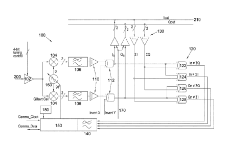
Brief Description of the Drawings
Certain embodiments of the present invention are described below, by way of
example only,
with reference to the accompanying Figure 1 which illustrates a device for
correlating at least
one noisy analogue signal.
Detailed Description of the Certain Embodiments
Figure 1 shows a device 100, or phase controlled receiver, for correlating at
least one noisy
analogue signal 200, being a Phased Shift Keyed signal. The noisy analogue
signal 200 is
obtained from one of a plurality of receivers. The signal from each of the
receivers is
combined to provide a consensus signal 210. The consensus signal 210 has
components
!OUT and QOuT that is the summation of the in-phase and quadrature components
of the
analogue signals received from each of the receivers.
The noisy analogue signal 200 is provided modulated onto a microwave frequency
carrier. It
is introduced to low noise amplifier 102 then to multipliers 104 which brings
the signal back
to baseband. The signal is then filtered at filter 106 which removes signals
outside the
baseband frequency band.
Once the noisy signal 200 has been prepared, it can then be digitised in the 1-
bit
quantisation elements 110. Similar 1-bit quantisation elements 130 are
provided to digitise
the consensus signal 210. The elements 110, 130 identify whether or not the
signal exceeds
a predetermined level and allocate a binary value as appropriate. The noisy
signal 200 is
then provided to an XOR gate which has its other input controlled in order to
either maintain
or invert the signal. The provision of the XOR gates enables a strongly
negative correlation
to be inverted to provide a strongly positive correlation or vice versa.
A comparator 120 is provided to compare the prepared, and potentially
inverted, noisy signal
200 (In, Qn) with the consensus signal 210 (ZI, ZQ). The comparator 120
comprises four
XOR gates 122, 124, 126 and 128. XOR gates 124 and 126 give correlation of the
amplitude of the signal. Whilst XOR gates 122 and 128 give correlation of the
phase of the
signal.
4

CA 02921967 2016-02-22
WO 2014/030016
PCT/GB2013/052235
The outputs of the four XOR gates control the UP/DOWN status of a counter
block140 which
is clocked at intervals as frequent as is justified by the frequency bandwidth
of the signal
being received. There is a counter that gives the amplitude of correlation and
a counter that
gives the phase error. The counter that gives the amplitude of correlation is
incremented or
decremented according to:
If In = Zl count up
If Qn = ZQ count up
If In # Zl count down
If Qn ZQ count down
The counter that gives the phase error is incremented or decremented according
to:
If In = ZQ count up
If In # ZQ count down
If Qn = Zl count down
If Qn Zl count up
When one of the counters reaches full scale, either positive or negative,
counting is stopped
on the counters. By considering the value of the counters, the phase offset
can be identified
and the control block 150 is configured to control an oscillator 160 which
alters the phase of
the signal in the multipliers 104 in order to correct the phase. A signal from
the control block
150 resets the counters, i.e. to their mid range zero position. Another
reading may be then
commenced. Accordingly, the phase offset is driven to zero.
The phase offset is equal to an angle defined by the values of the counters.
In particular, if
the value (hereinafter referred to as the "phase counter value") of the
counter that gives the
phase error is plotted on the x-axis and the value of the counter that gives
the amplitude of
correlation (hereinafter referred to as the "amplitude counter value") is
plotted on the y-axis,
then the phase error is defined as the angle between the (vertical) line which
is the positive
part of the y-axis and the line from the origin to the point whose x- and y-
coordinates are
defined by the phase counter value and amplitude counter value respectively.
The angle is
defined such that is can vary between ¨180 degrees (minus 180 degrees) and
+180 degrees
(plus 180 degrees). The angle is negative if the phase counter value is
negative and vice
versa. Accordingly, the angle is given by the arctangent of the ratio of the
phase counter
value to the (full-scale) amplitude counter value for angles between ¨45
degrees and +45
5

CA 02921967 2016-02-22
WO 2014/030016
PCT/GB2013/052235
degrees, by 90 degrees minus the arctangent of the ratio of the amplitude
counter value to
the (full-scale) phase counter value for angles between +45 degrees and +135
degrees, etc.
It is not necessary to determine the phase offset when one of the counters has
reached full
scale. The phase offset can be determined from any pair of phase and amplitude
counter
values.
In order to preserve the integrity of the consensus signal 210, one or more of
the receivers,
or parts thereof, may have to be disregarded. This is achieved using a control
circuit 170.
Signals from receivers can only be included in the consensus signal if they
are within a
predetermined percentage of the consensus signal. If the noisy signal 200
consistently sits
beyond the predetermined range, despite inverting the signal with the XOR
gates 112 and
changing the phase by up to 90 using the oscillator 160 then the control
circuit 170 can
exclude it from the consensus signal. This enhances the integrity of the
consensus signal.
The control block 150 is also provided with a power on reset facility 180
which ensures that
the up/down counters are all reset to their midrange zero point when the
device 100 is
initialised.
It will be appreciated that many other modifications may be made to the
embodiments
hereinbefore described.
6

Representative Drawing
A single figure which represents the drawing illustrating the invention.
Administrative Status

For a clearer understanding of the status of the application/patent presented on this page, the site Disclaimer , as well as the definitions for Patent , Administrative Status , Maintenance Fee  and Payment History  should be consulted.

Administrative Status

Title Date
Forecasted Issue Date 2020-08-25
(86) PCT Filing Date 2013-08-23
(87) PCT Publication Date 2014-02-27
(85) National Entry 2016-02-22
Examination Requested 2018-05-29
(45) Issued 2020-08-25

Abandonment History

There is no abandonment history.

Maintenance Fee

Last Payment of $263.14 was received on 2023-08-14


 Upcoming maintenance fee amounts

Description Date Amount
Next Payment if standard fee 2024-08-23 $347.00
Next Payment if small entity fee 2024-08-23 $125.00

Note : If the full payment has not been received on or before the date indicated, a further fee may be required which may be one of the following

  • the reinstatement fee;
  • the late payment fee; or
  • additional fee to reverse deemed expiry.

Patent fees are adjusted on the 1st of January every year. The amounts above are the current amounts if received by December 31 of the current year.
Please refer to the CIPO Patent Fees web page to see all current fee amounts.

Payment History

Fee Type Anniversary Year Due Date Amount Paid Paid Date
Reinstatement of rights $200.00 2016-02-22
Application Fee $400.00 2016-02-22
Maintenance Fee - Application - New Act 2 2015-08-24 $100.00 2016-02-22
Maintenance Fee - Application - New Act 3 2016-08-23 $100.00 2016-02-22
Maintenance Fee - Application - New Act 4 2017-08-23 $100.00 2017-08-10
Request for Examination $800.00 2018-05-29
Maintenance Fee - Application - New Act 5 2018-08-23 $200.00 2018-07-18
Maintenance Fee - Application - New Act 6 2019-08-23 $200.00 2019-07-19
Registration of a document - section 124 2020-06-23 $100.00 2020-06-23
Final Fee 2020-06-25 $300.00 2020-06-23
Maintenance Fee - Application - New Act 7 2020-08-24 $200.00 2020-08-11
Registration of a document - section 124 $100.00 2020-11-19
Maintenance Fee - Patent - New Act 8 2021-08-23 $204.00 2021-08-20
Maintenance Fee - Patent - New Act 9 2022-08-23 $203.59 2022-08-16
Maintenance Fee - Patent - New Act 10 2023-08-23 $263.14 2023-08-14
Owners on Record

Note: Records showing the ownership history in alphabetical order.

Current Owners on Record
HANWHA PHASOR LTD.
Past Owners on Record
HANWHA SYSTEMS EUROPE, LTD.
PHASOR SOLUTIONS LIMITED
Past Owners that do not appear in the "Owners on Record" listing will appear in other documentation within the application.
Documents

To view selected files, please enter reCAPTCHA code :


To view images, click a link in the Document Description column. To download the documents, select one or more checkboxes in the first column and then click the "Download Selected in PDF format (Zip Archive)" or the "Download Selected as Single PDF" button.

List of published and non-published patent-specific documents on the CPD .

If you have any difficulty accessing content, you can call the Client Service Centre at 1-866-997-1936 or send them an e-mail at CIPO Client Service Centre.


Document
Description 
Date
(yyyy-mm-dd) 
Number of pages   Size of Image (KB) 
Final Fee / Change to the Method of Correspondence 2020-06-23 5 152
Representative Drawing 2020-07-31 1 12
Cover Page 2020-07-31 1 41
Abstract 2016-02-22 1 64
Claims 2016-02-22 4 144
Drawings 2016-02-22 1 23
Description 2016-02-22 6 262
Representative Drawing 2016-03-08 1 12
Cover Page 2016-03-14 2 44
Request for Examination 2018-05-29 2 73
Examiner Requisition 2019-03-04 4 224
Amendment 2019-09-04 8 322
Claims 2019-09-04 5 197
International Search Report 2016-02-22 10 323
National Entry Request 2016-02-22 4 173