Note: Descriptions are shown in the official language in which they were submitted.
CA 02922027 2016-02-26
Switching Structure of Water Dispensing Apparatus
BACKGROUND OF THE PRESENT INVENTION
to FIELD OF INVENTION
[0002] The present invention relates to a water dispensing apparatus,
specifically to a
water dispensing apparatus with a switching structure, wherein a switching
valve is set
between water channels of the water dispensing apparatus and is actuated by a
manual
actuation member to enable to a manual operation of the manual actuation
member to
control the switch valve.
DESCRIPTION OF RELATED ARTS
[0003] Conventional water dispensing apparatuses are designed for allowing the
users
to easily operate the switch to turn on and off for water spraying and,
therefore, have
actuation members for manual pushing. These structures of water dispensing
apparatus
include the following. A main body has an outlet channel and an inlet channel.
The outlet
channel and the inlet channel connect the water flow with a through channel as
a bridging
CA 02922027 2016-02-26
channel. The through channel is pivotingly assembled with a pivot valve,
wherein the
pivot valve has a water sealing portion and the pivot valve is mounted through
the
through channel. The two ends of the pivot valve assemblingly connect with an
actuation
member to allow the radial angle of the pivoting of the pivot valve to be
driven by
operating the actuation member, which makes the water sealing portion to close
the outlet
opening or open the inlet channel.
[0004] The opening of the outlet channel belongs to a round bore type. Such
round
bore type of outlet opening is a common structure for several conventional
water
dispensing apparatuses. Because of such design of round bore type and the
water sealing
.. portion matching the outlet opening, the back of the water sealing portion
is bearing both
of the impact pressure of the flow entered from the inlet channel and the
suction force of
the water leaving the outlet opening. As a result, the water sealing portion
bears two
traction forces, which could cause the water sealing portion to be flushed out
of the outlet
opening or cause the water sealing portion to be distorted and fail to
completely close the
outlet channel, which causes leakage. Moreover, it requires a longer operation
stroke to
have the water sealing portion to close the outlet opening
[0005] Improvements of the present invention include to make the actuation
member to
bring the pivoting of the pivot valve for leading the water sealing portion to
close or open
the inlet opening, so as to achieve the objective of shortening the stroke of
the actuation
.. member, which allows the users to use a more efficient and easy way to turn
on or off the
water dispensing apparatus. Besides, another objective is that the periphery
of the water
sealing portion has a groove, wherein the groove sleevedly has a sealing
element. When
the sealing element is put in the groove, there still is a minor gap left to
guide water flow
to enter the groove and to flush back to expand the sealing element, which
make the
sealing element to attach to the inlet opening more closely, which achieve the
objective
of preventing leakage by having the sealing element close the inlet opening
more
securely.
2
CA 02922027 2016-02-26
SUMMARY OF THE PRESENT INVENTION
[0006] A switching structure of water dispensing apparatus has an inlet
channel and an
outlet channel in a main body of the water dispensing apparatus. The inlet
channel and
the outlet channel has a lateral channel therebetween. The lateral channel is
pivotingly
assembled with a pivot valve. The pivot valve is mounted through the lateral
channel.
Two ends of the pivot valve is operatively connect to an actuation member,
wherein the
actuation member is arranged to pivotally move the pivot valve so as to adjust
the radial
angle of the pivot valve and to therefore control the outlet opening and the
inlet opening
between an open state and a close state.
[0007] The feature is in that: the shape of the inlet opening has a bore type
with a
longitudinal width larger than a transverse width thereof, which shape
includes oblong
oval shape. The pivot valve has a water sealing portion and a water passing
portion. The
shape of the water sealing portion of the pivot valve matches with the bore
type of the
inlet opening. The water sealing portion surroundingly has a sealing element.
Two
.. scaling rings are coupled at the first and second lateral sides of the
pivot valve
respectively for sealing the lateral channel, so as to prevent the water being
leaked from
the lateral channel. The actuation member is extended between two side ends of
the pivot
valve and is located out of the main body to drive the pivot valve for
controllably adjust a
pivot angle of the pivot valve so as to control the water sealing portion of
the pivot valve
to be misaligned or aligned with the inlet opening for the pivot valve to
switch between
the open state and the closed state. Accordingly, when the water sealing
portion is
misaligned with the inlet opening, the pivot valve is opened to guide water to
pass
through the outlet channel, which turns the water dispensing apparatus into
the open
state. When the water sealing portion is aligned with the inlet opening, the
pivot valve is
closed to block the water at the inlet channel, which turns the water
dispensing apparatus
into the closed state.
[0008] The features of the present invention that solves the problems include
that the
inlet opening is prolate shape, which called prolate shape includes an
elliptical shape or
oval shape that mainly means that the longitudinal width of the inlet opening
is larger
3
CA 02922027 2016-02-26
than the transverse width thereof. The shape of the water sealing portion of
the pivot
valve matches with the shape of the inlet opening. Outer periphery of the
water sealing
portion further has a groove and the groove has a sealing element. The
sleeving between
the sealing element 25 and the groove 241 still leaves a minor gap.
[0009] Besides, when the water sealing portion of the pivot valve and the
inlet opening
are coupled for close mode, it just has the sealing element align with the
inlet opening,
which makes the water sealing portion to directly bear the impact of water
pressure from
the inlet opening in the front. When the water sealing portion close the inlet
opening, the
water sealing portion bears water flow flushed from the inlet channel. The
water flow
also flushes into the groove of the periphery of the water sealing portion.
The water that
entered the groove flush back to the sealing element so as to slightly expand
the sealing
element with the water that flushed back. As a result, the sealing element
attaches to the
outer periphery of the inlet opening more closely, which makes the effect of
preventing
leakage by closing the inlet opening more securely.
[0010] Another feature of the present invention is that the inlet opening
applies an
improved design of a prolated opening. Because the longitudinal width of the
shape of
the opening is shortened, stroke for the pivot valve to actuate between
opening and
closing can be shortened. Besides, because the transverse width of the shape
of the
opening becomes longer, it provide more volume of water flow at the inlet
opening.
[0011] The present invention can achieve the objectives of leakproof and
shortening
the path for switching operation by making the shape of the inlet opening
prolated only.
[0012] These and other objectives, features, and advantages of the present
invention
will become apparent from the following detailed description, the accompanying
drawings, and the appended claims.
4
CA 02922027 2016-02-26
BRIEF DESCRIPTION OF THE DRAWINGS
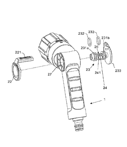
[0013] FIG. 1: an exploded three-dimensional perspective view of the present
invention.
[0014] FIG. 2: an enlarged perspective view of a through channel of a water
dispensing
apparatus of the present invention.
[0015] FIG. 3: an E-E sectional perspective view of FIG. 2.
[0016] FIG. 4: a sectional implementation perspective view of opening an inlet
channel
of the present invention.
[0017] FIG. 5: a sectional implementation perspective view of closing an inlet
channel
of the present invention.
[0018] FIG. 6: an enlarged three-dimensional perspective view of a pivot valve
of the
present invention.
[0019] FIG. 7: an enlarged three-dimensional perspective view from another
angle of a
pivot valve of the present invention.
[0020] FIG. 8: a sectional implementation perspective view of the present
invention.
[0021] FIG. 9: a comparative perspective view for strokes of pivot valve.
DETAILED DESCRIPTION OF THE PREFERRED EMBODIMENT
[0022] In order for well understanding of the present invention, the following
will
provide preferred embodiments and corresponding figures for detail
descriptions.
Corresponding figures of the preferred embodiments of the present invention
will also be
applied for further illustration, so as to help those who skill in the art to
implement the
5
present invention based on the present specification, which however shall not
be used to
limit the scope of the present invention.
[0023] Referring to Figs. 1 to 7 of the drawings, the main body 1 of the water
dispensing apparatus has an inlet channel 11 and an outlet channel 12. The
inlet channel
11 and the outlet channel 12 have a lateral channel 27 therebetween. The
lateral channel
27 has an inlet opening 271 formed by the inlet channel 11 and an outlet
opening 272
formed by the outlet channel 12. The lateral channel 27 is pivotingly
assembled with a
pivot valve 23, wherein the pivot valve 23, which has a column shape, is
longitudinally
extended through the lateral channel 27 of the main body 1 of the water
dispensing
i 0 apparatus. The pivot valve 23 is mounted at the lateral channel 27 in a
pivotally movable
manner, wherein the pivot valve 23 is operatively connect to an actuation
member 221,
wherein the actuation member 221 is arranged to pivotally move the pivot valve
23 so as
to adjust the radial angle of the pivot valve 23 and to therefore controllably
open and
close the inlet opening 271.
[0024] As shown in Figs. 3 and 4, the inlet opening 271 has a prolate shape or
non-
circular shape that a longitudinal width of the inlet opening 271 is larger
than a transverse
width thereof. Preferably, the inlet opening 271 has an oblong oval shape. In
addition,
the longitudinal width of the inlet opening 271 is slightly smaller than a
longitudinal
width of the inlet channel 11. The water flow rate at the inlet opening 271
will be
increased by increasing the longitudinal width of the inlet opening 271, and
the stroke of
the pivot valve 23 will be shortened by reducing the transverse width of the
inlet opening
271.
[0025] The pivot valve 23 has a water sealing portion 24 and a water passing
portion
26 aligned with the water sealing portion 24, wherein the water sealing
portion 24 and the
water passing portion 26 are formed at two opposite sides of the pivot valve
23. In
particular, the pivot valve 23 has two lateral portions to form the water
sealing portion 24
and the water passing portion 26 respectively. The shape of the water sealing
portion 24
of the pivot valve 23 matches with the shape of the inlet opening 271.
Specifically, the
water sealing portion 24 has a sealing surface formed in an elongated curving
6
CA 2922027 2018-06-18
configuration matching with a curvature of a wall of the inlet opening 271,
wherein the
sealing surface of the water sealing portion 24 is preferably formed in an
oblong oval
shape. The longitudinal width of the sealing surface of the water sealing
portion 24 is
larger than a transverse width thereof. Also, the shape of the water sealing
portion 24 is
the elliptic shape that fits to seal at the inlet opening 271. Accordingly,
the water sealing
portion 24 has a sealing area larger than the inlet opening 271, such that the
area of the
water sealing portion 24 is large enough to seal at the inlet opening 271. The
pivot valve
23 further has a groove 241 indently formed on the sealing surface of the
water scaling
portion 24 at a periphery thereof and a sealing element 25 disposed at the
groove 241 at
the sealing surface of the water sealing portion 24.
[0026] When the water sealing portion 24 is misaligned with the inlet opening
271, the
pivot valve 23 is opened to guide water to pass through the outlet channel
272, and when
the water sealing portion 24 is aligned with the inlet opening 271, the pivot
valve 23 is
closed to block the water at the inlet opening 271. In particular, when the
water sealing
portion 24 of the pivot valve 23 is moved to align with the inlet opening 271
at a position
that the sealing surface of the water sealing portion 24 seals at the inlet
opening 271, the
sealing element 25 at the periphery of the sealing surface of the water
sealing portion 24
will tightly seal at a periphery of the inlet opening 271. In other words, the
sealing
element 25 is tightly coupled at the sealing surface of the water sealing
portion 24 to
provide an effective sealing effect for tightly sealing at the inlet opening
271 so as to
prevent any water leakage of the inlet opening 271. The pivot valve 23 further
has two
lateral sides defining a first lateral side 231a and a second lateral side
231b, wherein the
water sealing portion 24 is located between the first and second lateral sides
231a, 231b.
The pivot valve 23 further comprises two sealing rings 232 coupled at the
first and
second lateral sides 231a, 231b respectively for sealing the lateral channel
27, so as to
prevent the water being leaked from the lateral channel 27.
[0027] In addition, the shape of the water sealing portion 24 matches with the
shape of
the inlet opening 271.
7
CA 2922027 2018-06-18
[0028] Furthermore, the pivot valve 23 further comprises a first sheltering
member 233
and a second sheltering member 22, wherein the first sheltering member 233 and
the
second sheltering member 22 form two outer sidewaIls of the pivot valve 23 and
are
coupled at two sides of the main body. The actuation member 221, which serves
as a
manual pusher, is extended between the first sheltering member 233 and the
second
sheltering member 22, wherein the actuation member 221 is manually driven to
move by
the user's finger to pivotally move the pivot valve 23 via the first
sheltering member 233
and the second sheltering member 22, so as to selectively adjust the pivot
angle of the
pivot valve 23. In particular, the actuation member 221 is integrally extended
from the
second sheltering member 22 at a position that a free end of the actuation
member 221 is
coupled at the first sheltering member 233. In other words, the actuation
member 221 is
pushed forward or rearward to control the position of the water sealing
portion 24 of the
pivot valve 23 either to align with the inlet opening 271 or to misalign with
the inlet
opening 271. When the water sealing portion 24 of the pivot valve 23 is
misaligned with
the inlet opening 271, the water passing portion 26 of the pivot valve 23 is
aligned with
the outlet opening 272 for allowing the water to flow out of the outlet
opening 272, i.e.
the working mode of the water dispensing apparatus, as shown in Fig. 5. When
the water
sealing portion 24 of the pivot valve 23 is moved to align with the inlet
opening 271 that
the sealing surface of the water sealing portion 24 seals at the inlet opening
271, the
sealing element 25 at the periphery of the sealing surface of the water
sealing portion 24
will tightly seal at a periphery 273 of the inlet opening 271 for blocking the
water to enter
into the lateral channel 27 from the inlet opening 271, i.e. the closing mode
of the water
dispensing apparatus.
[0029] As shown in Fig. 8, the actuation member 221 is moved at a position C
that the
water sealing portion 24 of the pivot valve 23 is aligned with the inlet
opening 271. The
actuation member 221 is moved at a position D that the water sealing portion
24 of the
pivot valve 23 is misaligned with the inlet opening 271. As Fig. 9 shows, an
actuation
member 221 of prior art brings a pivot valve 23 to pivot, which stroke
required from
closing to opening the water is from position A to position B. However, the
stroke
required from closing to opening the water of the present invention is that
the actuation
8
CA 2922027 2018-06-18
CA 02922027 2016-02-26
member 221 brings the pivot valve 23 to pivot from position C to position D.
Comparing
the stroke of the actuation members 221 of the present invention and the
conventional
water dispensing apparatus, the stroke of the present invention is shorter
than that of the
conventional water dispensing apparatus, such that the present invention
provides an
ergonomic design for the user to push the actuation member 221 by the user's
finger.
[0030] Major features and advantages of the present invention include the
following.
The water sealing portion 24 of the pivot valve 23 fits the inlet opening 271.
Also, the
water sealing portion 24 surroundingly has a groove 241, and the groove 241
accommodates a sealing element 25. Besides, when the sealing element 25 is put
in the
groove 241, the sleeving between the sealing element 25 and the groove 241
still leaves a
minor gap to allow water flow to flush therefrom, so as to allow water flow to
flush back
to push against the sealing element 25 to have it press on the outer periphery
of the inlet
opening 271, which makes the sealing element 25 close the inlet opening 271
more
securely.
[0031] Also, in another embodiment, a side of the water sealing portion 24
surroundingly forms a groove 241. The peripheries of the groove 241 has
multiple gaps
(not shown in the Figs.), wherein the gaps are surroundingly set to the groove
241. The
groove 241 accommodates a sealing element 25. Therefore, when the sealing
element 25
is put into the groove 241, the gaps are able to allow water flow to flush
into the groove
241 therefrom, so as to have the water flow to flush back to push against the
sealing
element 25 to have it press toward the inlet opening 271, which makes the
sealing
element 25 seal the inlet opening 271 more securely.
[0032] Besides, shapes of the inlet opening 271 include rectangle and
rectangle with
rounded corners.
[0033] The preceding description is meant to be illustrative of preferred
embodiments
and should not be construed as limiting the scope of the present invention.
Various
modifications, which would be readily apparent to one skilled in the art, are
intended to
9
CA 02922027 2016-02-26
be within the scope of the present invention. Accordingly, the only
limitations to the
scope of the present invention are set forth in the following claims appended
hereto.