Note: Descriptions are shown in the official language in which they were submitted.
CA 02922173 2016-02-23
WO 2015/027187
PCT/US2014/052350
IN THE UNITED STATES PATENT AND TRADEMARK OFFICE
APPLICATION FOR LETTERS PATENT
SELF-SEALING BALLOONS AND RELATED COMPONENTS AND
METHODS OF MANUFACTURING
CA 02922173 2016-02-23
WO 2015/027187 PCT/US2014/052350
SELF-SEAL1NG BALLOONS AM) RELATED COMPONENTS AND
METHODS OF MANUFACTURING
BA C KG ROUND
EMI] People of an ages enjoy water balloon :fights particularly during hot
weather. Thcse mock battles allow people to:blow off a bit of :steam in a
good.
natured way without harming, anyone, else, indeed, during most water balloon
fights the worst that happens is that someone gets soaked and everyone gets a
good laugh.
100021 One player or side of a water balloon fight often wins based on the
number
of balloons that they can throw during the fight The throw :rate of worse
depends
On Wing able to fill and tie Off the balloons But, both activities ean demand
more
dexterity than many:small children possess. It is also something of a tedious
task
for those not involved in the game (for instance, the parents vksho might be
assiSting their children),
SUMMARY
100031 The following prostas a. iMplified suramtey, it order to provide an
understanding of some aspects of the diselosed subject matter, This summary is
not an extensive overview t:If the disclosed subject matter, and is not
intended to
identify keyieritical &Mang Otto delineate the teopc Of such suNeet matter. A
putpose a the summary is to pmsent some<..!oncepts in a simplified form as a
prelude to the more detailed disclosure that is present:al herein. The current
CA 02922173 2016-02-23
WO 2015/027187 PCT/US2014/052350
disclosure provides balloons, self-sealing water balloons, components thereof
and
related systems, apparatus, methods, etc.
[0004] Some embodiments provide self-sealing water balloons. The balloons of
the current embodiment comprise an elastomerie body, rib, and check valve
ball.
The balloon body defines a body thickness, an unfilled internal volume, and a
filled
internal volume. Furthermore, the balloon body expands between the unfilled
internal
volume and the filled internal volume when filled with fluid. Moreover, when
filled, it
has an internal pressure arising from a tension in the elastometic balloon
body. The
balloon rib is coupled to the balloon body and defines a meniscus region and a
rib
thickness. The rib thickness is greater than the body thickness in the current
embodiment. As to the check valve 'ball, it is buoyant and is located within
the balloon
body. Accordingly, the balloon is configured so that a combination of the
internal
pressure and the buoyancy of the ball urge it toward the rib when the balloon
is partially
filled with water whether oriented vertically.
00051 Various embodiments provide balloons which define elastomeric bodies and
necks. The balloon bodies define body thicknesses and -filled and unfilled
internal
volumes between which the balloons expand and contract when being filled and
emptied
respectively with a first liquid. Tension in the balloon bodies gives rise to
internal
pressures when the balloons are filled. The necks of the current embodiment
couple with
the bodies and define ribs with thicknesses which differ from the body
thicknesses,
10061 In some embodiments the rib thicknesses are greater than the body
thicknesses.
Moreover, the ribs can define concave surfaces when viewed from a.
longitudinal axis of
the balloon passing through the balloon -neck. The balloons of some
embodiments also
comprise cheek valve balls -which are buoyant with respect to the liquid and
which are
located within the balloon body. The internal pressure tends to hold the
check. valve ball
3
CA 02922173 2016-02-23
WO 2015/027187 PCT/US2014/052350
in the rib when the balloon is partially filled with the liquid. Balloons of
some
embodiments define overall thicknesses which vary continuously with distance
along a
longitudinal axis of the balloons and which further defines the body and rib
thicknesses.
100071 Balloon ribs of various embodiments define meniscus regions.
Further, some of
these meniscus regions are defined by differences between the diameters of the
balloon
bodies and necks (the latter diameter often being less than the former
diameter),
Additionally, or in The alternative, some balloons comprise lips which define
lip
diameters and meniscus regions.
iOOOS in accordance with some embodiments, methods of manufacturing
balloons are
provided herein. Some methods, for instance, comprise at least partially
immersing a
mold in a liquid elastomer, The mold, furthermore, comprises a balloon body
portion, a
balloon lip portion, and a balloon neck portion between the body and lip
portions. The
portions each having a cireumferenee, wherein the eircumferences of the neck
portions are
less than the circumferences of at least one of the body and lip portions.
Methods in
accordance with the current embodiment also comprise drawing the mold from the
liquid
elastomer at a (variable) rate sufficient to coat the mold with the liquid
&stoma% As a
result, a thickness of the coating on the neck portion can be different than a
thickness of
the coating on at least one of the body or lip portions. Additionally, such
methods
comprise forming the balloon lip .from the Oast= r on the lip portion. In some
embodiment the mold includes a flat area proximal to, or on, the neck portion.
Moreover,
a (buoyant) check valve bail can be inserted into the balloon and compressed
air can be
used to aid the insertion.
0009.1 Additionally, methods in accordance with the current embodiment can
comprise
molding a first biodegradable material (for instance wood) comprised of fine
particles
into a generally sphetical bell-shapW substrate. Oils in the wood can bind the
particles
4
CA 02922173 2016-02-23
WO 2015/027187 PCT/US2014/052350
together or a binding agent. can be used for such purposes. in the alternative
or in
addition, some methods also comprise coating the spherical substrate with a
second
biodegradable material (and drying the coating). Beeswax can he used for the
coating.
Furthermore, the coated spherical ball can be made in such a way as to possess
a density
which di-11'cm from the density of the water and so that it possesses a total
mass of no
more than about 480 mg. As a result, if the coated spherical ball is
thoroughly wetted
with water and traveling at about 70 feet per second and encounters a human,
it does not
injure the human. Some methods comprise de-burring the generally spherical
substrate to
form the spherical ball and/or dividing a bulk material into the fine
particles. The balls
can be inserted into the balloons in accordance with some embodiments.
100101 Various embodiments provide Check valve balls for use with water
and/or other
liquids. These check valve balls can comprise a ball that further comprises a
generally
spherical substrate of fine particles of a biodegradable material and a
coating on the
substrate. The coating can be made of biodegradable material also. Combined,
the
coating and the generally spherical substrate -form the check valve ball and
possess a
density differing from the water density. Further the check valve ball
possesses a total
mass of no more than about 480 mg. Thus if the coated spherical ball is
thoroughly
wetted with water and traveling at about 70 feet per second and contacts a
human, it does
not injure the human. Check valves of some embodiments can further comprise
balloon
necks which are configured to receive the check valve ball thereby forming
self-sealing
water balloons. A. binder can he included in the check valve hall to bind its
particles
together and/or the check valve ball can be coated with beeswax..
100111 Some embodiments provide molds for self-sealing balloons which
comprise
balloon body, neck, and lip portions each defining a circumference. Moreover,
the neck
portion can be between the lip and body portions and its circumference can he
less than
CA 02922173 2016-02-23
WO 2015/027187 PCT/US2014/052350
either (or both) of the lip and body portions. The neck portion can therefore
define a
fillet. Furthermore, the mold (or perhaps just the neck. portion) can be made
of a material
having a selected wetting property such that, in conjunction with a
characteristic
dimension of the fillet, the mold draws a selected liquid elastoiner into a
region adjacent
to the fillet to form a. meniscus region.
100121 To the accomplishment of the foregoing and related ends, certain
illustrative aspects are described herein in connection with the annexed
figures.
These aspects are indicative of various non-limiting ways in which the
disclosed
subject matter may be practical, all of which are intended to be within the
scope
of the disclosed subject matter. Other novel and nonobvious features will.
become
apparent from the following &Waal disclosure when considered in conjunction
with the figures and are also within the scope of the disclosure.
BRIEF DESCRIPTION OF THE. FIGURES,
100131 The detailed description is described with reference to the
accompanying
figures. in the. figures, the left-most digit(s) of a. reference number
usually
corresponds to the figure in which the reference number first appears < The
use of
the same reference numbers in different figures usually indicates similar or
identical items.
100141 Fig. I illustrates a cross-section of a self-sealing water balloon.
100151 .Fig. 2 illustrates a detail view of the self-sealing water balloon of
Fig. L
100161 Fig. 3 illustrates a mold stem for manufacturing balloons.
100171 Fig. 4 illustrates a graph of the rate at which mold stems are drawn
from a
liquid elastomen
100181 Fig. 5 illustrates a cross-section of a balloon.
6
CA 02922173 2016-02-23
WO 2015/027187 PCT/US2014/052350
100191 Fig. 6 illustrates a cross-section of a self-sealing water balloon.
100201 Fig. 7 illustrates another cross-section of a self-sealing water
balloon.
100211 Fig. 8 illustrates yet another cross-section of a self-sealing water
balloon.
100221 Figs. 9-11 illustrate a method of inserting a check valve ball into
a balloon.
100231 Fig, 12 illustrates a flowchart of a method for manufacturing balloons.
10024j Fig. 13 illustrates a stem mold immersed in a liquid elastomer.
10025] Fig. 14 illustrates a method of manufitctufing check valve balls.
10026] Fig. 15 illustrates a flowchart of a method of manufacturing check
valve
100271 Fig. 16 illustrates a cartridge check valve.
100281 Fig. 17 illustrates another cartridge check valve.
100291 Fig, 18 illustrates another mold stem.
100301 Fig. 19 is a detail view of the mold stem of Fig. 18.
DETA I LED DESCRIPTION
100311 This document discloses balloons, self-sealing water balloons,
components
thereof and related systems, apparatus, methods, etc,
100321 Some embodiments provide water balloons which can be filled and which
maintain water inside without leaking (without the need to be tied off). While
a
ball, sphere, or other type of stopper can he used to seal the balloon (from
within)
other devices can serve as check valves to allow the balloon to be filled
while also
stopping the water (or other fluid) therein from flowing or leaking out of the
balloon, Furthermore, the balloons (and check valves thertvf) can be designed
to
have a limited self-sealing lifetime once filled with water.
7
CA 02922173 2016-02-23
WO 2015/027187 PCT/US2014/052350
100331 Balloons of some embodiments can be said to have distinct parts such as
a
body, a neck, a lip, ribs, seating shoulders, etc. These distinct parts,
though, can be
formed as a singular, unitary object in which the "parts" merely refer to
portions of
the unitary balloons and, indeed, can overlap. However, the various parts of
these
balloons can have differing thicknesses.
I00341 Further still, some embodiments include check valves in the
balloons. For
instance, a ball of compacted wood particles can be coated with beeswax and
inserted into a balloon so that it plugs the neck of the balloon when the
balloon is
full. In some embodiments, the check valve is a gel cap that seals the neck of
the
balloon. Thus, the check valve balls need not be spherical. For instance, they
can
be oblong, ellipsoidal, egg-shaped, etc. In the alternative, or in addition,
the check
valve can include a polyethylene ball and can be used when the users do not
desire
the check valve balls to smudge (however temporarily) surfaces that they might
contact.
100351 Moreover, the cheek valves can include cartridge check valves
inserted into
the balloons. In some embodiments., the cartridge check valve comprises a tube
with a tapered inner wall and a check valve ball retained therein.
Accordingly, a
cartridge check valve can be inserted into the neck of a balloon and the check
valve ball will seal against the tapered wall (with the tube sealing against
the neck
of the balloon). Of course other check valve devices can be used in
conjunction
with balloons to provide auto-sealing balloons. Moreover, these check valve
devices can be made of a variety of materials (either biodegradable and
otherwise). Check valves of embodiments which resist degradation can be re-
used.
8
CA 02922173 2016-02-23
WO 2015/027187 PCT/US2014/052350
100361 chemically-based cheek valves can. be used in accordance with
embodiments. These chemically-based check valves, can include adhesives that
set.
in the presence of water or other fluids) and/or chemicals that are injected
into the
necks of the balloons and that fbrm solidlsemi-solid materials in the presence
of
water. The latter form of Chemically-based check valves could seal the
balloons
after they set. Having generally considered some embodiments it might now be
helpful to turn to the figures.
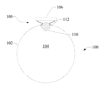
100371 Fig. I illustrates a cross-section of a self-sealing water balloon.
The
balloon 100 includes an elastomeric body 10.2 which defines an internal volume
104, In Fig. 1, the balloon 100 happens to be filled with a liquid so that the
balloon body 102 is expanded and stretched taut. Being taut of course can
facilitate the balloon's impact-induced "explosion." Moreover, the balloon 100
also includes a lip 106 and a neck 108 situated between the lip 106 and the
body
I 0,.
00381 As is further disclosed herein, the neck. 108 can define a -rib. In the
current
embodiment, the tip 106 is a thickened area of the balloon body 102 and allows
users to inject air, water, and other fluids into the balloon 100. 01 course,
that
fluid flows through an aperture defined by the lip 106 and thence through the
neck
1.08 into the internal volume 104. If not sealed, that aperture can allow the
fluid in
the balloon 100 to escape.
100391 The balloon 100 illustrated by Fig. I also includes a check valve
formed
from a check valve ball I 10 and a seating shoulder 112. The cheek valve ball
110
is a spherical ball and has a density different than the fluid in the internal
.volume
104 (or intended to be. in the balloon 100). Of course, in many instances that
fluid
will be water but a large variety of fluids can be in the balloon 100. For
instance,
9
CA 02922173 2016-02-23
WO 2015/027187 PCT/US2014/052350
in some cases the balloon 100 might be used to collect bodily fluids,
industrial
fluids, wastewater, environmental samples, etc. But, for those cases in which
the
fluid is water, the eheck valve ball 110 can be either denser or less dense
than the
water. Of course, the check valve ball 110 could have a density equal to that
of
water Or other fluid) if desired.
00401 With continuing reference to Fig. 1, the seating shoulder 112 can be
formed
at or near the neck 108. And, more specifically, the seating shoulder 112 can
be
formed in the area where the body 102 and neck 108 join. Thus, the check valve
ball 110 can seat against the seating shoulder 112 thereby sealing the balloon
104
and preventing the fluid therein from exiting via the neck 108 and lip 106.
More
specifically still, the taut skin of the body 102 tends to impart an internal
pressure
to the fluid which causes it to flow toward the neck 108 while the balloon is
unsealed. Thus, the check valve ball 110 will tend to flow with the water
until it
encounters the seating shoulder 112. It then comes to rest against the seating
shoulder 112 with the internal pressure pushing it against (and into) the
seating
shoulder 112. At some point the three exerted against the check valve ball 110
by
the seating shoulder 112 (and/or the skin of the body 102) balances the force
imparted thereon by the internal pressure.
100411 The check valve ball 110 can. therefore come to rest seated in the
seating
shoulder 112. It has been found, moreover, that the check valve hall 110 will
stay
seated and continue sealing the balloon 100 despite the orientation and/or
(potentially 6 degree freedom) movement of the balloon 100. Indeed, it has
been
found that. the check valve ball 110 seals the balloon 100 despite the balloon
100
being thrown as in a water balloon fight or otherwise launched (such as by a
gun
designed for use therewith).
CA 02922173 2016-02-23
WO 2015/027187 PCT/US2014/052350
100421 Fig. 2 illustrates a detail view of the self-sealing water balloon
of Fig. L
More specifically, Fig. 2 illustrates various features related to sealing the
balloon
100. For instance, Fig. 2 illustrates the thicknesses t L t2, and t3 of the
body 102
and of the neck 108 in two locations (one at its thickest section and one at.
a
thinner area near the lip 106). The thickest area with thickness t2 is the
seating
Shoulder 112 of the current embodiment. Balloons of the current. embodiment
are
made of latex although balloons 100 of various embodiments can be made from
many other elastomers too numerous to list herein. Of course, balloons of
uniform
thickness can be: used with the check valves disclosed herein to form self-
sealing
balloons.
00431 Table 1, below, shows some typical but non-limiting dimensions, weights,
etc. of balloons of some embodiments.
Ran/Sphere Size (nominal): 10 mm 0.394 in
Mass (nominal): Wood 260 mg
Polyethylene. 480 mg
Balloon Travel Est. Speed Thrown 25 mph 37 fps
Shot 70 mph 1.00 fps
Latex Balloon Wall
Estimated Thickness 0.005 0.008 in or 0127 0.0203 rum
Diameter of
Filled Balloon Thrown 3.00 in
11
CA 02922173 2016-02-23
WO 2015/027187 PCT/US2014/052350
ShOt 150 in
Time to Seal :Filled
Balloon Without
Appreciable Degradation 20 minutes, with 80% efficiency
Table 1: Non4imiting Design Features of Self-Sealing Balloons of 'Embodiments
l00441 Fig. 3 illustrates a mold stem for manufacturing balloons. The mold
stem
300 of the current etnboditnent is dipped into a liquid elastomer (for
instance,
latex) and drawn out of it at. a, rate sufficient to leave a coating of the
liquid
elastomer on the mold stem =300. As the elastomer dries (or sets) it forms =a
balloon 100 corresponding in shape and size to the mold stem 300
100451 The mold stem 300 illustrated by Fig. 3 includes or defines three
general
portions.. These portions include a body portion 302, a lip portion 306, and a
neck
portion 308. The bod.y, lip, and neck portions 302, 3 3=()
308 can be used to
form, respectively; the body WE lip 106, and neek 108 of various balloons 100.
Note also that the mold stem 300 forms one or more fillet portions 312 at or
near
the neck portion 308. Moreover, the mold stem 300 can be 1brinc..'d from wood,
ABS (Acrylonitrile Butadiene Styrene) plastic, or other materials capable of
being
formed with a smooth enough surface to prevent significant defects in the
skins of
the balloons 100.
100461 With continued reference to Fig. 3, the body portion 302 possesses a
generally s.pherical or bulbous shape. That sham in the current embodiment,
imparts a corresponding shape to the balloon body 102. Thus, mold body
portions
12
CA 02922173 2016-02-23
WO 2015/027187 PCT/US2014/052350
302 of various shapes can be used to manufacture balloons 100 having many
different overall shapes. More specifically; the mold stern 300 of the
current.
embodiment has a body portion .302 with a diameter (or circumference) larger
than
that of the lip portion 306 and/or the neck portion 308. Thus, balloons 100
tbrmed
from the mold stem 300 of the current embodiment have larger bodies 102
capable
of holding more water, air, or other fluids. In. some embodiments, the
diameter of
the body is about 3 Inches when filled,
100471 As to the lip portion 306, it is elongated so that sufficient
elastomer adheres
thereon from which to form the lip 106. That lip 106 can be formed by rolling
the
elastomer down the mold stem 300 while it is still semi-dry (or tacky). This
can
be done with a set of rotating brushes which cause the elastomer to curl over
itself
as the brushes (and the curling elastomer) travel along the mold stem 300. As
it is
rolled down the mold stem 300, the tack.y elastomer continues curing and
thereby
forming the lip 106.
100481 Still. with referwee to -Fig. 3, the neck portion 308 of the mold stem
300 of
the current embodiment forms the neck 108 andlor seating Shoulder 112 of
balloons 100. More specifically, the neck portion 308 defines a diameter (or
circumference depending on its shape) that is less than either or both. of the
diameters (or circumference) of the body and/or lip portions 302 and 306.
Thus,
the neck 108 of the balloons 100 formed thereon will tend to be smaller than
the
bodies 102 and lips 106 of the balloons 100.
100491 in some embodiments, the fillet portions 312 assist. in forming the
neck 108
and/or the seating should 11.2 (see Fig. 3), More specifically, and as noted
elsewhere herein, the neck portion 308 can be made of a material which wets
comparatively well when in contact with the liquid elastomer. Thus, it is
believed
13
CA 02922173 2016-02-23
WO 2015/027187 PCT/US2014/052350
that capillary forces tend to draw the liquid elastomer into capillary-like
features
of the mold stern 300 (for instance, the relatively confined regions adjacent
to the
fillet portions 31.2). The fillet portions 312 might therefore tend to retain
more of
the liquid elastomer than other surfaces of the mold stem 300. As a. result,
when
the mold stem 300 is drawn from the liquid elastomer, more elastomer remains
on.
the fillet portions 312 than elsewhere. The resulting balloons 100 will
probably
therefore have a thicker cross-sectional area in the corresponding region.
(the
seating Shoulder 112), In other words, the meniscus that is believed to -form
adjacent to the fillet portion 312 gives rise to the thickness 12 of the
seating
shoulder 112.
100501 That thickness t2 provides more material against which the check valve
ball
110 seats, The extra material reinforces the neck 108 in the vicinity of the
seating
shoulder 112 and prevents (in some embodiments) the check valve ball 110 from
tearing through the balloon 100 in that area. Moreover,, should the seating
shoulder 112 he of insufficient strength to completely resist the force of the
cheek
valve hall 1.10 (acting under the pressure and/or buoyant forces in the
balloon) the
neck 108 will likely collapse upon -the lip 106. The lip 106 (with its extra
material
as compared to the remainder of the body 102) can therefore aid in retaining
the
check valve ball 110 and sealing the balloon 100 of the current embodiment.
While the foregoing has disclosed certain methods of fOrming the
thickened/reinforced seating shoulder 112, other methods of forming them are
within the scope of the current disclosure. For instance, the mold. stem. 300
can be
withdrawn from the liquid -elastomer at a varying rate so as to leave various
portions of the mold stem 300 coated with more/less elastomer than other
areas.
14
CA 02922173 2016-02-23
WO 2015/027187 PCT/US2014/052350
100511 Fig. 4 illustrates a graph of the rate at which mold stems can be drawn
from
a liquid elastomer. More specifically, Fig. 4 shows a graph 400 of the rate
that the
mold stem 300 is withdrawn as a function of the position z at which the liquid
surface is on the mold stem 300. The mph 400 defines several portions such as
body rate 402, lip rate 406, neck rate 408, and fillet rate 412. In accordance
with
the current embodiment, each portion of the graph 400 corresponds to a portion
of
the balloons 100 manufactured with the mold stern 300.
100521 For instance, a particular rate (selected based on the liquid
elastomer to be
used and the material of the mold stem 300) can be used to leave a desired
thickness t3 on the lip portion 306 of the mold stem 300. See lip rate 406.
That
rate can be reduced to slow the rate at which the mold stem 300 is withdrawn
while material is being deposited or coagulated on the fillet portion 312 of
the
mold stern 300. Aceordingly, Fig. 4 illustrates the rate being ramped down
from
the lip rate 406 to the fillet rate 412. A different rate can be selected for
coating
other portions of the neck portion 308 such that the neck raw 408 can be
approximately steady. Then, as the second fillet portion 312 emerges from the
liquid elastomer, the rate can be ramped up to the fillet rate 412 (or,
perhaps, some
other rate). Finally, in accordance with the embodiment illustrated by Fig. 4,
the
mold stem 300 can be withdrawn at a body rate 402 to coat the body portion 302
to some desired thickness. Of course, graph 400 depicts but one rate profile
whereas those skilled in the art will recognize that a rate profile for a
particular
balloon will reflect a number of variables and/or user selections. These
variables
include the wetting ability of the mold stem 300 (or portions thereof), the
properties of the elastomer, the sought after balloon skin thickness or
thicknesses,
the drying/setting time of the liquid elastomer, environmental temperature,
etc.
is
CA 02922173 2016-02-23
WO 2015/027187 PCT/US2014/052350
Another factor that Cat) be considered in manufacturing such balloons is
whether
the amount of liquid elastomer retained on the mold stem 3001s inversely
proportional to the rate or speed of withdrawal.
100531 Accordingly, the rate profile illustrated by Fig. 4 is presented for
illustrative
purposes and is non-limiting. The manner in which the rates can he varied are
also
non-limiting. For instance, a variable frequency drive can be used to vary the
speed of the motor withdrawing the mold stem from the liquid elastomer. In the
alternative, or in addition, the mold stem can ride along a manufacturing rail
which has a height-profile tailored to dip and/or withdraw the mold stem from
the
liquid elastomer at a varied rate.
100541 Fig. 5 illustrates a cross-section of a balloon. The balloon 500 of
Fig. 5 has
been formed with a body 502 reflecting the bulbous shape of the body portion
302
of the mold stem 300 It also reflects the shape of the lip portion 306 and
neck
portion 308. In addition, it possesses a seating shoulder 512. Note that the
balloon 500 can be used as is (without a cheek valve ball) or with a check
valve
ball in accordance with embodiments. Fig. 6 illustrates a cross-section of a
self-
sealing water balloon. In Fig. 6, a check valve ball 610 has been inserted
into the
balloon 600 to form a self-sealing balloon in accordance with embodiments.
Thus,
it can be filled with water (or some other liquid) and used as desired without
being
tied off.
100551 Fig. 7 illustrates another cross-section of a self-sealing water
balloon.
More specifically, Fig. 7 illustrates a balloon 700 with a relatively deflated
and
elongated body 702. This elongated body reflects the shape of the body portion
of
the mold stem on which it was formed. Similarly, its neck 708 possesses an
elongated shape which spans more distance between the body 702 and the lip 706
16
CA 02922173 2016-02-23
WO 2015/027187 PCT/US2014/052350
than the distance between the body 602 and the lip 606 of balloon 600 (see..
Fig.
6). In some embodiments, the length of the neck 708 is about 1 inch. Moreover,
the neck 708 and lip 706 merge along a comparatively straight line rather than
the
are illustrated between neck 608 and the lip 606 (which expands the diameter
of
the neck 608 as it. approaehes the lip 606).
100561 It has been found that the configuration of balloon 600 can improve Ow
ability to fill the balloon 600 (as compared to the balloon 700) using
automated or
semi-automated machinery. More specifically, the shorter-necked balloon 600
can
be held in a magazine (by the relatively short neck 608) and aligned with a
fill
nozzle (not shown) using the magazine. Moreover, the Shorter-necked balloon
600
reduces or eliminates the need for indexing/orienting the balloon 600 before
it is
launched from a water balloon gun designed for use therewith. That short neck
608 also reduces the likelihood of snags between the balloon 600 and the gun
(or
other automated or semi-autotnated handling equipment). Furthermore, it.
reduces
friction and/or stietion between the balloon 600 and the machinery that might
otherwise develop. In contrast, the longer neck 708 of balloon 700 improves
the
ability of users to manually "tie-otr the neck thereby sealing the balloon if
it is
desired to do so and/or no check valve ball 710 is present.
100571 Fig. 8 illustrates yet another cross-section of a self-sealing water
balloon.
More specifically, Fig. 8 shows the balloon 700 as being filled with a liquid
(for
instance water). The check valve hall 710 has been urged into place in the
neck
708 (or rather against the seating shoulder 712) by a combination of buoyant
forces and/or the internal pressure of the balloon 700. As such, it seals the
balloon
700 and prevents the liquid (and/or any gases therein) from leaking from the
balloon 700. As those Skilled in. the art will recognize, the degree to which
the
17
CA 02922173 2016-02-23
WO 2015/027187 PCT/US2014/052350
check valve ball 710 (and seating shoulder 712 seal the balloon can be
determined
by the mechanical and geometric properties of the check valve ball 710 and
seating shoulder 712. Thus, for instance, when the balloon 700 is intended to
hold
water for recreational use, a lesser degree of sealing could be chosen to, for
instance, lower manufacturing costs. However, when the balloon 700 is intended
to hold more sensitive liquids (for instance, bodily fluids, waste, fuel,
etc.) the
balloon 700 can be designed with a greater degree of sealing capability.
Likewise,
the lifetime of the check valve ball can be set by appropriate user choices so
that it
degrades noticeably after some desired time.
100.581 Figs. 9-11 illustrate a method of inserting a check valve ball into
a balloon.
More specifically, Fig. 9 illustrates a pair of jaws 916 holding a check valve
ball
910 which is ready for insertion into the balloon 900. Fig. 9 also illustrates
the
cheek valve ball 910 has a first diameter DI whereas at least a portion 914 of
the
neck 908 has a diameter D2 which is less than the ball diameter DI. The jaws
916, it is noted here, taper together to a point (or at least an end which has
a
diameter smaller than both the ball diameter DI and the neck diameter 1)2.
Thus,
the jaws 916 hold the check valve ball 910 between themselves. While they can
also be inserted through the lip 906 and neck 908, the jaws 916 are
illustrated as
being just outside of the lip 906 and/or the neck 908.
100591 Fig. 10 illustrates the jaws 916 as being partially inserted into
the balloon
900. Fig. 10 also illustrates that the distance that the jaws 916 can be
insetted into
the balloon is enough to position the distal end of the jaws 916 beyond any
point
of the neck 908 having an unstretched neck diameter D2 less than the ball
diameter DI. That distance (and the length of the neck 908) can he chosen in
conjunction with one another so that the portion 914 of the neck 908 to he
engaged
CA 02922173 2016-02-23
WO 2015/027187 PCT/US2014/052350
(and stretched) by the jaws 916 will have sufficient resilience to withstand
that
stretching.
100601 Fig. 11 illustrates the jaws 916 as having been opened. Accordingly,
the
portion 914 of the neck 908 has been stretched to a diameter 1)3 sufficient to
allow
the check valve ball 910 to pass there through. Indeed. Fig. 11 illustrates
the
cheek valve ball 910 as having moved through the neck 908 and into the body
902
of the balloon 900. The jaws 916 can then be closed thereby relaxing the
portion
914 of the neck 908 and trapping the check valve ball 910 in the balloon 900.
100611 While Figs. 9-11 illustrate the check valve ball 910 being gravity-
fed into
the balloon, such arrangements are not necessary. For instance, the balloon
900
and check valve ball 910 could be held in any orientation (for instance,
horizontally, inverted, etc.) with compressed air 920 or some other gas (or a
device) providing the motive force to inject the check valve ball 910 into the
balloon,
j0062 Furthermore, the cheek valve ball 910 could be heavier than the fluid
or
liquid to be sealed in the balloon 900. In that case. the check valve ball 910
would
seal the balloon acting under the internal pressure in the balloon 900. Indeed
while the weight of the check valve ball 910 might partially offset the
pressure-
based force, that pressure could still be enough to hold the check valve ball
910
against the seating shoulder. For instance, an appropriately sized marble was
used
to successfully seal a water balloon even when the balloon was positioned with
the
neck pointing up. Initially, the marble was moved into position against the
seating
shoulder by orienting the filled balloon 900 with its neck pointing down such
that
the marble settled onto the seating shoulder. Once the marble was seated,
though,
it stayed in place despite the balloon being thrownItossedllauriched.
19
CA 02922173 2016-02-23
WO 2015/027187 PCT/US2014/052350
100631 Fig. 12 illustrates a flowchart of a method for manufacturing
balloons.
More specifically, Fig. 12 illustrates the method 1200 which can begin with
forming a mold stem 300 for manufacturing balloons such as balloon 700. The
shape and dimensions of the mold stem 300 can be chosen to produce balloons of
a desired shape and set of dimensions. Moreover, the mold stem 300 can be
formed from a material(s) having wetting properties selected to work in
conjunction with the liquid elastomer it will be immersed in to form the
balloons
700. See reference 1202.
100641 At reference 1204, a body of liquid elastomer can be formed. That
elastomer can be latex, natural rubber, tmvulcanized rubber, polyehloroprene,
etc.
Moreover, various additives such as curing agents, accelerators, oil,
lubricants,
pigments, thickeners, dilutants, coagulants, and/or water can be mixed with
the
latex to yield a set of properties suitable for use with the chosen mold stern
300.
100651 The mold stem 300 can also be treated to improve its properties for use
in
method 1200. For instance, a coagulant can be applied to the mold stern 300
(or
selected portions thereof such as the neck portion 308) to enhance the ability
of the
elastomer to adhere thereto. The mold may then be immersed in the elastomer.
See reference 1206. See Fig. 13 which illustrates the mold stem 300 partially
immersed in a liquid elastomer 1300.
100661 Furthermore, the mold stern 300 can then be withdrawn from the liquid
elastomer 11300 as illustrated at reference 1208. The rate at which it is
withdrawn
may vary. For instance, differing rates may be chosen while the lip portion
306,
the neck portion 308 (and/or the fillet portions 312), and the body portion
302 are
drawn from the liquid elastomer 1300. These rates, moreover, need not be
steady.
For instance they can vary and can be timed (or indexed) to coincide with the
time
CA 02922173 2016-02-23
WO 2015/027187 PCT/US2014/052350
at which the various portions of the mold stem 300 are drawn from the liquid
elastomer 1300, Such rates can be varied, via a variable frequency drive or
set by
means of a manufacturing rail along which the stem molds 300 travel. See
reference 1210.
10067) For instance, a first rate of withdrawal can be used while the lip
portion 306
of the mold stem 300 is being drawn from the liquid elastomer 1300. Sm.
reference 1212. A position sensor can be used in conjunction with the
drive/mechanism withdrawing the mold stem 300 to determine when the neck.
portion 30.8 begins to emerge from the liquid elastomer 1300. See reference
1.214.
100681 Moreover, While the meniscus portions 312 of the mold. stem 300 are at
or
near the surface of the liquid elastomer 1300, the rate can be adjusted to
provide
enough time .for capillary forces to draw enough of the liquid elastomer 1300
to
the fillet portions 312 to form the menisci. Thus, more liquid elasiorner can
coat
the fillet portions 312 than other portions of the mold stern 300. Moreover,
it' the
mold stern 300 defines a flat portion 324 or shelf (to retain additional
material by
means of gravity, viscous forces, surface tension, etc. Or a combination
thereof)
then additional liquid elastomer 1300 can be deposited on the mold stern 300
at
that. location(s). See Fig. 3. Indeed, it is believed (and the mold stem 300
can be
designed such that) surface tension between the flat portion 324 and the
liquid
elastomer 1300 can hold additional liquid elastomer in contact with the flat
portion
324.
100691 Moreover, one or more withdrawal rates can be set for withdrawing the
neck portion 308 of the mold stem 300 from the liquid elastomer 1300. See
reference 1216. The mold stem 300 can. continue being withdrawn in accordance
21
CA 02922173 2016-02-23
WO 2015/027187 PCT/US2014/052350
with that rate(s) as indicated by reference 1218. The neck 708 of the balloon
700
can begin forming as a result. See reference 1220.
100701 As the neck portion 308 emerges from the liquid elastomer 1300 another
withdrawal rate can be set for withdrawing the body portion 302 from the
liquid
elastomer 1300 as references 1222 and 1224. Accordingly, the body portion 302
of the mold stem 300 can be withdrawn from the liquid elastomer 1300 at that
rate
to begin forming the body 702 of the balloon 700. See reference 1226.
100711 At some time, the mold stem 300 becomes completely withdrawn from the
liquid elastomer 1300 in accordance with the current embodiment. The liquid
elastomer 1300 can begin to dry or set (depending on the type of liquid
elastomer
involved) as it (or portions of it emerges from the liquid elastomer. if
desired,
heat, quenching, and/or curing agents can be applied to encourage the
formation of
a solid or senti-solid elastomer on the mold stern 300. Thus, the balloon 700
of the
current embodiment begins to solidify on the mold stem 300.
[00721 Once the liquid elastomer 1300 on the lip portion 306 of the mold stem
300
reaches a sufficiently dry or tacky state, the lip 706 of the balloon 700 can
be
formed. More specifically a set of rotating brushes can be brought into
contact
with the proximal end of the nascent lip 706 while it is still adhering to the
mold
stem 300. These rotating brushes can contact the tacky elastomer and begin
rolling it along the length of the lip portion 306 of the mold stem 300. As
the
brushing continues, the tacky elastomer rolls into a form in which it has a
roughly
spiral-shaped cross section. Moreover, because adjacent layers of tacky
elastomer
in that spiral are brushed into contact with one another, the adjacent layers
are
likely to adhere to one another. As those skilled in the art will recognize,
in such
situations, the tacky elastomer continues to cure thereby forming what appears
to
CA 02922173 2016-02-23
WO 2015/027187 PCT/US2014/052350
be a solid lip 706 but that might have a "spiral" cross-section. When the lip
706 is
formed, the balloon 700 can be removed from the mold stem 300. If desired,
additional balloons 700 can be formed by repeating method 1200 in whole or in
part. See reference 1228,
100731 Fig. 14 illustrates a method of manufacturing cheek valve balls.
More
specifically, Fig. 14 illustrates a shaker table 1400, spray bars 1402,
generally
spherical substrates 1404, spray 1406, and check valve balls 1408. Generally,
to
manufacture check valve balls 1408 from generally spherical substrates 1404,
users can employ the shaker table 1400 and spray bars 1402. More specifically,
the shaker table 1400 is set at an angle Al such that the generally spherical
substrates 1404 can roll down it in accordance with the current embodiment.
After
they are molded, the generally spherical substrates 1404 can be fed on to one
end
of the shaker table 1400. That end of the shaker table 1.402 can define a
roughened surface which is configured to smooth, polish, etc. the generally
spherical substrates 1404 into more spherical substrates 1404 as they roll
along it.
In some embodiments, any molding ribs, risers, etc. that might be present on
the
generally spherical substrates 1404 can be abraded away as the shaker table
1.400
vibrates and as the generally spherical substrates 1404 roll along the subject
portion of the shaker table 1400.
100741 The (now more uniformly) spherical substrates 1404 continue along the
shaker table 1400 until they encounter the spray 1406 created by the spray
bars
1402. The spray can be of any coating suitable for preserving the spherical
substrata. 1404 while the cheek valve balls 1408 might be (subsequently)
immersed in some liquid. For instance, the spray 1406 can be beeswax or some
other biodegradable material. That spray 1406 coats the spherical substrates
1404
23
CA 02922173 2016-02-23
WO 2015/027187 PCT/US2014/052350
as they roll along the shaker table 1400. Indeed, because the shaker table
1400
can be configured to shake the spherical substrates 1400 in such a way that
they
rotate randomly about all three of their axes, the spherical substrates 1404
typically maintain a spherical shape rather than evolving into some other
shape
(for instance cylindrical).
10075j Moreover, as the spherical substrates 1404 move along the shaker table
1400, they become more or less uniformly coated with the spray 11406 in
accordance with the current embodiment, The coated spherical substrates 1404
exit the spray 1406 as they continue along the shaker table 1400. As they do
so
and/or thereafter, the coating dries or sets thereby -limning cheek valve
balls for
use in self-sealing balloons and/or elsewhere. The finished coating can be
smoother than the underlying substrate thereby improving the sealing of the
balloon. Moreover, while the coated cheek valve ball 910 can protect the
underlying substrate from the water (or other liquid in the balloon) for some
time,
it and the underlying substrate can be designed to bio-degrade rather quickly.
For
instance, some beeswax/particulate wooden check valve balls 910 can
essentially
disintegrate (to naturally occurring, non-polluting residues) within a week or
so
during typical summer weather.
100761 Fi& 15 illustrates another method of manufacturing check valve
balls.
More specifically, Fig. 15 illustrates that the method 1500 can include
dividing a
material for a substrate (of a check valve ball) into fine particles. For
instance, a
piece of wood such as pine, oak, ash, etc. can be divided into particles fine
enough
to provide the density, weight, resilience, etc. desired by the user. Of
course other
materials can be used to form the substrate and need not be divided into
particles.
In some embodiments, shredded paper, plastic, glass, etc, can be used to form
the
24
CA 02922173 2016-02-23
WO 2015/027187 PCT/US2014/052350
substrate. However, in accordance with embodiments reference 1502 shows that
particles can be formW from at least some materials. The material of the cheek
valve balls can be biodegradable but need not be so. In some embodiment in
which the check valve balls and the balloons are both biodegradable, the
materials
can be selected so that they both degrade when exposed to typical environments
within some selected time (such as I week). Even polyethylene check valve
balls
can be designed to degrade in the presence of ultraviolet light (in sunlight)
with/without catalysts to enhance the biodegradation so that they degrade
within a
year or less following exposure to the environment. As those skilled in the
art will
understand, with cheek valve balls that biodegrade within a reasonable time,
users
might not need to collect the cheek valve balls of spent water balloons.
100771 Reference 1504 illustrates that a binder can be added to the mass of
particles to be formed into the matrix or substrate of the check valve ball.
Of
course, some materials will allow subsequent processing to be performed
without
adding a binder. For instance, some woods contain enough naturally occurring
oil
that the oil can serve as a binder sufficient to bind the check valve balls
together
for selected uses. Accordingly, the binder used can be selected based on the
desired service environment of the resulting apparatus.
100781 A desired amount of the particulate matter (with or without an added
bindeo can be measured into a mold. That mold can be used to compress the
particulate matter into a generally spherical shape. See reference 1506.
However,
as can occur in many molding processes, certain burrs, "risers," stems, etc.
can be
formed on the substrate as an incidence of their manufacture. Since these
burrs (if
present) might interfere with the seal between the cheek valve ball and the
balloon,
method 1500 includes de-burring the generally spherical substrate manufactured
CA 02922173 2016-02-23
WO 2015/027187 PCT/US2014/052350
during method 1500 in accordance with the current embodiments See reference
1510 The material of these generally spherical substrates can resemble light-
weight (low-density) particleboard or can be some other material.
100791 At reference 1512 a coating can be applied to the now spherical
substrate.
That. coating can be made of a material which is suitable to protect the
substrate
from contact with a :liquid for a selected amount of time. For instance, the
coating
can be configured such that it protects the substrate from water for at least
a few
minutes. in some embodiments, that coating is beeswax and is applied in
sufficient thickness to protect the substrate from water for about 20 minutes
in
about 80% of typical scenarios. In that way, the check valve ball can be
inserted
into a balloon, the balloon can be filled with water, and then used for
leisure
activities (for instance, in a water balloon fight with/without a water
balloon gun)
without being manually tied off.
100801 Some coatings might behave more optimally if they are allowed to dry,
cure, etc. after they are applied to the substrates. Thus, method 1500
includes
drying the coating as illustrated at reference 1514. The, result of method
1500 can
be a spherical check valve ball of approximately 10 mm diameter sufficiently
large.
to seal even many balloons heretofore available While also being light enough
(about 480 mg or less) that even at 70 feet per second it would not hurt a
human
that it might contact. Of course, as might be desired, method 1500 can be
repeated
in whale or in part. See reference 1516.
10081 J Fig. 16 illustrates a cartridge cheek valve of embodiments. More
specifically, Fig. 16 illustrates a cartridge cheek valve 1600 which comprises
a
cylindrical cartridge 1602 and a check valve ball or stopper 1604. The
cartridge
1602 is roughly cylindrical in shape and has inner walls that taper together.
26
CA 02922173 2016-02-23
WO 2015/027187 PCT/US2014/052350
Moreover, the cartridge 1602 also defines a detent 1606 or other retention
mechanism through which the stopper 1604 can be inserted. That detent 1604 can
be configured such that it will retain the stopper 1604 within the cartridge
1602,
The tapered inner walls can also retain the stopper 1604 in the body 1602,
Thus,
the stopper 1604 of the current. embodiment is captured by the cartridge 1602,
E00824 Furthermore, the detent 1606 can be perforated or can define ridges
such
that water and/or other fluids can flow around the stopper 1.604 when it abuts
the
detent. The other end of the body can be open. Thus, water can. flow from the
narrow (and open end) of the cheek valve 1600, around the stopper 1604, and
out
through the other end. in the other direction, though., the Bow of water can
urge
the stopper 1604 against the tapered inner walls thereby sealing the balloon
in
which the cheek valve 1600 has been inserted. in addition to Check valve 1600,
Fig. 16 illustrates an ellipsoidal. stopper 1620 that can be used in
conjunction with
the cartridge-like check valve 1600 or it can be used on its own within a
balloon to
seal the balloon directly
100831 Fig. 17 illustrates another cartridge, check valve. The cartridge
cheek valve
1700 of the current embodiment includes a body or cartridge 1.702 and a
stopper
1704 captured therein. The cartridge 1702 defines a plurality of longitudinal
bypass paths 1708 which (when the cartridge check valve 1700 is in a balloon)
allow fluid to flow into the "balloon to fill it. On the other hand, when the
balloon
is full, the internal pressure urges the stopper 1704 against, the seat 1710
at one end
of the cartridge 1702 (which is itself abutting a seating area of the
balloon). and
Closes off and/or seats the check valve (and balloon) against backflow.
Indeed, in
some embodiments, the cartridge 1702 and stopper '1704 are configured such
that
27
CA 02922173 2016-02-23
WO 2015/027187 PCT/US2014/052350
the bypass paths 1704 are closed off by the stopper 1704 when they are in
those
relative portion.
100841 Fig. 18 illustrates another mold stem. The mold stem 1.800 of the
current
embodiment. includes a body portion 1802, a transition portion 1803, a lip
portion
1806, a neck portion 1808, and an adapter 1810. The body portion is bulbous or
generally spherical in shape and creates correspondingly shaped balloons. The
transition portion 1803 tapers toward, the neck portion 1.808 such that the
balloons
wall also have a tapered and/or arcuate transition from their bodies to their
necks.
Meanwhile, the neck portion 1801 can be formed with three arcs so as to avoid
corners and or intersecting surfaces that might introduce line-Shaped or are-
shaped
defects in the balloons formed thereon. Two of the ares provide localized
transitions from the transition portion 1803 and from the lip portion 1806,
while
the third arc lies there between.
100851 With continuing reference to Fig. 18, the lip portion of the current
embodiment can. serve several functions. For instance, the lips of balloons
can -be
formed on it while it can also extend. far enough finm the neck portion 1808
so
that. one end of the overall mold stem 1300 extends from the liquid elastomer
into
which it is immersed. Thus, the adaptor 1810 can be kept. from contact with
the
liquid elastomer and can be removably attached to a moving manufacturing rail.
The attachment can be by way of a I/4"-20 male thread or other mechanical
couplings. for instance. Such arrangements allow manufacturing rails to
immerse
the mold stem 1800 in troughs of liquid elastomer and to withdraw them
therefrom
in accordance with the height-based profiles of the rails. Fig. 19 is a detail
view of
the mold stem of' Fig. 18. Furthermore, Table 2 lists some non-limiting
manufacturing dimensions of the mold stem 1800.
28
CA 02922173 2016-02-23
WO 2015/027187 PCT/US2014/052350
Size
5.125"
L2 4342"
L3 3.592"
14 0.125"
L5 0.625"
L6 0.783"
17 0.236"
D4 0.750"
D5 0.50(r
D6 0.250"
D7 0.280 to .3125"
RI 0375"
R2 0.063"
R:3 0.063"
R4 0.063"
Al 41 degrees
Table 2: Non-Limiting Mold Stem Dimensions
10086i Embodiments =disclosed herein provide balloons comprising, seating.
shoulders at or near their necks. Various embodiments provide balloons with
features enabling nuichinety to grip and/or index the balloons. 'Urns,
balloons of
some embodiments can he fdkd with fluids of various sorts by machinery in
addition to, or in the alternative to,. being filled manually. Some
embodiments
29
CA 02922173 2016-02-23
WO 2015/027187 PCT/US2014/052350
provide seMsealina -water balloons While some embodiments provide cheek .valve
balls for scaling balloons and/Or other Objects, FUrthermore, embodiments
provide
methods atWor apparatus. (fir instancei manufacturing jaws) for tuanufaeuning
ballOons andlor their 00Mpottent part
CON C US ION
1.00871 Although the stihjett matter has been diselOsed in language
Specific to
struetural :features and/or Methodological tie% it is to be understood that
the
stiblect matter defined in the appended IaiIfl S: not intessatily iirnI ted to
'the,
specific features or acts &Closed above. Radler,, the specific features and at
described herein are diselosed as illustrative implementations of the claims%